1
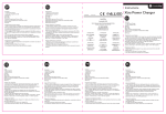
OLYMPIC – FOX – FOX G06
FOX Mod.G02 - G04; OLYMPIC Mod.01 - H07 RN-F 3G1
FOX Mod.G03 - G05; OLYMPIC Mod.02 - PVC 3x1
FOX G06 - H07 RN-F 3G1
ISTRUZIONI
INSTRUCTIONS
ISTRUCCIONES
INSTRUCTIONS
ANWEISUNG
ИНСТРУКЦИИ
FOX G06
FOX
100% MADE IN ITALY
OLYMPIC
FOX Models
G02 - G04
OLYMPIC
Model 01
TECNOPLASTIC S.r.l. Via Calabria, 3-5 CAP 35020 Saonara (PD) – ITALY
Tel: +39/049 8790775 Fax: +39/049 8791140 www.tecnoplastic-srl.it
MANUALE D’ISTRUZIONI - ITALIANO
CARATTERISTICHE
EFFETTUARE I COLLEGAMENTI
TECNICHE
Fox Mod.G02-G04, Olympic 01, FoxG06:
solo modalità svuotamento (Fig.4).
Il cavo di messa a terra è sempre
giallo/verde (Fig.1).
- 20 A carico resistivo
- 8 A carico motore
- Angolo di attivazione: 45°
- Max temperatura: 60° C
- Max profondità: 10m
- Grado di Protezione: IP68
Fox Mod. G03 - G05, Olympic Mod. 02:
Angolo di Attivazione
Svuotamento: (Fig.4) collegando il filo nero
e quello marrone, il circuito apre se il
galleggiante e’ in basso e chiude se il
galleggiante e’ in alto.
Attenzione: isolare il cavo blu (Fig.2).
Riempimento: (Fig.5) collegando il filo nero
e quello blu, il circuito apre se il
galleggiante e’ in alto e chiude se il
galleggiante e’ in basso.
Attenzione: isolare il cavo marrone (Fig.3).
Nota: il circuito a monte deve proteggere
da sovracorrenti entrambi i conduttori.
COME FISSARE IL CONTRAPPESO
a) allentare il dado del contrappeso ed introdurre il cavo del
galleggiante come indicato in figura
b) regolare la posizione del contrappeso in modo da ottenere
l’arco di azione ottimale.
c) fissare il dado e assicurarsi che il contrappeso non scorra
lungo il cavo.
NOTE
• Prima di effettuare qualsiasi operazione sul galleggiante ricordarsi di
•
•
•
•
disconnettere la corrente dal generale;
Controllare che la massima potenza motore non ecceda i valori elettrici del
galleggiante;
Il cavo elettrico è parte integrante del galleggiante stesso. In caso di
danneggiamento del cavo, l’interruttore a galleggiante dev’essere sostituito.
Contrappeso disponibile su richiesta come accessorio;
Non effettuare giunture sul cavo del regolatore di livello: l’immersione può
provocare un corto circuito e scariche elettriche.
INSTRUCTIONS MANUAL - ENGLISH
TECHNICAL FEATURES
INSTALLATION PROCEDURE
- 20 Amps resistive load
- 8 Amps motor load
- Activation angle: 45°
- Max temperature: 60° C
- Max depth:10m
- Protection Grade: IP68
Activation Angle
Fox Mod.G02-G04, Olympic 01, FoxG06:
just emptying function (Fig.4).
The grounding wire is always yellow and
green (Fig.1)
Fox Mod. G03 - G05, Olympic Mod. 02:
Emptying: (Fig.4) when black and brown
wires are used, the circuit opens when float
is down and closes when the float is up. In
this case the blue wire must be insulated
(Fig.2).
Filling: (Fig.5) when black and blue wires
are used, the circuit closes when float is
down and opens when the float is up. In
this case the brown wire must be insulated
(Fig.3).
NOTE: the upstream circuit must protect
the electric wires from the overcurrent.
HOW TO FIX THE COUNTERWEIGHT
a) Loosen the counterweight nut and pass throw the cable as
shown in the picture;
b) Set the counterweight position until you obtain the required
working angle;
c) Fix the nut until the counterweight is blocked.
NOTES
• Before any operation on the float remember to disconnect the power supply
•
•
•
•
from the main power.
Check that the maximum motor power does not exceed the float’s electrical
values.
The electrical cable is part of the floating switch, thus in case of cable
damage, the float itself has to be replaced.
Counterweight is available on request as accessory;
No joints should be made on the level regulator cable, as immersion of
such joints could cause short circuits or electrical shocks.
MANUAL DE INSTRUCCIONES - ESPAÑOL
CARACTERÍSTICAS
CONEXIONES ELÉCTRICAS
TECNICAS
Fox Mod.G02-G04, Olympic 01, FoxG06:
solo vaciamiento (Fig.4).
El cable de la misa a tierra es siempre
amarillo/verde (Fig.1).
- 20 A carga resistiva
- 8 A carga indutiva
- Ángulo de activación: 45°
- Max temperatura: 60° C
- Max profundidad: 10m
- Grado de protección: IP68
Fox Mod. G03 - G05, Olympic Mod. 02:
Ángulo de activación
Vaciar: (Fig.4) conectando el cable negro y el
marrón, el circuito abre si el flotador està
abajo y cierra si està arriba.
Atención: aislar el cable azul (Fig. 2).
Llenar: (Fig.5) conectando el cable negro y el
azul, el circuito abre si el flotador està arriba
y cierra si està abajo.
Atención: aislar el cable marrón (Fig.3).
Nota: el circuito de alimentación tiene que
protejer los dos conductores contra el riesgo
de sobrecorriente.
INSTALACIÓN DE EL CONTRAPESO
a) aflojar el dado del contrapeso y introducir el cable del
flotador como enseñado en la figura a lado.
b) arreglar la posición del contrapeso para obtener el arco de
acción deseado.
c) fijar el dado asegurandose de que el contrapeso no se mueva
a lo largo del cable.
NOTAS
• Recordarse de desconectar la electricidad desde el contador principal antes de
•
•
•
•
efectuar cualquier operación sobre el flotador.
Asegurarse de que el maximo cargo motor no exceda los datos electricos de el
flotador.
El cable electrico es parte integrante del flotador, asì que en caso de que el
cable se dañe hay que reemplazar el flotador mismo.
Contrapeso disponible sobre petición como accesorio.
No efectuar junturas sobre el cable del flotador: la inmersion puede causar
cortocircuitos y descargas eléctricas.
MANUEL D’INSTRUCTIONS – FRANÇAIS
CARACTERISTIQUES
INSTRUCTIONS POUR LE
TECHNIQUES
RACCORDEMENT
- 20 A avec charge resistive a 250v
- 8 A avec charge inductive a 250V
- Angle différentiel: 45°
- Temperature max: 60 °c
- Profondeur max: 10m
- Degré de protection: IP68
Angle différentiel
Fox Mod.G02-G04, Olympic 01, FoxG06:
seulement vidange (Fig.4).
Le conducteur de terre est de couleur
jaune/vert (Fig.1).
Fox Mod. G03 - G05, Olympic Mod. 02:
Vidange: (Fig.4) en utilisant les fils noir et
marron, le contact se ferme si le regulateur
est dirigé vers le haut et il s’ouvre si le
regulateur est dirigé vers le bas. Attention:
isoler le cable bleu (Fig. 2).
Remplissage: (Fig.5) en utilisant les fils noir
et bleu, le circuit se ferme si le regulateur est
dirigé vers le bas, et il s’ouvre si le regulateur
est dirigé vers le haut. Attention: isoler le
cable marron (Fig.3).
Nota: le circuit doit proteger en amont les
deux conducteurs contre les risques de
surintensité.
INSTALLATION DU CONTREPOIDS
a) Dévisser l’écrou du contrepoids et introduire le câble du
regulateur comme indiqué sur le schéma.
b) Régler la position du contrepoids de façon à obtenir
l’amplitude d’action optimale désirée.
c) Ressérer l’écrou du contrepoids en s’assurant que celui ci ne
se deplace plus sur le câble.
NOTES
• Avant d’effectuer n’importe quelle intervention sur le flotteur, s'assurer que
•
•
•
•
l'interrupteur général de ligne est débranché.
Ne pas oublier de vérifier si le courant maximum du moteur correspond aux
valeurs indiquées sur le régulateur de niveau.
Le câble d’alimentation fait partie intégrante du dispositif. Dans le cas où le
câble serait abîmé, le dispositif doit être obligatoirement remplacé.
Le contrepoids serà fournis sur demande comme accessoir.
Eviter le rallongement du câble du regulateur de niveau de façon à ce que son
eventuelle immersion dans l’eau ne provoque ni court-circuit ni surcharge
électrique.
GEBRAUCHSANLEITUNG – DEUTSCH
ANLEITUNGEN FÜR DIE
TECHNISCHE MERKMALE
- 20 A mit 250V ohmscher
Belastung
- 8 A mit 250V induktiver Belastung
- Max. Temperatur: 60°
- Max. Tiefe: 10m
- Schutzgrad: IP68
ANSCHLÜSSE
Fox Mod.G02-G04, Olympic 01, FoxG06:
nur entleerung (Fig.4).
Der gelb/grüne Erdleiter muss an eine
passende Erdklemme geschlossen werden
(Fig.1).
Fox Mod. G03 - G05, Olympic Mod. 02:
Entleerung: (Fig.4) wenn man die Drähte
schwarz und braun benutzt, schließt der
Kreislauf wenn der Schwimmerschalter
oben ist, und er öffnet wenn der
Schwimmerschalter unten ist. Achtung: das
blau Kabel isolieren (Fig. 2).
Füllung: (Fig.5) wenn man die Drähte
schwarz und blau benutzt, schließt der
Kreislauf wenn der Schwimmerschalter
unten ist, und er öffnet wenn der
Schwimmerschalter oben ist.
Achtung: das braun Kabel isolieren (Fig.3).
Anmerkung: der Kreislauf Stromaufwärts
muss beide Leiter vor überstrom schützen.
MONTAGE DES GEGENGEWICHTS
a) Die Mutter am Gegengewicht lockern und das Kabel des
Schwimmerschalters wie auf der Abbildung gezeigt einführen.
b) Die Stellung des Gegengewicht regulieren, so dass der
optimale Aktionsbogen erhalten wird.
c) Die Mutter festziehen und sicher stellen, dass das
Gegengewicht nicht entlang des Kabel gleitet.
NOTES
• Bei den vorgenannten Anschlüssen überprüfen, dass max. Motoren-
Spannung nicht die Werte des Niveaureglers überschreitet.
• Das Speisekabel gehört zu einem festen Bestandteil des Reglers. Sollte
dieses beschädigt sein, muss der Regler ausgewechselt werden.
• Das Gegengewicht wird nur auf anfrage geliefert.
• Verbindungsstellen am Kabel des Standreglers vermeiden, da das
eventuelle eintauchen in Wasser kurzschluss und elektrische Entladungen
verursachen kann.
ИНСТРУКЦИИ - РУССКИЙ
ТЕХНИЧЕСКИЕ
ХАРАКТЕРИСТИКИ
- активная нагрузка 20 A
- нагрузка двигателя 8 A
- Максимальная рабочая
температура. 60° C
- Максимальная глубина 10м
- IP68
ИНСТРУКЦИИ ДЛЯ
ЭЛЕКТРОПРОВОДКИ
Fox Mod.G02-G04, Olympic 01, FoxG06:
опоражнивание (Fig.4).
Проволока для заземления будет всегда
включена в стандартном изделие и
проволочная обмотка будет постоянно
желтого и зеленого или только зеленого
цвета. (Fig.1).
Fox Mod. G03 - G05, Olympic Mod. 02:
Oпоражнивание: (Fig.4)
При
использованиии
Черных
и
коричневых проводов, цепь закроется,
когда поплавок находится вверху, и
откроется, когда поплавок находится
внизу. Предупреждение: Голубой провод
должен быть тщательно изолирован
(Fig.2).
Hаполнение: (Fig.5) При использовании
Черных и Голубых проводов цепь
Акроется когда , поплавок находится
внизу, и откроется когда поплавок
находится вверху. Предупреждение:
Коричневый провод должен быть
Тщательно
изолирован
(Fig.3).
Примечание: Верхняя схема должна
защищать
электропроводку
от
перегрузки по току по току.
УСТАНОВКА ПРОТИВОВЕСА
a) Освободите гайку противовеса и пропустите кабель через
нижнее отверстие, как то показано на рисунке.
b) Установите с помощью противовеса еобходимый для
работы угол.
c) Закрутите гайку, чтобы зафиксировать ротивовес.
внимание
• ПРОТИВОВЕС ПРИ ЗАПРОСЕ;
• Никаких соединенний должно быть сделано в рычаге регуляторе кабеля,
так как осадка подобных соединений может привести к короткому
замыканию или электрическому удару.
CONNESSIONI
CONNECTIONS
CONEXIÓNES
BRANCHEMENT
VERBINDUNG
ПОДСОЕДИНЕНИЮ
Giallo
Verde
Marrone
Blu
Nero
Yellow
Green
Brown
Blue
Black
Amarillo
Verde
Marrón
Azul
Negro
Jaune
Verd
Brun
Bleu
Noir
Gelb
Green
Braun
Blau
Schwarz
желтый
зеленый
Коричневый
синий
Черный
SVUOTAMENTO
VIDER
EMPTYING
ENTLEERUNG
VACIAR
ОПОРАЖНИВАНИЕ
RIEMPIMENTO
FILLING
LLENAR
REMPLIR
FÜLLUNG
НАПОЛНЕНИЕ
TECNOPLASTIC S.r.l. Via Calabria, 3-5 CAP 35020 Saonara (PD) – ITALY
Tel: +39/049 8790775 Fax: +39/049 8791140 www.tecnoplastic-srl.it