1
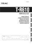
PM-15016-15221-000
Z
LS-W300
OWNER’S MANUAL
ENGLISH
2.1ch Speaker System
MANUEL DU PROPRIÉTAIRE
BEDIENUNGSANLEITUNG
MANUALE DI ISTRUZIONI
FRANÇAIS
MANUAL DEL USUARIO
GEBRUIKSAANWIJZING
ESPAÑOL
Vor der Inbetriebnahme . . . . . . . . . . . .15
Placement of the speakers . . . . . . . . . . . .3
Aufstellung der Lautsprecher . . . . . . . . .15
Connections . . . . . . . . . . . . . . . . . . . . . .4
Anschlüsse . . . . . . . . . . . . . . . . . . . . . .16
Subwoofer . . . . . . . . . . . . . . . . . . . . . . .6
Subwoofer . . . . . . . . . . . . . . . . . . . . . .18
Specifications . . . . . . . . . . . . . . . . . . . . .6
Technische Daten . . . . . . . . . . . . . . . . .18
Sommaire
Indice
Avant Utilisation . . . . . . . . . . . . . . . . . . .7
Istruzioni preliminari . . . . . . . . . . . . . . .19
Disposition des enceintes . . . . . . . . . . . . .7
Posizionamento dei diffusori . . . . . . . . .19
Branchement . . . . . . . . . . . . . . . . . . . . . .8
Collegamenti . . . . . . . . . . . . . . . . . . . . .20
Caisson de grave . . . . . . . . . . . . . . . . . .10
Subwoofer . . . . . . . . . . . . . . . . . . . . . .22
Spécifications . . . . . . . . . . . . . . . . . . . .10
Caratteristiche tecniche . . . . . . . . . . . . .22
Indice
Inhoud
Antes de comenzar . . . . . . . . . . . . . . . .11
Voor gebruik . . . . . . . . . . . . . . . . . . . . .23
Colocación de los altavoces . . . . . . . . . .11
Opstelling van de luidsprekers . . . . . . . .23
Conexión . . . . . . . . . . . . . . . . . . . . . . .12
Aansluitingen . . . . . . . . . . . . . . . . . . . .24
Subwoofer . . . . . . . . . . . . . . . . . . . . . .14
Subwoofer . . . . . . . . . . . . . . . . . . . . . .26
Especificaciones . . . . . . . . . . . . . . . . . . .14
Technische gegevens . . . . . . . . . . . . . . .26
NEDERLANDS
Before Use . . . . . . . . . . . . . . . . . . . . . . .3
ITALIANO
Inhalt
DEUTSCH
Contents
< Do not expose this apparatus to drips or splashes.
< Do not place any objects filled with liquids, such as vases, on
the apparatus.
CAUTION: TO REDUCE THE RISK OF ELECTRIC SHOCK,
DO NOT REMOVE COVER (OR BACK). NO USERSERVICEABLE PARTS INSIDE. REFER SERVICING TO
QUALIFIED SERVICE PERSONNEL.
The lightning flash with arrowhead symbol, within an
equilateral triangle, is intended to alert the user to the
presence of uninsulated “dangerous voltage” within
the product’s enclosure that may be of sufficient
magnitude to constitute a risk of electric shock to
persons.
The exclamation point within an equilateral triangle is
intended to alert the user to the presence of important
operating and maintenance (servicing) instructions in
the literature accompanying the appliance.
IMPORTANT SAFETY INSTRUCTIONS
1)
2)
3)
4)
5)
6)
7)
Read these instructions.
Keep these instructions.
Heed all warnings.
Follow all instructions.
Do not use this apparatus near water.
Clean only with dry cloth.
Do not block any ventilation openings. Install in accordance
with the manufacturer’s instructions.
8) Do not install near any heat sources such as radiators, heat
registers, stoves, or other apparatus (including amplifiers) that
produce heat.
9) Do not defeat the safety purpose of the polarized or
grounding-type plug. A polarized plug has two blades with
one wider than the other. A grounding type plug has two
blades and a third grounding prong. The wide blade or the
third prong are provided for your safety. If the provided plug
does not fit into your outlet, consult an electrician for
replacement of the obsolete outlet.
10) Protect the power cord from being walked on or pinched
particularly at plugs, convenience receptacles, and the point
where they exit from the apparatus.
11) Only use attachments/accessories specified by the
manufacturer.
12) Use only with the cart, stand, tripod,
bracket, or table specified by the
manufacturer, or sold with the
apparatus. When a cart is used, use
caution
when
moving
the
cart/apparatus combination to avoid
injury from tip-over.
13) Unplug this apparatus during lightning storms or when
unused for long periods of time.
14) Refer all servicing to qualified service personnel. Servicing is
required when the apparatus has been damaged in any way,
such as power-supply cord or plug is damaged, liquid has
been spilled or objects have fallen into the apparatus, the
apparatus has been exposed to rain or moisture, does not
operate normally, or has been dropped.
2
< Do not install this apparatus in a confined space such as a
book case or similar unit.
< The apparatus draws nominal non-operating power from the
AC outlet with its STANDBY/ON switch in the standby
position.
< The apparatus should be located close enough to the AC
outlet so that you can easily grasp the power cord plug at any
time.
< An apparatus with Class ! construction shall be connected to
an AC outlet with a protective grounding connection.
< Batteries (battery pack or batteries installed) shall not be
exposed to excessive heat such as sunshine, fire or the like.
< Excessive sound pressure from earphones and headphones
can cause hearing loss.
WARNING: TO PREVENT FIRE OR SHOCK
HAZARD, DO NOT EXPOSE THIS APPLIANCE
TO RAIN OR MOISTURE.
CAUTION
< DO NOT REMOVE THE EXTERNAL CASES OR CABINETS TO
EXPOSE THE ELECTRONICS. NO USER SERVICEABLE PARTS
ARE WITHIN!
< IF YOU ARE EXPERIENCING PROBLEMS WITH THIS PRODUCT,
CONTACT TEAC FOR A SERVICE REFERRAL. DO NOT USE THE
PRODUCT UNTIL IT HAS BEEN REPAIRED.
Before Use
Read this before operation
< Choose the installation location of your unit carefully. Avoid
placing it in direct sunlight or close to a source of heat. Also
avoid locations subject to vibrations and excessive dust, heat,
cold or moisture.
< Do not open the cabinet as this might result in damage to the
circuitry or electrical shock. If a foreign object should get into
the unit, contact your dealer or service company.
Placement of the speakers
You can place the speakers on a shelf, floor, etc. or mount
them on a wall using commercially available screws or
appropriate attachments.
Mounting Bracket
Use the commercially available M5 screws to attach
commercially available brackets to the rear of the speakers.
< When removing the power plug from the wall outlet, always
pull directly on the plug, never yank the cord.
ENGLISH
< Do not attempt to clean the unit with chemical solvents as
this might damage the finish. Use a clean, dry or slightly
damp cloth.
< Keep this manual in a safe place for future reference.
Placement of the subwoofer
The subwoofer should be placed on a hard, flat surface.
Do not cover the front panel and the speaker unit of the
subwoofer.
When placing the subwoofer horizontally, attach feet to the
bottom of the subwoofer with a screwdriver.
Use the supplied black screws.
Disposal of your old appliance
1. When this crossed-out wheeled bin
symbol is attached to a product it means
the product is covered by the European
Directive 2002/96/EC.
2. All electrical and electronic products
should be disposed of separately from
the municipal waste stream via designated collection
facilities appointed by the government or the local
authorities.
3. The correct disposal of your old appliance will help prevent
potential negative consequences for the environment and
human health.
4. For more detailed information about disposal of your old
appliance, please contact your city office, waste disposal
service or the shop where you purchased the product.
3
Connections
Right Speaker
Left Speaker
A
SUBWOOFER OUT
R
L
Amplifier
B
SUBWOOFER
C
CAUTION
< Be sure to read the instruction manual of the amplifier
carefully and switch the power off before connecting the
speaker.
< Connect the provided speaker cables (or other suitable cables)
from the speaker terminals to the terminals of the amplifier.
4
< Be sure that the positive + terminal of the speaker is
connected to the corresponding + terminal of the amplifier,
and that negative _ matches _.
< When connecting to an amplifier having an output higher
than the maximum rated input of the speaker, be careful not
to exceed the speaker’s maximum input, otherwise it will
damage the speaker.
A Speaker Terminals
CAUTION
To avoid damaging the speakers with a sudden high-level
B Subwoofer
Connect to the Subwoofer output jack of the amplifier with
the supplied RCA cable.
signal, turn off the amplifier before connecting the speakers.
The black speaker terminals are _ (negative).
Generally, the + side of the speaker cable is marked to make it
distinguishable from the _ side of the cable. Connect this
marked side to the + terminal and the unmarked side to the
black _ terminal.
Prepare the speaker cables for connection by stripping off
C AC Power Cord
After all other connections have been completed, connect
the plug to the AC wall socket.
Be sure to connect the power cord to an AC outlet which
supplies the correct voltage.
Hold the power plug when plugging or unplugging the
power cord.
approximately 10 mm or less of the outer insulation. (Removing
ENGLISH
too much insulation may lead to a short circuit if the bared
wired should come in contact with each other.) Twist the
strands of the stripped wires tightly together:
CAUTION
The metal portions of the two separate wires should not touch
or an electrical short can occur. Shorted wires can create a fire
hazard or induce a failure in your equipment.
How to Connect
1. Turn the terminal cap counterclockwise to loosen it. The
speaker terminal caps cannot be fully removed from the
base.
2. Insert the wire into the terminal fully and turn the terminal
cap clockwise to securely connect it:
Make sure none of the wire insulation is under the terminal,
only the bare, stripped wire.
3. Make sure it is fastened firmly by pulling the cable lightly.
5
Subwoofer
A
Specifications
L & R Speakers
Unit . . . . . . . . . . . . . . . . . . . . . . . . . . . . . . . 25 mm (tweeter)
80 mm (woofer)
Impedance . . . . . . . . . . . . . . . . . . . . . . . . . . . . . . . . . 4 ohms
Power Handling Capacity . . . . . . . . . . . . . . . . . . . . . . . . 50 W
Sensitivity . . . . . . . . . . . . . . . . . . . . . . . . . . . . . . . . . . . 84 dB
Frequency Response . . . . . . . . . . . . . . . . . . . 120 Hz - 20 kHz
Dimensions (W x H x D) . . . . . . . . . . . . . 120 x 216 x 149 mm
Weight . . . . . . . . . . . . . . . . . . . . . . . . . . . . . . . . . 1.8 kg each
B
C
Subwoofer
Unit. . . . . . . . . . . . . . . . . . . . . . . . . . . . . . . . . . . . . . 200 mm
Output Power . . . . . . . . . . . . . . . . . . . . . . . . . . . . . . . 100 W
Impedance . . . . . . . . . . . . . . . . . . . . . . . . . . . . . . . . . 4 ohms
Sensitivity . . . . . . . . . . . . . . . . . . . . . . . . . . . . . . . . . . . 88 dB
Frequency Response . . . . . . . . . . . . . . . . . . . 45 Hz to 180 Hz
Power requirements . . . . . . . . . . . . . . . . . . . 230 V AC, 50 Hz
Power Consumption . . . . . . . . . . . . . . . . . . . . . . . . . . 100 W
Dimensions (W x H x D) . . . . . . . . . . . . . 270 x 270 x 249 mm
Weight . . . . . . . . . . . . . . . . . . . . . . . . . . . . . . . . . . . . . 8.5 kg
Functions
A VOLUME
Turn this knob to adjust the volume of the subwoofer.
Take care of the total balance between the volume of
subwoofer and front speakers.
B PHASE
Use this switch to select the phase of the subwoofer.
Select either 0 or 180 to achieve the most seamless
integration of energy with front speakers.
C POWER
Use this switch to turn the subwoofer on or off.
This switch lights when the subwoofer is on.
6
Standard Accessories
Speaker Cable (1.8 m) x 2
RCA pin cord
< Design and specifications are subject to change without
notice.
< Illustrations may differ slightly from production models.
Avant Utilisation
Lire ce qui suit avant d’utiliser l’appareil
< Choisissez avec soin l’endroit où vous placerez votre appareil.
Évitez de le placer directement au soleil ou près d’une source
de chaleur. Évitez aussi les endroits sujets à des vibrations, à
de la poussière excessive, à la chaleur, au froid ou à
l’humidité.
< N’ouvrez pas le coffret car ceci risquerait de provoquer des
dommages aux circuits ou des chocs électriques. Si un objet
étranger pénétrait dans l’appareil, contactez votre revendeur
ou un centre de service.
Disposition des enceintes
Vous pouvez placer les enceintes sur une étagère, sur le sol,
etc. ou les monter sur un mur en utilisant des vis en vente
dans le commerce ou les supports appropriés.
Support de montage
Utilisez des vis M5 en vente dans le commerce pour attacher
des supports en vente dans le commerce à l’arrière des
enceintes.
< Lors du débranchement du cordon d’alimentation de la prise
murale, tirez toujours sur la fiche et non pas sur le cordon.
< N’essayez pas de nettoyer l’appareil avec des solvants
chimiques car ceci pourrait endommager le fini de l’appareil.
Utilisez un chiffon propre et sec ou légèrement humide.
< Gardez soigneusement ce manuel d’instructions pour une
référence future.
FRANÇAIS
Disposition du caisson de grave
Le caisson de grave doit être placé sur une surface dure et
plate.
Ne recouvrez pas le panneau avant et le haut-parleur du
caisson de grave.
Quand vous pouvez le caisson de grave horizontalement, fixez
les pieds au-dessous du caisson de grave avec un tournevis.
Utilisez les vis noires fournies.
Mise au rebut de votre ancien appareil
1. Quand ce symbole de poubelle sur roues
barrée d’une croix est joint à un produit,
cela signifie que ce produit est couvert
par la Directive Européenne 2002/96/EC.
2. Tous les produits électriques et
électroniques doivent être jetés
séparément des ordures ménagères via des collecteurs
désignés agréés par le gouvernement ou les autorités
locales.
3. La gestion correcte de l’élimination de votre ancien appareil
aide à prévenir les conséquences potentiellement négatives
pour l’environnement et la santé humaine.
4. Pour des informations plus détaillées sur la mise au rebut
de votre ancien appareil, veuillez contacter votre mairie, le
service de traitement des ordures ou le magasin dans lequel
vous avez acheté le produit.
7
Branchement
Enceinte droite
Enceinte gauche
A
SUBWOOFER OUT
R
L
Amplificateur
B
SUBWOOFER
C
ATTENTION
< Avant de connecter l’enceinte acoustique, veiller à lire
attentivement le mode d’emploi de l’amplificateur et à mettre
ce dernier hors tension.
< Connecter les câbles d’enceinte fournis (ou d’autres câbles
adéquats) des bornes de l’enceinte aux bornes de
l’amplificateur.
8
< Veiller à ce que la borne positive + de l’enceinte soit
connectée à la borne + correspondante de l’amplificateur, et
à ce que la borne négative _ soit bien connectée au _.
< Lors de la connexion à un amplificateur dont la puissance de
sortie est supérieure à la puissance nominale maximale
d’entrée de l’enceinte, veiller à ne pas dépasser cette
dernière; sinon l’enceinte sera endommagée.
A Bornes Enceintes
ATTENTION
Pour éviter d’endommager les enceintes avec un brusque signal
de haut niveau, mettez l’amplificateur hors tension avant de
raccorder les enceintes.
B Caisson de grave
Raccordez le caisson de grave à la prise de sortie de caisson
de grave de l’amplificateur à l’aide du câble Cinch fourni.
C Cordon Secteur
Les bornes noires des enceintes correspondent au _ (bornes
négatives).
Généralement, le côté + des câbles d’enceinte est indiqué ou
identifié par une couleur, qui le distingue du _. Raccordez le
côté ainsi marqué à la borne + et le côté dépourvu de marque
à la borne _.
Avant de raccorder les câbles des enceintes, préparez-les en les
dénudant sur environ 10 mm maximum, de la gaine isolante
(pas plus pour éviter tout risque de court-circuit). Torsadez les
brins des extrémités de fils dénudés:
Après avoir terminé toutes les autres connexions, branchez
le câble dans une prise secteur.
Assurez-vous de raccorder le câble à une prise qui délivre
une tension correcte.
Tenez la prise lorsque vous branchez ou débranchez le câble
secteur.
FRANÇAIS
ATTENTION
Les parties métalliques de deux fils séparés ne doivent jamais se
toucher pour éviter tout risque de court-circuit. Les fils en
court-circuit peuvent provoquer un incendie ou détériorer
sérieusement votre appareil.
Commet effectuez les raccordements
1. Desserrez le capuchon de protection en tournant dans le
sens inverse des aiguilles d’une montre. Ces capuchons de
protection ne peuvent pas être retirés complètement de la
base.
2. Insérez à fond le fil dans la borne et tournez le capuchon de
protection dans le sens des aiguilles d’une montre pour que
le raccorder solidement:
Veillez à ce que seule la partie dénudée du fil soit sous la
borne et non la gaine isolante.
3. Tirez légèrement sur le câble pour vérifier qu'il est bien fixé.
9
Caisson de grave
A
Spécifications
Enceintes G & D
Haut-parleur . . . . . . . . . . . . . . . . 25 mm (haut-parler d’aigus)
80 mm (haut-parleur de graves)
Impédance . . . . . . . . . . . . . . . . . . . . . . . . . . . . . . . . . 4 ohms
Capacité de puissance soutenue . . . . . . . . . . . . . . . . . . 50 W
Sensibilité . . . . . . . . . . . . . . . . . . . . . . . . . . . . . . . . . . . 84 dB
Fréquence . . . . . . . . . . . . . . . . . . . . . . . . . . 120 Hz - 20 kHz
Dimensions (L x H x P) . . . . . . . . . . . . . . 120 x 216 x 149 mm
Poids . . . . . . . . . . . . . . . . . . . . . . . . . . . . . . . . 1,8 kg chacun
B
C
Caisson de grave
Haut-parleur . . . . . . . . . . . . . . . . . . . . . . . . . . . . . . . 200 mm
Puissance de sortie . . . . . . . . . . . . . . . . . . . . . . . . . . . . 100 W
Impédance . . . . . . . . . . . . . . . . . . . . . . . . . . . . . . . . . 4 ohms
Sensibilité . . . . . . . . . . . . . . . . . . . . . . . . . . . . . . . . . . . 88 dB
Réponse en fréquence . . . . . . . . . . . . . . . . . . 45 Hz à 180 Hz
Alimentation . . . . . . . . . . . . . . . . . . . . . Secteur 230 V, 50 Hz
Consommation . . . . . . . . . . . . . . . . . . . . . . . . . . . . . . 100 W
Dimensions (L x H x P) . . . . . . . . . . . . . . 270 x 270 x 249 mm
Poids . . . . . . . . . . . . . . . . . . . . . . . . . . . . . . . . . . . . . . 8,5 kg
Fonctions
A VOLUME
Tournez ce bouton pour régler le volume du caisson de grave.
Faites attention à l’équilibre entre le volume du caisson de
grave et des enceintes avant.
B PHASE
Utilisez cet interrupteur pour choisir la phase du caisson de
grave.
Sélectionnez 0 ou 180 afin d’obtenir la meilleure intégration
possible d’énergie avec les enceintes avant.
C POWER
Utilisez sur cet interrupteur pour mettre le caisson de grave
sous ou hors tension.
L’interrupteur est allumé quand le caisson de grave est sous
tension.
10
Accessoires Standard
Câble d’enceinte (1,8 m) x 2
Cordon Cinch (RCA)
< La conception et les spécifications peuvent être modifiées
sans avis préalable.
< Les illustrations peuvent différer légèrement des modèles de
production.
Antes de comenzar
Léase antes de continuar
< Elija cuidadosamente el emplazamiento de la unidad. No
coloque la unidad a la luz solar directa ni cerca de fuentes de
calor. Evite también los lugares expuestos a vibraciones o a un
exceso de suciedad, frío, calor o humedad.
< No abra la carcasa de la unidad, ya que podrían dañarse los
circuitos o producirse descargas eléctricas. Si entra algún
cuerpo extraño en la unidad, póngase en contacto con su
distribuidor o empresa de servicios.
Colocación de los altavoces
Puede situar los altavoces en un estante, en el suelo, etc., o
fijarlos a una pared con unos tornillos que puede adquirir en
un comercio o con unos dispositivos de fijación adecuados.
Soporte de montaje
Utilice tornillos M5 disponibles comercialmente para fijar
ménsulas disponibles comercialmente a la parte trasera de los
altavoces.
< Cuando desconecte el cable de la toma mural, sostenga
únicamente el conector y nunca el propio cable.
< No intente limpiar la unidad con disolventes químicos, ya que
podrían dañar el acabado. Utilice un paño limpio y seco.
< Conserve el manual en un lugar seguro para futuras
consultas.
Colocación del subwoofer
ESPAÑOL
El subwoofer deberá colocarse sobre una superficie dura y
plana.
No cubra el panel frontal ni la unidad de altavoz del
subwoofer.
Si coloca el subwoofer horizontalmente, fije los soportes de
pie a la base con un destornillador.
Utilice los tornillos negros suministrados.
Reciclaje de su producto viejo
1. Cuando se adjunta a un producto este
símbolo tachado de un contenedor con
ruedas, significa que el producto está
cubierto por la Directiva Europea
2002/96/EC.
2. Todos los productos eléctricos y
electrónicos se deben reciclar de un modo separado del
sistema municipal de basura, a través de las instalaciones
de recogida señaladas por el gobierno o las autoridades
locales
3. El reciclaje correcto de su producto viejo ayudará a prevenir
las consecuencias negativas potenciales para el ambiente y
la salud humana.
4. Para una información más detallada sobre el reciclaje de su
producto viejo, contacte por favor con su ayuntamiento,
servicio de basuras o la tienda en donde usted compró el
producto.
11
Conexión
Altavoz derecho
Altavoz izquierdo
A
SUBWOOFER OUT
R
L
Amplificador
B
SUBWOOFER
C
PRECAUCIÓN
< Asegúrese de leer cuidadosamente el manual de instrucciones
del amplificador y desactivar la energía antes de conectar la
bocina.
< Conecte los cables de las bocinas que se suministran (u otros
cables adecuados) de las terminales de las bocinas a las
terminales del amplificador.
12
< Asegúrese que la terminal positiva + de la bocina esté
conectada a la terminal correspondiente del amplificador y
que la terminal negativa _ sea correspondida de igual
manera.
< Cuando conecte un amplificador que tenga una salida más
alta que la entrada de capacidad máxima de la bocina, tenga
cuidado de no exceder la entrada máxima de la bocina, de lo
contrario se dañará la bocina.
A Terminales de altavoz
PRECAUCIÓN
Para evitar daños a los altavoces con una señal repentina de
alto nivel, apague el amplificador antes de conectar los
altavoces.
B Subwoofer
Conecte la toma de salida del subwoofer del amplificador
con el cable RCA suministrado.
C Cable de alimentación (c.a.)
Los terminales de altavoz negros son el negativo _.
Por lo general, la parte positiva + del cable de altavoz está
identificada (franja, color...) para distinguirla de la parte
negativa. Conecte el extremo positivo al terminal +, y el
negativo al terminal negro.
Prepare los cables de altavoz para la conexión, pelando
como máximo 10 mm de aislante (no más, para evitar
cortocircuitos). Trence los hilos con firmeza:
Una vez realizadas todas las conexiones restantes, conecte el
cable de alimentación a la toma mural.
Asegúrese de conectar el cable de alimentación a una toma
de red que suministre la tensión adecuada.
Sostenga siempre el cable de alimentación por el conector.
PRECAUCIÓN
Las porciones metálicas de los dos cables no deberán
tocarse, ya que se podría producir un cortocircuito. Los hilos
cortocircuitados pueden ocasionar riesgo de incendio o
fallos en el equipo.
ESPAÑOL
Conexiones
1. Gire el casquillo del terminal hacia la izquierda para aflojarlo.
Los casquillos de los terminales de altavoz no se pueden
desprender por completo de la base.
2. Inserte el hilo a fondo en el terminal y gire el casquillo hacia
la derecha para dejarlo debidamente conectado:
Compruebe que no queda nada de aislante debajo del
terminal, únicamente el hilo desnudo.
3. Compruebe que queda bien conectado tirando ligeramente
del cable.
13
Subwoofer
A
Especificaciones
Altavoces frontales y envolventes
Unidad . . . . . . . . . . . . . . . . . . . . . . . . . . . . . 25 mm (tweeter)
80 mm (woofer)
Impedancia . . . . . . . . . . . . . . . . . . . . . . . . . . . . . . . 4 ohmios
Capacidad de manejo de potencia . . . . . . . . . . . . . . . . . 50 W
Sensibilidad . . . . . . . . . . . . . . . . . . . . . . . . . . . . . . . . . . 84 dB
Respuesta en frecuencia . . . . . . . . . . . . . . . . 120 Hz - 20 kHz
Dimensiones (anch. x alt. x prof.) . . . . . . 120 x 216 x 149 mm
Peso . . . . . . . . . . . . . . . . . . . . . . . . . . . . . 1,8 kg cada unidad
B
C
Subwoofer
Unidad . . . . . . . . . . . . . . . . . . . . . . . . . . . . . . . . . . . 200 mm
Potencia de salida . . . . . . . . . . . . . . . . . . . . . . . . . . . . 100 W
Impedancia . . . . . . . . . . . . . . . . . . . . . . . . . . . . . . . 4 ohmios
Sensibilidad . . . . . . . . . . . . . . . . . . . . . . . . . . . . . . . . . . 88 dB
Respuesta en frecuencia . . . . . . . . . . . . . . . . . 45 Hz a 180 Hz
Alimentación . . . . . . . . . . . . . . . . . . . . . . . . 230 V c.a., 50 Hz
Consumo de energía . . . . . . . . . . . . . . . . . . . . . . . . . . 100 W
Dimensiones (anch. x alt. x prof.) . . . . . . 270 x 270 x 249 mm
Peso . . . . . . . . . . . . . . . . . . . . . . . . . . . . . . . . . . . . . . . 8,5 kg
Funciones
A VOLUME
Ajuste el volumen del subwoofer con este mando.
Tenga en cuenta el balance total de volumen entre el
subwoofer y los altavoces frontales.
Accesorios estándar
Cable de altavoz (1,8 m) x 2
Cable con conector RCA
• El diseño y las especificaciones están sujetos a cambios sin
previo aviso.
• Las ilustraciones pueden diferir de los modelos de producción.
B PHASE
Seleccione la fase del subwoofer con este interruptor.
Seleccione 0 o 180 para lograr la mejor coordinación posible
con los altavoces frontales.
C POWER
Apague o encienda el subwoofer con este interruptor.
El interruptor se iluminará si el subwoofer está encendido.
14
Vor der Inbetriebnahme
Lesen Sie diese Hinweise vor der Inbetriebnahme.
< Wählen Sie den Aufstellungsort Ihres Geräts vorsichtig. Halten
Sie das Gerät von Orten mit direkter Sonneneinstrahlung oder
von einer Hitzequelle fern. Vermeiden Sie auch Orte, die
Erschütterungen ausgesetzt sind und an denen übermäßig
viel Staub vorhanden ist, sowie besonders heiße, kalte oder
feuchte Orte.
< Öffnen Sie nicht das Gehäuse, da die Schaltungen dadurch
beschädigt werden könnten bzw. die Gefahr eines
elektrischen Schlages besteht. Falls Fremdkörper in das Gerät
gelangen, wenden Sie sich an Ihren Fachhändler bzw. eine
Kundendienstfirma.
Aufstellung der Lautsprecher
Sie können die Lautsprecher auf einem Regal, auf dem
Boden usw. aufstellen bzw. sie an der Wand mit im
Fachhandel erhältlichen Schrauben und Befestigungsstücke.
Befestigungsbügel
Verwenden Sie handelsübliche M5-Schrauben, um die im
Fachhandel erhältlichen Befestigungsbügel auf der Rückseite
der Lautsprecher zu befestigen.
< Fassen Sie zum Abziehen des Netzkabels immer den Stecker
an, und ziehen Sie nie am Kabel selbst.
< Reinigen Sie das Gerät nie mit chemischen Reinigungsmitteln,
da anderenfalls das Gehäusefinish beschädigt werden kann.
Verwenden Sie zum Reinigen ein sauberes, trockenes oder
leicht angefeuchtetes Tuch.
< Bewahren Sie diese Bedienungsanleitung an einem sicheren
Ort auf, um später darin nachschlagen zu können.
Aufstellung des Subwoofers
Der Subwoofer sollte auf einer harten, ebenen Fläche
aufgestellt werden.
Bedecken Sie nicht die Frontplatte und die Lautsprechereinheit
des Subwoofers.
Entsorgung ihrer alten elektrischen oder elektronischen
Geräte
DEUTSCH
1. Sofern ein Gerät mit dem Symbol einer
durchkreuzten Abfalltonne
gekennzeichnet ist, bedeutet dies, dass
dessen Entsorgung gemäß der
„RICHTLINIE 2002/96/EG DES
EUROPÄISCHEN PARLAMENTS UND DES
RATES vom 27. Januar2003 über Elektround Elektronik-Altgeräte“ geregelt ist.
Wenn Sie den Subwoofer waagerecht hinlegen, befestigen Sie
die Füße mit einem Schraubenzieher auf der Unterseite des
Subwoofers.
Verwenden Sie die mitgelieferten schwarzen Schrauben.
2. Sämtliche elektrischen und elektronischen Geräte müssen
dementsprechend, getrennt vom Restmüll, den von der
jeweils zuständigen städtischen oder Bundesbehörde dazu
bestimmten, gesonderten Wertstoffsammlungen zugeführt
werden.
3. Eine korrekte Entsorgung ihrer alten elektrischen oder
elektronischen Geräte trägt in hohem Maße der
Vermeidung möglicher negativer Konsequenzen für die
Umwelt und damit auch für ihre eigene sowie die
Gesundheit Anderer bei.
4. Weiterführende Informationen bezüglich der Entsorgung
ihrer alten elektrischen oder elektronischen Geräte erhalten
Sie auf Anfrage bei ihrem zuständigen Stadtbüro,
Abfallentsorgungsgesellschaft oder dem Händler, bei dem
Sie das Gerät ursprünglich erworben haben.
15
Anschlüsse
Rechter Lautsprecher
Linker Lautsprecher
A
SUBWOOFER OUT
R
L
Verstärker
B
SUBWOOFER
C
VORSICHT
< Bitte lesen Sie die Bedienungsanleitung des Verstärkers
aufmerksam durch, und schalten Sie die Stromversorgung
aus, bevor Sie den Lautsprecher anschließen.
< Schließen Sie die mitgelieferten Lautsprecherkabel (oder
andere geeignete Kabel) von den Lautsprecherklemmen an
die Klemmen des Verstärkers an.
< Achten Sie darauf, die positiven Klemme + des Lautsprechers
mit der entsprechenden positiven Klemme + des Verstärkers
zu verbinden, und die negative Klemme _ des Lautsprechers
mit der negativen Klemme _ des Verstärkers.
16
< Beim Anschluss an einen Verstärker, der einen höhere
Ausgangsleistung
aufweist
als
die
maximale
Nennausgangsleistung des Lautsprechers, achten Sie bitte
darauf, dass die maximale Nennausgangsleistung des
Lautsprechers nicht überschritten wird, da der Lautsprecher
anderenfalls beschädigt wird.
A Lautsprecheranschlüsse
ACHTUNG
Um eine Beschädigung der Lautsprecher infolge eines
Signals mit unerwartet hohem Pegel zu vermeiden, schalten
Sie den Verstärker aus, bevor Sie die Lautsprecher
anschließen.
Die
schwarzen
Lautsprecheranschlussklemmen
repräsentieren den Minuspol _.
Üblicherweise sind Lautsprecherboxen-Anschlusskabel
gekennzeichnet. Der (farbig) markierte Leiter entspricht
hierbei dem Pluspol. Verbinden Sie daher den (farbig)
markierten Leiter mit dem + -Anschluss und den
unmarkierten Leiter mit dem _-Anschluss.
Isolieren Sie maximal 10 mm der Boxenkabel ab. Längere,
unisolierte Enden können sehr leicht zu Kurzschlüssen
führen. Verdrillen Sie die abisolierten Enden der Kabel so
fest, dass keine einzelnen Drähte herausragen können:
B Subwoofer
Für den Anschluss an die Subwoofer-Ausgangsbuchse des
Verstärkers mit dem mitgelieferten Cinch-Kabel.
C Netzkabel
Nachdem Sie sämtliche Kabelverbindungen zwischen den
Komponenten Ihres Systems hergestellt haben, verbinden
Sie das Netzkabel mit einer Wandsteckdose.
Vergewissern Sie sich bitte, dass die Wandsteckdose, an der
Sie das Audiosystem anschließen möchten, die korrekte
Netzversorgung zur Verfügung stellt.
Ziehen Sie bitte nicht am Netzkabel. Verbinden oder ziehen
Sie stets den Stecker des Netzkabels.
ACHTUNG
Achten Sie bitte darauf, dass sich die beiden abisolierten
Enden der Kabel nicht berühren, da dies andernfalls zu
Kurzschlüssen führen kann, die möglicherweise einen Kabeloder Gerätebrand sowie irreparable Schäden an Ihrem HiFiSystem bedingen könnten.
DEUTSCH
Anschließen der Lautsprecherboxen
1. Drehen Sie die Klemmschrauben der Anschlussklemmen
gegen den Uhrzeigersinn, um die Kabel anschließen zu
können. Die Klemmschrauben lassen sich nicht komplett aus
ihren Gewinden herausschrauben.
2. Stecken Sie die abisolierten Kabelenden in die
Anschlussöffnungen, und ziehen Sie die Klemmschrauben
fest an (im Uhrzeigersinn drehen):
Achten Sie darauf, dass Sie nicht anstelle der abisolierten
Kabelenden die Kabelummantelung festgeklemmt haben.
3. Vergewissern Sie sich durch leichtes, vorsichtiges Ziehen,
dass die Kabel richtig festgeklemmt sind.
17
Subwoofer
Technische Daten
Lautsprecher L & R
Einheit . . . . . . . . . . . . . . . . . . . . . . . . . . 25 mm (Hochtöner)
80 mm (Tieftöner)
Impedanz . . . . . . . . . . . . . . . . . . . . . . . . . . . . . . . . . . 4 ohm
Leistungsaufnahme . . . . . . . . . . . . . . . . . . . . . . . . . . . . 50 W
Empfindlichkeit . . . . . . . . . . . . . . . . . . . . . . . . . . . . . . . 84 dB
Frequenzgang . . . . . . . . . . . . . . . . . . . . . . 120 Hz bis 20 kHz
Abmessungen (B x H x T) . . . . . . . . . . . . 120 x 216 x 149 mm
Gewicht . . . . . . . . . . . . . . . . . . . . . . . . . . . . . . . . . . je 1,8 kg
A
B
Subwoofer
Einheit . . . . . . . . . . . . . . . . . . . . . . . . . . . . . . . . . . . 200 mm
Ausgangsleistung. . . . . . . . . . . . . . . . . . . . . . . . . . . . . 100 W
Impedanz . . . . . . . . . . . . . . . . . . . . . . . . . . . . . . . . . . 4 ohm
Empfindlichkeit . . . . . . . . . . . . . . . . . . . . . . . . . . . . . . . 88 dB
Frequenzgang . . . . . . . . . . . . . . . . . . . . . . . 45 Hz bis 180 Hz
Leistungsanforderungen . . . . . . . . . . . . . . . . 230 V GS, 50 Hz
Leistungsaufnahme . . . . . . . . . . . . . . . . . . . . . . . . . . . 100 W
Abmessungen (B x H x T) . . . . . . . . . . . . 270 x 270 x 249 mm
Gewicht . . . . . . . . . . . . . . . . . . . . . . . . . . . . . . . . . . . . 8,5 kg
C
Funktionen
A Laustärkeregler (VOLUME)
Verwenden Sie diesen Regler, um die Lautstärke des
Subwoofers einzustellen.
Achten Sie auf die Gesamtausgewogenheit zwischen der
Lautstärke des Subwoofers und der der Frontlautsprecher.
B Phasenschalter (PHASE)
Verwenden Sie diesen Schalter, um die Phase des Subwoofers
zu wählen.
Wählen Sie entweder 0 oder 180, um die beste Integration
mit der Tonenergie der Frontlautsprecher zu erzielen.
C Netzschalter (POWER)
Verwenden Sie diesen Schalter, um den Subwoofer ein- oder
auszuschalten.
Dieser Schalter leuchtet, wenn der Subwoofer eingeschaltet
ist.
18
Standardzubehör
Lautsprecherkabel (1,8 m) x 2
Cinchkabel
< Änderungen des Designs und der technischen Daten ohne
vorherige Ankündigung vorbehalten.
< Die Abbildungen können leicht von den tatsächlichen
Modellen abweichen.
Istruzioni preliminari
Prima di mettere in funzione l’apparecchio, si prega di
leggere attentamente queste istruzioni.
< Scegliere con cura il luogo dove installare l’apparecchio,
evitando che sia esposto alla luce solare diretta o troppo
vicino ad una sorgente di calore. Evitare anche luoghi soggetti
a vibrazioni, sbalzi di temperatura o condizioni eccessive di
polvere od umidità.
< Non togliere il coperchio, per non correre il rischio di
danneggiare i circuiti interni o provocare fenomeni di
folgorazione. Se un oggetto estraneo dovesse penetrare
nell’apparecchio, rivolgersi al rivenditore o al Servizio
assistenza.
Posizionamento dei diffusori
I diffusori si possono collocare su uno scaffale, oppure
montare su appositi supporti (come il TEAC modello STD2000); si possono anche appendere ad una parete fissandoli
con viti normalmente disponibili, o con staffe adeguate.
Fissaggio delle staffe
Per fissare al lato posteriore dei diffusori una staffa di
supporto del tipo reperibile in commercio si possono usare
comuni viti M5.
< Dovendo staccare il cavo d’alimentazione dalla presa di rete,
non tirarlo direttamente, ma afferrarlo per la spina.
< Per la pulizia dell’apparecchio non usare solventi chimici, che
potrebbero danneggiare la finitura esterna. Basta passare un
panno morbido, asciutto.
< Conservare questo manuale in un luogo sicuro, dove sia facile
consultarlo in caso di necessità.
Posizionamento del subwoofer
Il subwoofer va collocato sul pavimento, facendo attenzione a
non coprire il pannello frontale e l’altoparlante.
Quando viene posizionato in senso orizzontale, montare i
piedini d’appoggio sul pannello inferiore, fissandoli con le 4
viti nere in dotazione.
Smaltimento di apparecchi usati
ITALIANO
1. Quando questo simbolo con il bidone
della spazzatura attraversato da una
croce viene apposto su un prodotto
significa che questo è conforme alle
direttive Europe 2002/96/EC.
2. Tutti i prodotti elettrici ed elettronici
devono essere smaltiti separatamente dagli altri tramite
canali specifici indicati dalle autorità Comunali locali.
3. Per ottenere le necessarie informazioni relative allo
smaltimento dei Vostri apparecchi elettrici usati Vi invitiamo
a contattare gli uffici Comunali a ciò preposti od il
Rivenditore ove avete appena acquistato questo prodotto.
19
Collegamenti
Diffusore destro
Diffusore sinistro
A
SUBWOOFER OUT
R
L
Amplificatore
B
SUBWOOFER
C
ATTENZIONE
< Prima di collegare questi altoparlanti Vi consigliamo di leggere
attentamente le istruzioni dell’amplificatore e comunque di
accertar Vi che sia spento.
< Collegare con i cavetti in dotazione (o con altri comunque
adatti) i terminali dell’amplificatore a quelli posti sul retro
degli altoparlanti.
20
< Attenzione a collegare il terminale positivo + di ciascun
altoparlante al terminale positivo + dell’amplificatore e lo
stesso per i terminali negativi _.
< Se dovrete collegare questi altoparlanti ad un amplificatore di
potenza maggiore rispetto a quella massima ammessa per gli
altoparlanti, fate attenzione a non alzare troppo il volume:
potreste danneggiarli e questo sarebbe un danno non coperto
dalla garanzia.
A Terminali dei diffusori
Attenzione
Per evitare di danneggiare i diffusori con segnali improvvisi
d’intensità molto elevata si raccomanda di spegnere
l’amplificatore prima di collegarli.
B Subwoofer
Alla presa di uscita subwoofer dell’amplificatore si deve
collegare il cavo RCA fornito in dotazione.
C Cavo d’alimentazione
I terminali neri, contrassegnati _, hanno polarità negativa.
Di solito, l’estremità positiva del cavo di un diffusore è
appositamente contrassegnata, o di colore diverso, per
poterla distinguere dall’estremità negativa. Inserire perciò
l’estremità contrassegnata nel terminale + e quella senza
contrassegno nel terminale nero _.
Preparare i cavi di collegamento dei diffusori spellando le
loro estremità per una lunghezza massima di 10 mm (non di
più, per non provocare un cortocircuito) e attorcigliarle poi
strettamente in modo che non si abbiano a formare parte di
cavo “libere”:
Dopo aver eseguito tutti i collegamenti necessari, inserire la
spina del cavo d’alimentazione in una presa di corrente.
Accertarsi che il cavo d’alimentazione venga inserito in una
presa che eroghi la corretta tensione.
Per inserire od estrarre il cavo d’alimentazione afferrarlo
sempre per la spina.
ATTENZIONE
Le parti metalliche dei due fili non devono toccarsi, per non
provocare un cortocircuito, con relativo danneggiamento
degli stadi finali di amplificazione.
Per effettuare il collegamento
1. Ruotare in senso antiorario il cappellotto del connettore per
allentarlo.
2. Inserire a fondo il filo nel connettore e ruotare in senso
orario il cappellotto per rendere ben saldo il collegamento
ITALIANO
Accertarsi che nel connettore entri soltanto la parte
metallica del filo, senza nessun residuo del rivestimento in
plastica.
3. Per accertarsi che il collegamento sia stato ben effettuato,
provare a tirare leggermente il filo.
21
Subwoofer
Caratteristiche tecniche
Diffusori destro e sinistro
Altoparlanti . . . . . . . . . . . . . . . . . . . . . . . . . 25 mm (tweeter)
80 mm (woofer)
Impedenza . . . . . . . . . . . . . . . . . . . . . . . . . . . . . . . . . 4 ohm
Potenza max.accettata . . . . . . . . . . . . . . . . . . . . . . . . . . 50 W
Efficienza . . . . . . . . . . . . . . . . . . . . . . . . . . . . . . . . . . . 84 dB
Risposta in frequenza . . . . . . . . . . . . . . . . . . 120 Hz - 20 kHz
Dimensioni (A x L x P) . . . . . . . . . . . . . . . 120 x 216 x 149 mm
Peso . . . . . . . . . . . . . . . . . . . . . . . . . . . . . . . . 1,8 kg ciascuno
A
B
C
Subwoofer
Altoparlante . . . . . . . . . . . . . . . . . . . . . . . . . . . . . . . 200 mm
Potenza d’uscita. . . . . . . . . . . . . . . . . . . . . . . . . . . . . . 100 W
Impedenza . . . . . . . . . . . . . . . . . . . . . . . . . . . . . . . . . . 4 ohm
Efficienza . . . . . . . . . . . . . . . . . . . . . . . . . . . . . . . . . . . 88 dB
Risposta in frequenza . . . . . . . . . . . . . . . . . . . 45 Hz - 180 Hz
Alimentazione . . . . . . . . . . . . . . . . . . . . . . 230 V c.a., 50 Hz
Consumo elettrico . . . . . . . . . . . . . . . . . . . . . . . . . . . . 100 W
Dimensioni (L x A x P) . . . . . . . . . . . . . . . 270 x 270 x 249 mm
Peso . . . . . . . . . . . . . . . . . . . . . . . . . . . . . . . . . . . . . . . 8,5 kg
Funzioni
A VOLUME
Ruotare questa manopola per regolare il volume del
subwoofer.
Cercare di ottenere il bilanciamento totale tra il volume del
subwoofer e quello dei diffusori anteriori.
B PHASE
Questo interruttore permette di selezionare la fase del
subwoofer.
Selezionare 0 oppure 180 per ottenere la minore interferenza
con i diffusori anteriori.
C POWER
Premere questo interruttore per accendere e spegnere il
subwoofer.
L’interruttore s’illumina quanto il subwoofer è acceso.
22
Accessori in dotazione:
Cavo dell’altoparlante (1,8 m) x 2
Cavo con pin RCA
• L’aspetto e le caratteristiche sono soggetti a modifiche senza
preavviso.
• Le illustrazioni possono lievemente differire dai modelli di
produzione.
Voor gebruik
Lees dit voor u het toestel gaat gebruiken
< Kies de plek waar u uw toestel opstelt met zorg uit. Zet het
toestel niet in de volle zon, of in de buurt van een
warmtebron. Vermijd ook plekken die blootstaan aan
trillingen en teveel stof, warmte, kou of vocht.
Opstelling van de luidsprekers
U kunt de luidsprekers op een plank zetten, of op de vloer
enz. of u kunt ze aan de wand bevestigen met behulp van in
de handel verkrijgbare schroeven of andere geschikte
bevestigingsmaterialen.
Bevestigingsbeugel
< Maak de behuizing niet open, want dit kan leiden tot schade
aan de interne schakelingen of tot elektrische schokken.
Mocht er een vreemd voorwerp in het toestel terecht
gekomen zijn, neem dan contact op met uw dealer of
reparateur.
Gebruik in de handel verkrijgbare M5 schroeven om eveneens
los verkrijgbare beugels aan de achterkant van de luidsprekers
te bevestigen.
< Wanneer u de stekker uit het stopcontact haalt, moet u altijd
aan de stekker zelf trekken, nooit aan het snoer.
< Probeer in geen geval het toestel schoon te maken met
chemische oplosmiddelen, want deze kunnen de afwerking
aantasten. Gebruik een schone, droge of enigszins vochtige
doek.
< Bewaar deze handleiding op een veilige plek zodat u er later
nog eens iets in kunt opzoeken.
Opstelling van de subwoofer
De subwoofer moet op een harde en vlakke ondergrond
worden geplaatst.
Dek het voorpaneel en het luidsprekerdeel van de subwoofer
niet af.
Verwijdering van uw oude elektrische of elektronische
apparaten
1. Als op een apparaat een symbool staat
met een kruis door een afvalton dan
betekent dit dat de verwijdering ervan
volgens de „RICHTLIJN 2002/96/EG VAN
HET EUROPESCHE PARLEMENT EN DE
RAAD van 27 januari 2003 met
betrekking tot elektrische en
elektronische apparaten“ geregeld is.
Wanneer de subwoofer horizontaal geplaatst wordt, dient u
de voetjes aan de onderkant van de subwoofer te bevestigen
met behulp van een schroevendraaier. Gebruik hiervoor de
meegeleverde zwarte schroeven.
2. Al dit soort elektrische en elektronische apparaten moeten
dientengevolge, gescheiden van ander restafval, op een
door de staatsoverheid of de betreffende locale autoriteiten
te bepalen inzamelplaats ingeleverd worden.
NEDERLANDS
3. Een correcte verwijdering/afvoer van uw oude elektrische of
elektronische apparaten draagt in hoge mate bij tot het
voorkomen van een negatieve invloed op het milieu en
levert daarmee ook een positieve bijdrage aan uw eigen
gezondheid en die van anderen.
4. Verdere informatie over de afvoer van uw oude elektrische
of elektronische apparaten kunt u op aanvraag verkrijgen
bij
het
betreffende
gemeentehuis,
de
afvalverwerkingorganisatie of bij de handelaar/winkel waar
u het apparaat oorspronkelijk gekocht heeft.
23
Aansluitingen
Rechter luidspreker
Linker luidspreker
A
SUBWOOFER OUT
R
L
Versterker
B
SUBWOOFER
C
WAARSCHUWING
< Lees de handleiding van de versterker zorgvuldig door en
schakel de stroom uit voor u de luidsprekers aansluit.
< Gebruik de meegeleverde luidsprekerkabels (of andere
geschikte kabels) om de luidsprekeraansluitingen te verbinden
met de aansluitingen op de versterker.
< Let op dat de positieve + aansluiting van de luidspreker
wordt verbonden met de corresponderende positieve +
aansluiting van de versterker, en dat hetzelfde geldt voor de
negatieve _ aansluiting van de luidspreker en de _
aansluiting van de versterker.
24
< Bij aansluiting op een versterker met een hoger
uitgangsvermogen dan het maximale opgegeven vermogen
van de luidspreker, moet u oppassen dat het maximale
ingangsvermogen van de luidspreker niet overschreden
wordt, want hierdoor zou de luidspreker beschadigd kunnen
raken.
A Luidsprekeraansluitingen
WAARSCHUWING
Om te voorkomen dat de luidsprekers beschadigd raken
door een plotseling luid signaal, moet u de versterker
uitschakelen voor u de luidsprekers aansluit.
De zwarte luidsprekeraansluitingen van de versterker zijn de
negatieve _ aansluitingen.
Bij de meeste luidsprekerkabels is de + draad van de
luidsprekerkabel gemerkt of gekleurd om onderscheid
mogelijk te maken met de _ draad van de kabel. Verbind
de gemerkte/gekleurde draad met de + aansluiting en de
ongemerkte kant met de zwarte _ aansluiting.
Bereid de luidsprekerkabels voor aansluiting door ca. 10 mm
of iets minder van de isolatie te verwijderen (niet meer
omdat dit kortsluiting kan veroorzaken). Draai de uiteinden
van de kabels stevig in elkaar om loshangende draden en
een mogelijk daaruit voortkomende kortsluiting te
voorkomen:
B Subwoofer
Sluit deze aan op de uitgangsaansluiting voor de subwoofer
van de versterker door middel van de meegeleverde RCA
(tulpstekker) kabel.
C AC Netsnoer
Als alle andere aansluitingen gemaakt zijn sluit dan pas de
netstroomkabel aan op de wandcontactdoos.
Let er op dat het netsnoer op een stopcontact met de juiste
spanning, die overeenkomt met de spanning van het
apparaat, wordt aangesloten.
Gebruik altijd de stekker om het netsnoer in het stopcontact
te doen of om het netsnoer uit het stopcontact te halen.
WAARSCHUWING
Let er op dat de metalen einden van de twee draden niet
met elkaar in aanraking komen omdat dit kortsluiting tot
gevolg kan hebben. Dit kan mogelijk brand veroorzaken
en/of uw HiFi systeem ernstig beschadigen.
Aansluiten van de luidsprekers
1. Draai het aansluitdopje tegen de wijzers van de klok in los.
Het aansluitdopje kan niet van de basis verwijderd worden.
2. Steek de draad volledig in de aansluiting en draai het dopje
met de wijzers van de klok mee stevig vast.
NEDERLANDS
Let er op dat geen isolatiemateriaal van de draad in de
aansluiting komt, steek alleen het metalen gedeelte van de
kabel in de aansluiting.
3. Controleer of de luidsprekerkabels stevig vast zitten door er
licht aan te trekken.
25
Subwoofer
Technische gegevens
L & R luidsprekers
Luidsprekereenheid . . . . . . . . . . . . . . . . . . . 25 mm (tweeter)
80 mm (woofer)
Impedantie . . . . . . . . . . . . . . . . . . . . . . . . . . . . . . . . . 4 Ohm
Vermogen . . . . . . . . . . . . . . . . . . . . . . . . . . . . . . . . . . . 50 W
Gevoeligheid . . . . . . . . . . . . . . . . . . . . . . . . . . . . . . . . . 84 dB
Frequentierespons . . . . . . . . . . . . . . . . . . . . 120 Hz - 20 kHz
Afmetingen (b x h x d) . . . . . . . . . . . . . . 120 x 216 x 149 mm
Gewicht . . . . . . . . . . . . . . . . . . . . . . . . . . . . . 1,8 kg per stuk
A
B
C
Subwoofer
Luidsprekereenheid . . . . . . . . . . . . . . . . . . . . . . . . . . 200 mm
Uitgangsvermogen. . . . . . . . . . . . . . . . . . . . . . . . . . . . 100 W
Impedantie . . . . . . . . . . . . . . . . . . . . . . . . . . . . . . . . . 4 Ohm
Gevoeligheid . . . . . . . . . . . . . . . . . . . . . . . . . . . . . . . . . 88 dB
Frequentierespons . . . . . . . . . . . . . . . . . . . . . . 45 Hz - 180 Hz
Stroomvoorziening . . . . . . . . . . . . 230 V wisselstroom, 50 Hz
Stroomverbruik . . . . . . . . . . . . . . . . . . . . . . . . . . . . . . 100 W
Afmetingen (b x h x d) . . . . . . . . . . . . . . 270 x 270 x 249 mm
Gewicht . . . . . . . . . . . . . . . . . . . . . . . . . . . . . . . . . . . . 8,5 kg
Functies
A VOLUME
Verdraai deze knop om het volume van de subwoofer in te
stellen. Let hierbij op de algehele balans tussen het volume
van de subwoofer en dat van de voor-luidsprekers.
B PHASE
Met deze schakelaar kunt u de fase van de subwoofer
instellen.
Kies tussen 0 en 180 om de beste resultaten te verkrijgen in
combinatie met de voor-luidsprekers.
C POWER
Hiermee kunt u de subwoofer aan of uit zetten. Deze
schakelaar licht op wanneer de subwoofer aan staat.
26
Standaard toebehoren
Luidsprekerkabel (1,8 m) x 2
RCA (tulp) stekkersnoer
< Ontwerp en technische gegevens kunnen zonder
kennisgeving gewijzigd worden.
< De afbeeldingen kunnen iets afwijken van de
productiemodellen.
Z
TEAC CORPORATION
1-47 Ochiai, Tama-shi, Tokyo 206-8530, Japan Phone: (042) 356-9156
TEAC AMERICA, INC.
7733 Telegraph Road, Montebello, California 90640 Phone: (323) 726-0303
TEAC CANADA LTD.
5939 Wallace Street, Mississauga, Ontario L4Z 1Z8, Canada Phone: (905) 890-8008
TEAC MEXICO, S.A. De C.V
Campesinos N°184, Colonia Granjas Esmeralda, Delegacion Iztapalapa, CP 09810, México DF Phone: (525) 581-5500
TEAC UK LIMITED
Unit 19 & 20, The Courtyards, Hatters Lane, Watford, Hertfordshire, WD18 8TE, U.K. Phone: (0845) 130-2511
TEAC EUROPE GmbH
Bahnstrasse 12, 65205 Wiesbaden-Erbenheim, Germany Phone: 0611-71580
TEAC AUSTRALIA PTY., LTD.
A.B.N. 11 113 998 048
30 Tullamarine Park Road, Tullamarine, VIC 3043, Australia Phone: (03) 8336-6500
This appliance has a serial number located on the rear panel. Please record
the model number and serial number and retain them for your records.
Model number
Serial number
1107. MA-1295A