1
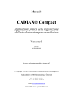
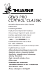
Slidematic Facebow Instruction Manual Slidematic Gesichtsbogen Gebrauchsanleitung Le mesureur facial Slidematic Manuel d’utilisation Arco Facciale Slidematic Manuale D’Istruzione Arco Facial Slidematic Manual de Instrucciones Table of Contents I. Rationale for Development . .............................................. 2 II. Benefits and Features . ....................................................... 2 III. Slidematic Facebow Procedure ......................................... 4 IV. Mounting Procedure .......................................................... 6 V. Slidematic Accessories ...................................................... 8 VI. Reordering . ........................................................................ 8 VII.Warranty ............................................................................. 8 1 I. Rationale for Development Based on in-depth analysis of the facebows on the market engineers in conjunction with several leading clinicians and educators prepared a list of criteria for the development of this new facebow. The Slidematic Facebow was designed to satisfy the following requirements: • An accurate earbow that moves straight horizontally for different facial widths, unlike the caliper type that moves off the vertical axis. • A minimal number of parts and finger screws to permit a facebow registration to be taken in less time. • The ability to send the bitefork assembly (without the measuring bow) to the laboratory, preventing damage to the bow in transit. • Ease of mounting the maxillary cast by not having to transfer the measuring bow to the articulator. • The capability of taking multiple facebow records at the lowest possible cost through the use of only one measuring bow and different bitefork assembly for each case. II. Benefits and Features Facebow Transfer The facebow transfer procedure establishes the relationship of the maxillary dentition to the horizontal reference plane so that the maxillary cast may be mounted on the articulator in the correct anatomical position. The Slidematic Facebow provides a fast, easy and extremely accurate means of transferring the proper anatomical relationship to the articulator. Benefits and Features • The precision manufacturing of the unique “speed-slide” gear mechanism makes it very easy to assemble the bow on the patient. • The right and left arms of the measuring bow are geared to precise equidistant movement from the center of the bow. • The scale on the measuring bow represents the patient’s intercondylar distance (not the interbow distance) 2 for ease in setting articulators having this adjustment. • The Slidematic Facebow can be used on all DENAR® articulators. It also adapts for use with SAM®, Whip Mix®, and HANAU™ articulators. • The bow uses the external auditory meatus reference point for determining the arbitrary hinge axis location. • The built-in reference pointer aligns the bow with the horizontal reference plane. • The built-in sight can be used to view the anterior reference point. • The measuring bow should not be mounted on the articulator during the transfer procedure. The bow, when detached from the vertical shaft, can be used again immediately with the additional transfer jigs (vertical shaft, bitefork assembly and articulator index). In this manner, the maxillary casts may be mounted at any time. • In one step the bitefork assembly is secured to the articulator index and maxillary cast can be mounted to the articulator. • All finger screws are easily accessible from the front. • The procedures can be readily delegated to auxiliary personnel. 1 1 2 2 6 3 3 4 4 5 Transfer Jig Assembly Measuring Bow 1. earplug 2. anterior reference pointer 3. intercondylar distance scale 4. "finger" “finger” lockscrew 5. center Center"lock" “lock”wheel wheel 6. sight Sight 1. dentulous bitefork 2. bitefork index notch 2 3. vertical shaft 3 4. articulator index 4 reference reference plane plane locator locator reference plane marker For a further breakdown, refer to DENAR® Slidematic Facebow Parts List #8815-1. Sterilize bitefork before each use. 3 III. Slidematic Facebow Procedure Mark the anterior reference point on the patient’s right side using the Reference Plane Locator and Marker. The point is 43 millimeters above the incisal edge of the right central or lateral incisors (see Figure 1). On an endentulous patient, measure up from the lower border of the upper lip when it is in repose. Cover the metal with two thicknesses of baseplate wax softened in warm water (approximately 135˚F or 55˚ C). With the bitefork arm to the patient’s right, place the fork in the mouth, aligning the patient’s midline with the index notch, so that it is parallel with the patient’s coronal and horizontal planes (see Figure 2). Be certain to obtain a light indexing of the patient’s maxillary arch and then ask the patient to hold the bitefork in place. Attach the vertical shaft to the measuring bow with the clamp marked #2 on the patient’s right and tighten the finger screw (see Figure 3). It is necessary to tighten this finger screw to secure the vertical shaft to the measuring bow and also to avoid movement. This same movement will occur after inserting the vertical shaft in the articulator index as shown in Figure 12. Be sure to tighten the finger screw. Loosen the finger screws on the clamps marked #1 and #2 on the vertical shaft. With your thumb, loosen the center wheel on the top of the measuring bow and slide the bow open to accommodate the width of the patient’s face. Assemble the facebow on the patient by sliding the bitefork arm through the hole in clamp #2 as the measuring bow’s earpieces are placed in the patient’s auditory meatus (see Figure 4). Tighten the center wheel on the measuring bow and loosen the finger screw on the anterior reference pointer. Raise or lower the bow so that the pointer or sight aligns precisely with the anterior refer- Figure 1 Figure 2 Figure 3 Figure 4 Figure 5 4 ence point (see figure 5) and tighten clamp #1, then clamp #2 (see Figures 6 and 7). When tightening clamps #1 and #2, care must be taken not to displace the bow to either side by having the vertical shaft rest on the fingers as shown in Figure 6. The patient’s inter-condylar distance is the measurement indicated on the scale (see Figure 8). Record this measurement. Loosen the finger screw on the measuring bow, slide the bow open, and remove the entire facebow from the patient. Detach the measuring bow from the transfer jig by loosening the finger screw (see Figure 9). Having completed the procedures involving the patient, the bitefork assembly (see Figure 10) may be labeled with the patient’s name and set aside while the measuring bow portion can be used with an additional bitefork assembly for the next patient. Figure 6 Figure 7 Note: The metal bitefork, vertical shaft and earpieces can be sterilized in an autoclave EXCEPT for the black finger screws on the #1 and #2 clamps. Remove the finger screws (and spacers) before autoclaving or use cold sterilization. Sterilize bitefork before each use. Figure 8 Figure 9 Figure 10 5 IV. Mounting Procedure A benefit of using the DENAR® Slidematic Facebow is that multiple transfer jigs may be used with only one measuring bow. In some cases the mounting of the maxillary cast can be delegated to the laboratory, involving no loss of accuracy and no period of time without facebow transfer capability in the dental office. The laboratory can attach an articulator index to its own DENAR® articulator and mount the maxillary cast using only the bitefork assembly from the dental office. Each articulator index positions the bitefork assembly on any DENAR® articulator so that the relationship with the condyles recorded on the patient is accurately reproduced on the articulator. Figure 11 Mounting The Maxillary Cast Replace the incisal table on the articulator with the articulator index (see Figure 11). With the numbers on clamps #1 and #2 in the upright position, secure the vertical shaft of the bitefork assembly in the hole of the articulator index. Tighten the finger screw on the front edge of the index (see Figure 12). Attach a mounting plate to the upper bow. Be sure that the incisal pin is at the zero position and that the upper bow is level and parallel to the table top. The position that the incisal pin sits on the articulator index is determined by the type of incisal pin being used. When using standard incisal pins, the incisal pin should set on top of the movable slide insert on the articulator index (see Figure 13). When using the incisal pin with the long centric adjustment, it sits on the highest section of the movable slide insert. In situations where the Slidematic Facebow is being used with the same articulator, secure the movable insert with a drop of wax once the insert’s appropriate location has been determined. 6 Figure 12 Figure 13 Place the maxillary cast in the wax index on the bitefork, close the articulator, and mount the cast with stone to the mounting plate (see Figure 14). Normally, a maxillary cast support is not necessary, although one may be used, if desired. Once the stone has hardened, remove the transfer jig and replace the incisal table in the articulator. Mounting The Mandibular Cast Attach a mounting plate to the lower bow. A centric relation checkbite record is used to mount the mandibular cast. With the maxillary cast attached to the articulator and the centric latch engaged, invert the articulator and place the centric relation checkbite record between the maxillary and mandibular casts (see Figure 15). Stabilize the position of the casts with either a rubber band or sticky wax. Adjust the incisal pin to accommodate the increased vertical distance caused by the thickness of the centric relation bite record. Double check to be certain that the condyles are seated against the rear and tops of the fossae, and using stone, proceed to mount the madibular cast to the mounting plate on the articulator (see Figure 16). Figure 14 Figure 15 Figure 16 7 V. Slidematic Accessories The Slidematic uses either a dentulous or edentulous bitefork. The Slidematic Facebow can be used with other articulators and indexes are available for the HANAU™, Whip Mix®, and SAM® models. Standard Biteforks Indexes VI. Reordering Standard Biteforks Part No. 200029 200030 Dentulous Edentulous Articulator Indexes Part No. 200080 200082 200086 200088 DENAR® HANAU™ SAM® Whip Mix® Other Part No. 200009-1 200007 101217 Transfer Jig Assembly Bitefork/Shaft Assembly Maxillary Cast Support Denar® and Whip Mix® are registered trademarks and Hanau™ is a trademark of Whip Mix Corporation. Sam® is a registered trademark of Sam Prazisionstechnik. VII. Warranty Whip Mix Corporation warrants the Slidematic Facebow to be free from defects in material and/or workmanship for a period of one year. In the event of a defect, please notify the factory in writing of the defect prior to returning the instrument. Whip Mix Corporation will, at its option, either repair, replace or issue credit for such defects. 8 Because Whip Mix Corporation is continually advancing the design of its products and manufacturing methods, it reserves the right to improve, modify or discontinue products at any time, or to change specifications or prices without notice and without incurring obligations. Inhaltsverzeichnis I. Entwicklungsgrundlage .................................................... 10 II. Vorzüge und Merkmale ................................................... 10 III. Slidematic Gesichtsbogen: Verfahren .............................. 12 IV. Montageverfahren ............................................................. 14 V. Slidematic Zubehör . ......................................................... 16 VI. Nachbestellung . ................................................................ 16 VII.Garantie ............................................................................. 16 9 I. Entwicklungsgrundlage Basierend auf einer gründlichen Analyse der auf dem Markt erhältlichen Gesichtsbögen haben Ingenieure in Zusammenarbeit mit führenden Ärzten und Ausbildern eine Liste von Kriterien für die Entwicklung dieses neuen Gesichtsbogens zusammengestellt. Der Slidematic Gesichtsbogen soll folgenden Anforderungen entsprechen: • Genau einstellbarer Ohrbügel, der sich geradlinig auf der Horizontalen bewegt, so daß er - im Gegensatz zum Zirkeltyp, der von der vertikalen Achse abweicht - verschiedenen Gesichtsbreiten angepaßt werden kann. • Eine minimale Anzahl von Teilen und Flügelschrauben, damit eine Gesichtsbogen-Registrierung innerhalb einer sehr kurzen Zeitspanne durchgeführt werden kann. • Durch die Möglichkeit, den Biß gabelsatz (ohne den Meßbogen) an das Labor zu senden, wird eine Beschädigung des Bogens beim Transport vermieden. • Einfache Montage des OberkieferModells, da der Meßbogen nicht auf den Artikulator übertragen werden muß. • Die Möglichkeit, mehrfache Gesichts bogen-Aufzeichnungen mit äußerst niedrigen Kosten vorzunehmen, da nur ein Meßbogen und verschiedene Bißgabelsätze für einzelne Patienten verwendet werden. II. Vorzüge und Merkmale Gesichtsbogen-Transfer Das Verfahren für den Gesichtsbogen-Transfer bestimmt das Verhältnis zwischen der maxillären Dentition und der horizontalen Referenzebene, so daß das Oberkiefer-Modells in der anatomisch richtigen Position in dem Artikulator montiert werden kann. Der Slidematic Gesichtsbogen ist ein schneller, leichter und äußerst akkurater Weg zum Übertragen der richtigen anatomischen Verhältnisse auf den Artikulator. Vorzüge und Merkmale • Aufgrund seiner Präzisionsherstellung erlaubt der einmalige, schnell gleitende („speed-slide“) Mechanismus einen schnellen und einfachen Zusammenbau des Bogens am Patienten. 10 • Der rechte und linke Arm des Meßbogens ist für präzise Bewegung im gleichen Abstand von der Bogenmitte ausgelegt. • Die Skala auf dem Meßbogen stellt den interkondylären Abstand des Patienten dar (nicht den Abstand innerhalb des Bogens), so daß Artikulatoren mit diesem Merkmal leicht eingestellt werden können. • Der Slidematic Gesichtsbogen kann mit allen DENAR® Artikulatoren verwendet werden. Er kann auch mit SAM®, Whip Mix®, und HANAU™ Artikulatoren zusammen verwendet werden. • Der Bogen bestimmt die Stelle für die beliebig gewählte Scharnierachse mit Hilfe des Referenzpunktes für den äußeren Gehörgang. • Der eingebaute Referenzindikator orientiert den Bogen mit der horizontalen Referenzebene. • Die eingebaute Sehritze kann zum Betrachten des anterioren Referenzpunktes verwendet werden. • Der Meßbogen sollte nicht während des Transferverfahrens auf den Artikulator montiert werden. Wenn der Bogen vom Vertikalschaft abgenommen wird, kann er sofort wieder mit den zusätzlichen Transfer Jigs verwendet werden (Vertikalschaft, Biß- gabelsatz und Artikulator-Index). Auf diese Weise können OberkieferModelle jederzeit montiert werden. • Mit einem Arbeitsschritt wird der Bißgabelsatz am Artikulator-Index befestigt und das Oberkiefer-Modell am Artikulator montiert. • Alle Flügelschrauben sind von der Vorderseite aus leicht zugänglich. • Die Verfahrensschritte können ohne weiteres an die Helferin übergeben werden. 1 1 2 2 6 3 3 4 4 5 Transfer jig-Satz Meßbogen 1. Bißgabel (für bezahnten Kiefer) 2 Bißgabel-Indexkerbe 3 Vertikalschaft 4 Artikulator-Index (Montagehilfe) 1. Ohrbügel 2. Anterior Referenzpunkt 3. Interkondyläre Abstandsskala 4. Flügel-Sperrschraube 5. Sperrad 6. Sehritze Lineal für die Referenzebene Markierer für die Referenzebene Weitere Einzelheiten entnehmen Sie bitte der DENAR® Slidematic Gesichtsbogen Telleliste #8815-1. Bißgabel vor jedem Gebrauch sterilisieren. 11 III. Slidematic Gesichtsbogen: Verfahren Mit dem Lineal und dem Markierer für die Referenzebene den anterioren Referenzpunkt auf der rechten Seite des Patienten markieren. Der Punkt liegt 43 mm oberhalb der Inzisalkante der rechten mittleren oder lateralen Schneidezähne (siehe Abbildung 1). Bei einem zahnlosen Patienten von der unteren Linie der Oberlippe in Ruhestellung nach oben messen. Auf die Bißgabel zwei Lagen Basisplattenwachs, das in warmem Wasser (ca. 55˚C) erweicht wurde, aufbringen. Die Bißgabel im Mund des Patienten plazieren, wobei der Arm der Bißgabel rechts vom Patienten ist, und die Mittellinie (11-21) des Patienten auf die Indexkerbe ausrichten, so daß sie parallel mit den Kronen- und Horizontalebenen des Patienten verläuft (siehe Abbildung 2). Einen guten Sitz feststellen und dann den Patienten bitten, die Bißgabel festzuhalten. Den Vertikalschaft mit Klemme 2 am Meßbogen auf der rechten Seite des Patienten befestigen und die Flügelschraube festziehen (siehe Abbildung 3). Diese Flügelschraube muß gut festgezogen werden, um den Vertikalschaft am Meßbogen zu befestigen und um Bewegung zu verhindern. Dieselbe Bewegung tritt auf, nachdem der Vertikalschaft wie in Abbildung 12 gezeigt in den ArtikulatorIndex eingesetzt wurde. Sicherstellen, daß die Fingerschraube fest angezogen wurde. Die Flügelschrauben auf Klemme 1 und 2 am Vertikalschaft lockern (der mit der Einweg-Bißgabel verwendete Transfer Jig-Satz hat zwei Flügelschrauben auf Klemme 2). Das Sperrad auf der Oberseite des Meßbogens manuell lockern und den Bogen zur Anpassung an das Gesicht des Patienten auseinanderschieben. Den Gesichtsbogen am Patienten zusammenbauen, indem der Bißgabel-Arm durch das Loch in Klemme 2 geschoben wird, während die Ohrbügel des Meßbogen in den Gehörgang des Patienten plaziert werden (siehe Abbildung 4). Das Sperrad am Meßbogen festziehen und die Rändelschraube am anterioren Referenzindikator lockern. Den Bogen höher oder 12 Abbildung 1 Abbildung 2 Abbildung 3 Abbildung 4 Abbildung 5 niedriger positionieren, so daß der Indikator bzw. die Sehritze genau auf den anterioren Referenzpunkt (siehe Abbildung 5) eingestellt ist, und zuerst Klemme 1, dann Klemme 2 festziehen (siehe Abbildung 6 und 7). Beim Befestigen der Klemmen 1 und 2 ist Vorsicht zu üben, so daß der Bogen nicht nach einer Seite hin verschoben wird, indem der Vertikalschaft wie in Abbildung 6 gezeigt auf den Fingern aufliegt. Der interkondyläre Abstand des Patienten ist der auf der Skala angezeigten Messung (siehe Abbildung 8). Diese Messung notieren. Die Flügelschraube am Meßbogen lockern, den Bogen aufschieben und den ganzen Satz vom Gesicht des Patienten abnehmen. Durch Lockern der Flügelschraube den Meßbogen vom Transfer Jig abnehmen (siehe Abbildung 9). Wenn das Verfahren für einen Patienten beendet ist, kann der Bißgabelsatz mit dem Namen des Patienten identifiziert (siehe Abbildung 10) und beiseitegelegt werden. Der Meßbogenteil kann dann mit einem anderen Bißgabelsatz für den nächsten Patienten verwendet werden. Hinweis: Der Vertikalschaft der Metallbißgabel und die Ohrbügel, JEDOCH NICHT die schwarzen Flügelschrauben auf Klemme 1 und 2, können im Autoklaven sterilisiert werden. Die Flügelschrauben (und Abstandhalter) vor dem Autoklavieren entfernen oder Sterilisation im Kaltverfahren ist durch führen. Bißgabel vor jedem Gebrauch sterilisieren. Abbildung 6 Abbildung 7 Abbildung 8 Abbildung 9 Abbildung 10 13 IV. Montageverfahren Ein Vorteil des DENAR® Slidematic Gesichtsbogens ist, daß mehrere Transfer Jigs mit nur einem Meßbogen verwendet werden können. In einigen Fällen kann die Montage des Oberkiefer-Modells dem Labor überlassen werden, ohne daß Genauigkeit eingebüßt oder eine Zeitspanne ohne Transferfähigkeit in der zahnärztlichen Praxis riskiert wird. Im Labor kann ein Artikulator-Index an den laboreigenen DENAR® Artikulator befestigt und das Oberkiefer-Modell montiert werden, indem lediglich der Bißgabelsatz der zahnärztlichen Praxis verwendet wird. Jeder Artikulator-Index positioniert den Bißgabel–Satz auf einem beliebigen DENAR® Artikulator, so daß das Verhältnis zwischen Kondylen für einen betreffenden Patienten auf dem Artikulator genau wiederholt wird. Abbildung 11 Montage des Maxillärabdrucks Den Inzisaltisch am Artikulator mit dem Artikulator-Index ersetzen (siehe Abbildung 11). Klemmen 1 und 2 sind in aufrechter Position. Den Vertikalschaft des Bißgabelsatzes im Loch des Artikulator-Indexes befestigen. Die Flügelschraube an der Vorderkante des Indexes festziehen (siehe Abbildung 12). Eine Montageplatte am Artikulator-Oberteil befestigen. Sicherstellen, daß der Inzisalstift auf Null steht und das Artikulator-Oberteil eben und parallel zur Tischbene verläuft. Die Position des Inzisalstifts auf dem Artikulator-Index wird durch den verwendeten Typ des Inzisalstifts bestimmt. Bei Verwendung von Standard-Inzisalstiften sollte sich der Stift oben auf dem verschiebbaren Einsatz des Artikulator-Indexes befinden (siehe Abbildung 13). Bei Verwendung eines Inzisalstifts mit langem, zentrischem Justierfuß befindet sich der Stift im höchsten Abschnitt des verschiebbaren Einsatzes. Wenn der Slidematic Gesichtsbogen mit demselben Artikulator verwendet wird, ist der verschiebbare Einsatz nach der Bestimmung seiner richtigen Position mit ein wenig Wachs zu befestigen. 14 Abbildung 12 Abbildung 13 Das Oberkiefer-Modell in den Wachsindex auf der Bißgabel plazieren, den Artikulator schließen, und den Abdruck mit Gips an der Montageplatte befestigen (siehe Abbildung 14). Normalerweise ist eine Stütze des Oberkiefer-Modells nicht erforderlich, obwohl sie auf Wunsch verwendet werden kann. Nach dem Erhärten des Gipses den Transfer Jig entfernen und den Inzisaltisch wieder im Artikulator plazieren. Abbildung 14 Montage des Unterkiefer-Modells Eine Montageplatte am Artikulator-Unterteil befestigen. Eine Aufzeichnung der Bißprüfung für das zentrische Verhältnis wird bei der Montage des Unterkiefer-Modells verwendet. Während das Unterkiefer-Modells am Artikulator befestigt und der zentrische Riegel eingerastet ist, den Artikulator umdrehen und die Platte zur Aufzeichnung der Bißprüfung zwischen die Oberkiefer- und Unterkiefer-Modelle legen (siehe Abbildung 15). Die Position der Abdrücke mit einem Gummiband oder ein wenig Haftwachs stabilisieren. Den Inzisalstift so einstellen, daß der von der Dicke der Aufzeichnungsplatte verursachte größere Abstand ausgeglichen wird. Nochmals prüfen und sicherstellen, daß die Kondylen gegen die Rückseite und Oberseite der Fossae zu liegen kommen. Dann mit Gips das Unterkiefer-Modell an die Montageplatte am Artikulator montieren (siehe Abbildung 16). Abbildung 15 Abbildung 16 15 V. Slidematic Zubehör Slidematic verwendet entweder Bißgabeln für Patienten mit oder ohne Zähnen. Der Slidematic Gesichtsbogen kann mit anderen Artikulatoren verwendet werden. Indexe für HANAU™, Whip Mix® und SAM® stehen zur Verfügung. Standardmäßige Bißgabeln Indexe VI. Nachbestellung Standardmäßige Bitßgabeln Bestell Nr.200029 200030 Bezahnt Zahnlos Artikulator-Indexe Bestell Nr.200080 200082 200086 200088 DENAR® HANAU™ SAM® Whip Mix® Sonstiges Zubehör Bestell Nr.200009-1 200007 101217 Transfer Jig-Satz Bißgabel-/Schaft Satz Bißgabelstütze Denar® und Whip Mix® sowie sind eingetragene Warenzeichen und Hanau™ ist ein Waren zeichen von Whip Mix Corporation. Sam® ist ein eingetragenes Warenzeichen von Sam Präzisionstechnik. VII. Garantie Whip Mix Corporation garantiert für ein Jahr, daß der Slidematic Gesichtsbogen frei von Werkstoff- und/oder Verarbeitungsmängeln ist. Bei Mängeln bitten wir, das Werk schriftlich davon in Kenntnis zu setzen, ehe das Instrument zurückgegeben wird. Whip Mix Corporation wird im eigenen Ermessen derartige Mängel entweder reparieren, das Instrument ersetzen oder eine Gut16 schrift ausstellen. Whip Mix Corporation ist ständig um Fortschritte im Design ihrer Produkte und Herstellungsmethoden bemüht und behält sich das Recht vor, diese Produkte jederzeit zu verbessern, modifizieren oder nicht mehr herzustellen, sowie die Spezifikationen oder Preise ohne vorherige Bekanntgabe und ohne irgend welche Verpflichtungen zu ändern. Table des matières I Logique du développement .............................................. 18 II. Avantages et caractéristiques ............................................ 18 III. Procédures d’utilisation du mesureur facial Slidematic ......................................................................... 20 IV. Procédure d’assemblage ................................................... 22 V. Accessoires pour le Slidematic . ........................................24 VI. Numéros de commandes . ..................................................24 VII.Garantie ..............................................................................24 17 I. Logique du développement Sur la base d’une analyse en profondeur de tous les mesureurs faciaux disponibles sur le marché, et conjointement avec plusieurs éminents cliniciens et éducateurs, les ingénieurs ont établi une liste de critères pour le développement de ce nouveau mesureur facial. Le mesureur facial SLIDEMATIC a été créé afin de satisfaire les exigences suivantes: • Un arc de mesure auriculaire précis, mobile exclusivement dans le plan horizontal afin de s’adapter aux différentes largeurs faciales, et ce contrairement aux appareils de type “compas”, mobiles dans le plan vertical. • Un nombre minimal de pièces ajustables et de vis permet l’enregistre- ment des dimensions faciales en un temps réduit. • La capacité de pouvoir désolidariser l’arc de mesure auriculaire de la fourchette dentaire permet l’envoi de cette dernière (séparément) au laboratoire. Ceci permet d’éviter les dommages potentiels causés à l’arc de mesure lors de son transit. • Facilité de montage du moulage maxillaire sans avoir à transférer l’arc de mesure auriculaire sur l’articulateur. • Le coût des mesures faciales est réduit grâce à l’utilisation d’un seul arc de mesure sur lequel s’adapte la fourchette dentaire de chaque patient. II. Avantages et caractéristiques Capture des dimensions faciales La procédure de capture des dimensions faciales définit la dentition maxillaire par rapport au plan horizontal de référence, ce qui permet d’obtenir un moulage maxillaire sur l’articulateur dans la position anatomique correcte. L’arc de mesure facial Slidematic permet ainsi le transfert rapide, facile et extrêmement précis des données anatomiques sur l’articulateur. Avantages et caractéristiques. • La précision de fabrication de la structure coulissante facilite et accélère l’assemblage de l’arc de mesure sur le patient. • Les branches droites et gauches de l’arc de mesure se déploient à égale distance du centre de l’arc. 18 • L’échelle sur l’arc de mesure représente la distance intercondylaire du patient (et non pas l’ouverture de l’arc) afin de faciliter l’ajustement des articulateurs prenant en compte cette mise au point. • L’arc de mesure facial Slidematic peut être utilisé sur tous les articulateurs de marque DENAR®. Il s’adapte aussi sur les articulateurs SAM®, Whip Mix® et HANAU™. • L’arc de mesure utilise le trou auditif comme point de référence afin de déterminer la localisation arbitraire de l’axe charnière de la mâchoire. • Le pointeur de référence intégré aligne l’arc de mesure dans la plan horizontal de référence. • Le viseur intégré permet de visualiser le point de référence antérieur. • L’arc de mesure ne nécessite pas d’être monté sur l’articulateur pendant la procédure de capture des dimensions faciales. L’arc de mesure se détache du manche vertical de soutien et peut ainsi être réutilisé immédiatement avec d’autres appareillages de calibration (manche vertical, fourchettes dentaires, index articulatoire). De cette façon, les moulages maxillaires peuvent être montés à n’importe quel moment. • La fourchette dentaire s’attache à l’index articulatoire en une seule étape, procédure permettant ensuite le moulage maxillaire sur l’articulateur. • Toutes les vis-papillons de l’appareillage sont aisément accessibles. • Les procédures peuvent être facilement déléguées au personnel auxiliaire. 1 1 2 2 6 3 3 4 4 5 Arc de mesure 1. Bouchons auriculaires 2. Pointeur de référence antérieur 3. Echelle de distance intercondylaire 4. Vis-papillon de blocage 5. Roue centrale de verrouillage Mesureur du plan de 6. Viseur référence Appareillage de transfert des mesures 1. Fourchette pour mâchoire dentée 2. Encoche de référence de la fourchette dentaire 3. Manche vertical de soutien 4. Index articulatoire Marqueur pour noter le plan de référence Pour un éventuel dépannage, indiquer les références DENAR® Mesureur Facial SLIDEMATIC, article No 8815-1 Stérilisez la fourchette avant chaque utilisation. 19 III.Procédure d’assemblage du mesureur facial Slidematic A l’aide du marqueur et du localisateur du plan de référence, marquez le point de référence antérieur sur la partie droite du visage du patient. Le point doit se situer 43 mm au-dessus des incisives latérales ou centrales (voir figure 1). Chez un patient édenté, mesurez à partir du bord inférieur de la lèvre supérieure en position de repos. Couvrez la surface métallique de la fourchette dentaire avec 2 épaisseurs de cire préalablement ramollie dans l’eau chaude (plus ou moins 55 ˚c). En positionnant le bras de la fourchette dentaire à la droite du patient, placez la fourchette dans la bouche en alignant l’espace d’inter-incisives du patient avec l’encoche de référence de la fourchette. La fourchette dentaire est ainsi dans le plan horizontal, parallèle aux couronnes dentaires du patient (voir figure 2). Assurez-vous d’obtenir une empreinte légère de l’arc maxillaire et demandez au patient de maintenir la fourchette en place. Coulissez le manche vertical de soutien dans l’attache marquée #2 de l’arc de mesure facial (positionnée à droite par rapport au patient). Resserrez la vis-papillon (voir figure 3). Cette vis doit être suffisamment serrée pour fixer fermement le manche vertical à l’arc de mesure, aucun mouvement ne doit persister entre les deux pièces. Ce même type de flottement devra être évité lors de la fixation du manche vertical de soutien à l’index articulatoire comme indiqué à la figure 12. Vous vous assurerez donc également dans ce cas de bien serrer la vis-papillon. Desserrez ensuite les vis-papillons #1 et #2 du manche vertical de soutien. Avec votre pouce, desserrez la roue centrale située au sommet de l’arc de mesure et ouvrez l’arc de manière à l’adapter approximativement à la largeur du visage du patient. 20 Figure 1 Figure 2 Figure 3 Figure 4 Figure 5 Assemblez le mesureur facial sur le patient en faisant glisser la tige de la fourchette dentaire dans le trou de l’attache #2 tout en plaçant les bouchons auriculaires dans les trous auditifs du patient (voir figure 4). Serrez la roue centrale de l’arc de mesure et desserrez la vis papillon du pointeur de référence antérieur. Levez ou abaissez l’arc afin que le pointeur ou le viseur s’aligne précisément avec le point de référence antérieur (voir Figure 5), puis resserrez la fixation #1, ensuite la fixation #2 (voir figure 6 et 7). Afin de ne pas déplacer latéralement l’arc de mesure lorsque vous serrez les fixations #1 et #2, supportez l’axe vertical à l’aide d’un doigt (voir figure 6). La distance intercondylaire du patient est la mesure indiquée sur l’échelle de l’arc (voir figure 8). Notez cette mesure. Desserrez ensuite la vis-papillon de l’arc de mesure, ouvrez l’arc et retirez l’ensemble de l’appareillage du visage du patient. Détachez l’arc de mesure du montage en dévissant la vis-papillon (voir figure 9). La procédure de mesure impliquant le patient étant terminée, le montage incluant la fourchette dentaire peut être étiquetée au nom du patient et mise de côté (voir figure 10), tandis que l’arc de mesure en tant que tel peut être à nouveau utilisé pour recevoir la fourchette dentaire du patient suivant. Note: La fourchette dentaire métallique, le manche vertical de soutien et le bouchon auriculaire peuvent être stérilisés dans un autoclave A L’EXCEPTION des vis-papillons noires des fixations #1 et #2. Enlevez les vispapillons (et les séparateurs) avant d’autoclaver ou bien stérilisez à froid. Figure 6 Figure 7 Figure 8 Figure 9 Stérilisez fourchette avant usage Figure 10 21 IV. Procédure de montage Le Mesureur Facial Slidematic de DENAR® présente l’avantage de pouvoir utiliser un seul arc de mesure avec plusieurs appareillages de transfert des mesures. Dans certains cas, le montage du moulage maxillaire peut-être délégué au laboratoire sans devoir se passer de son mesureur facial au cabinet dentaire et sans encourir de perte de précision. Le laboratoire peut attacher un index articulatoire à son propre articulateur DENAR® et monter le moulage maxillaire en utilisant uniquement la fourchette dentaire en provenance du cabinet dentaire. Le laboratoire peut attacher un index articulatoire à son propre articulateur DENAR® et monter le moulage maxillaire en utilisant uniquement la fourchette dentaire en provenance du cabinet dentaire. Tout index articulatoire positionne la fourchette dentaire sur n’importe quel articulateur de marque DENAR®, ainsi, les mesures condylaires enregistrées sur le patient sont précisément reproduites sur l’articulateur. Figure 11 Figure 12 Montage du moulage maxillaire Remplacez la tablette d’incision de l’articulateur par l’index articulatoire (voir figure 11). Avec les numéros des fixations #1 et #2 positionnés à l’endroit, fixez le manche vertical du montage incluant la fourchette dentaire dans le trou de l’index articulatoire. Serrez la vis-papillon située à l’avant de l’index articulatoire (voir figure 12). Fixez un plateau de montage à l’arc supérieur de l’articulateur. Assurez-vous que l’aiguille incisale soit en position zéro. L’arc supérieur doit être de niveau et parallèle à la table. La position de l’aiguille incisale sur l’index articulatoire est déterminée par le type d’aiguille incisale utilisée. Lors de l'utilisation d'aiguilles incisales standard, l'aiguille incisale doit être positionnée au-dessus de l'insert mobile coulissant sur l'index de la charnière (voir la figure 13). Lors de l'utilisation d'une aiguille incisale avec un long ajustement cen- 22 Figure 13 tral, elle se positionne dans la section la plus haute de l'insert mobile coulissant. Dans le cas où le mesureur facial Slidematic est utilisé avec le même articulateur, bloquez l’insert mobile avec une goutte de cire dès que le positionnement adéquat de l’insert a été déterminé. Placez le moulage maxillaire sur la fourchette dentaire. Fermez l’articulateur et montez le moulage de plâtre jusqu’au plateau de montage (voir figure 14). Normalement, un support au montage maxillaire n’est pas indispensable, mais l’on peut en utiliser un si nécessaire. Une fois le plâtre durci, enlevez l’appareillage mobile et replacez la table incisale dans l’articulateur. Figure 14 Montage du moulage mandibulaire. Fixez un plateau de montage à l’arc inférieur. On utilise une empreinte de morsure pour monter le moulage mandibulaire. Avec le moulage maxillaire attaché à l’articulateur et le loquet central fermé, renversez l’articulateur et placez l’empreinte de morsure entre les moulages maxillaire et mandibulaire (voir figure 15). Immobilisez les moulages dans cette position à l’aide d’élastiques ou à l’aide de cire collante. Ajustez l’aiguille incisale pour tenir compte de l’augmentation de l’épaisseur du montage d˚e à la présence de l’empreinte dentaire. Vérifiez une seconde fois que les condyles soient bien positionnés à l’arrière et au-dessus des Fossae. A l’aide de plâtre, montez le moulage mandibulaire sur le plateau de montage de l’articulateur (voir figure 16). Figure 15 Figure 16 23 V. Pièces accessoires du Slidematic Le Slidematic peut être utilisé avec une fourchette pour personne dentée ou édentée. Le mesureur facial Slidematic peut être utilisé avec d’autres articulateurs et des index sont disponibles dans les marques HANAU™, Whip Mix® et SAM®. Fourchettes dentaires standards Index VI. Numéro de commandes Fourchettes dentaires standards Article No200029 200030 Pour mâchoire dentée Pour mâchoire édentée Index articulatoires Article No200080 200082 200086 200088 DENAR® HANAU™ SAM® Whip Mix® Autres Article No200009-1 200007 101217 Appareillage de transfert des mesures Ensemble fourchette dentaire/manche de soutien Support de moulage maxillaire Denar® et Whip Mix® sont des marques déposées et Hanau™ est une marque de commerce de Whip Mix Corporation. Sam® est une marque déposée de Sam Prazisiostechnik. VII. Garantie Whip Mix Corporation garantit le Mesureur Facial SLIDEMATIC contre tout défaut de matière et/ou de fabrication pendant une période d’un an. Si le produit s’avérait défectueux, veuillez notifier à la société le type de défectuosité avant de renvoyer l’appareil. Water Pik décidera alors s’il est préférable de réparer l’appareil, le remplacer ou le rembourser. 24 Dans son souci de perfectionner continuellement la fonctionnalité de ses produits et ses méthodes de fabrications, Whip Mix Corporation se réserve le droit d’améliorer, de modifier ou d’interrompre la production d’un des ses appareils à tout moment, ainsi que de changer les caractéristiques de ses produits ou leurs prix sans avertissement et sans contracter d’obligations. Tavola dei Contenuti I. Motivazione dello sviluppo .............................................. 26 II. Benefici e principali caratteristiche .................................. 26 III. Procedure per l’Arco Facciale Slidematic . ...................... 28 IV. Procedure di montaggio .................................................... 30 V. Accessori dello Slidematic ............................................... 32 VI. Riordino ............................................................................ 32 VII.Garanzia ............................................................................ 32 25 I. Motivazione dello sviluppo In base ad un’approfondita analisi degli archi facciali disponibili sul mercato, gli ingegneri, della Whip Mix Corporation, in collaborazione con svariati clinici ed educatori di chiara fama, hanno preparato un elenco dei criteri di sviluppo di questo nuovo arco facciale. L'arco facciale Slidematic é stato progettato per soddisfare i seguenti requisiti: • Un accurato arco auricolare che si muove perfettamente in orizzontale a seconda delle diverse dimensioni facciali, a differenza del tipo a “calibro” che si muove lungo l’asse verticale. • L’utilizzo di un numero minimo di parti e di galletti per consentire una registrazione più rapida dell’arco facciale. • La possibilità di invio in laboratorio l’assemblaggio della forchetta (senza l’arco misuratore), evitando così il danneggiamento all’arco stesso durante il trasporto. • Facilità nel montaggio dell’impronta mascellare poichè non é necessario trasferire l’arco misuratore all’articolatore. • La capacità di prendere misure multiple dell’arco facciale al più basso costo possibile attraverso l’impiego di un solo arco misuratore e di un diverso assemblaggio della forchetta per ogni singolo caso. II. Benefici e principali caratteristiche Trasferimento dell’arco facciale La procedura di trasferimento stabilisce la relazione della dentatura mascellare con il piano orizzontale di riferimento così che l’impronta mascellare può essere montata sull’articolatore nella posizione anatomicamente corretta. L’arco facciale Slidematic fornisce una veloce, facile ed estremamente accurata possibilità di trasferimento delle corrette relazioni anatomiche all’articolatore. Benefici e principali caratteristiche • La precisa manifattura del meccanismo speed-slide, rende il posizionamento dell’arco sul paziente molto facile e veloce. 26 • Il braccio destro e sinistro dell’arco misuratore sono collegati, così da garantire il movimento equidistante dal centro dell’arco. • La scala sull’arco misuratore rappresenta la distanza intercondilare del paziente (non la distanza interna dell’arco) in modo da facilitare l'approntamento degli articolatori dotati di tale regolazione. • L’arco facciale Slidematic può essere usato su tutti gli articolatori DENAR®. Inoltre è adattabile all'uso con gli articolatori SAM®, Whip Mix® e HANAU™. • L’arco usa i meati auricolari esterni come punti di riferimento per determinare la posizione dell’asse delle perni. • Il puntatore di riferimento allinea l’arco con il piano di riferimento orizzontale. l’impronta mascellare può essere montata in qualsiasi momento. • Il mirino incorporato può essere utilizzato per visualizzare il punto di riferimento anteriore. • La forchetta é collegata all’indicatore articolatore con un’unica procedura e l’impronta mascellare può essere montata sull’articolatore. • L’arco misuratore non dovrebbe essere montato sull’articolatore durante la procedura di trasferimento. L’arco, una volta scollegato dall’asta verticale, può essere usato di nuovo e immediatamente con gli addizionali sostegni di trasferimento (asta verticale, forchetta e indicatore dell’articolatore). In questa maniera, • Tutte le viti con testa ad alette sono facilmente accessibili dalla parte frontale. • Le procedure possono essere facilmente delegate al personale ausiliario. 1 1 2 2 6 3 3 4 4 5 Arco Misuratore 1. Auricolari 2. Puntatore di riferimento anteriore 3. Scala della distanza intercondilare 4. Galletto di bloccaggio 5. Manopola centrale di bloccaggio 6. Mirino Misuratore del piano di riferimento Montaggio del Sostegno di Trasferimento 1. Forchetta con denti 2. Tacca di riferimento della forchetta 3. Asta verticale 4. Indice articolatore Pennarello del piano di riferimento Per ulteriori informazioni, fare riferimento alla lista dei componenti dell’arco facciale Slidematic DENAR® #8815-1 Sterilizzare ciascuna forchetta prima dell’uso. 27 III.Procedure per l’arco facciale Slidematic Segnare il punto di riferimento anteriore sul lato destro del paziente usando il misuratore del piano di riferimento e il pennarello. Il punto si trova a 43 millimetri sopra il bordo degli incisivi centrali destri o laterali (vedi Figura 1). Su un paziente senza denti, prendere la misura a partire dal bordo inferiore del labbro superiore quando questo é a riposo. Coprire il metallo con due spessori piatti di cera ammorbidita in acqua calda (approssimativamente 135˚F o 55˚C). Con il braccio della forchetta alla destra del paziente, posizionare la forchetta nella bocca, allineando la linea mediana del paziente con la tacca di riferimento, cosí da essere parallelo ai piani coronale e orizzontale (vedi Figura 2). Accertarsi di ottenere una leggera indicazione dell’arco mascellare del paziente e chiedergli quindi di tenere la forchetta fermo dove si trova. Collegare l’asta verticale all’arco misuratore con il morsetto segnato #2 sulla destra del paziente e stringere la vite con testa ad alette (vedi Figura 3). ). Il serraggio di tale galletto è indispensabile per bloccare l’asta verticale sull’arco misuratore evitandone il movimento. Questo stesso movimento si verificherà dopo l’inserimento dell’asta verticale nell’indice articolatore, come illustrato nelle figura 12. Assicurarsi di stringere la vite con testa ad alette. Allentare i galletti dei morsetti #1 e #2 sull’asta verticale. Allentare con il pollice la manopola centrale di bloccaggio posta sul alto superiore dell’arco misuratore e far scorrere l’arco aperto in modo da regolarlo in funzione della larghezza del viso del paziente. Assemblare l’arco facciale sul paziente facendo scivolare il braccio della forchetta attraverso il foro del morsetto #2, posizionando gli auricolari dell’arco misuratore all’interno dei canali auditivi del paziente (vedi Figura 4). Serrare la manopola centrale di bloccaggio dell’arco misuratore e allentare il galletto del puntatore di riferimento anteriore. Allentare Figura 1 Figura 2 Figura 3 Figura 4 Figura 5 28 la vite con testa ad alette sull’arco misuratore, far scivolare l’arco aperto e togliere l’intero arco facciale dal paziente. Sollevare o abbassare l’arco, allineando esattamente il puntatore con il punto di riferimento anteriore (vedi Figura 5 ), e serrare prima il morsetto #1 e poi il morsetto #2 (vedi Figure 6 e 7). Mentre si serrano i morsetti #1 e #2, evitare con cura di spostare l’arco lateralmente, tenendo l’asta verticale ferma con le dita come illustrato in figura 6. La distanza intercondilare del paziente corrisponde alla misura indicata sulla scala (vedi Figura 8). Annotare questa misurazione. Allentare il galletto dell’arco misuratore, far scorrere l’arco aperto e rimuovere l’intero arco facciale dal paziente. Staccare l’arco misuratore dal sostegno di trasferimento allentando il galletto (vedi Figura 9). Una volta completate le operazioni che coinvolgono il paziente, è possibile etichettare la forchetta (vedi Figura 10) con il nome del paziente e metterla da parte, mentre l’arco misuratore può essere usato per un altro paziente con una addizionale forchetta. Nota: le forchette e le aste verticali in metallo possono essere sterilizzate in autoclave, AD ECCEZIONE dei galletti neri dei morsetti #1 e #2. Rimuovere i galletti (e gli spaziatori) prima di sterilizzare in autoclave o di utilizzare la sterilizzazione a freddo. Figura 6 Figura 7 Figura 8 Sterilizzare ciascuna forchetta prima dell’uso. Figura 9 Figura 10 29 IV. Procedure di montaggio Uno dei vantaggi dell'uso dell’arco facciale DENAR® Slidematic consiste nell'impiego di più di un sostegno di trasferimento con lo stesso arco misuratore. In alcuni casi, il montaggio dell’impronta mascellare può essere affidato al laboratorio, senza alcuna perdita di precisione, permettendo di continuare a utilizzare l’arco facciale presso lo studio dentistico. Il laboratorio può collegare un indice articolatore al proprio articolatore DENAR® e montare l’impronta mascellare usando soltanto la forchetta inviata dallo studio dentistico. Ogni indice articolatore posiziona la forchetta su qualunque articolatore DENAR®, riproducendo accuratamente sull’articolatore la relazione con i condili misurati sul paziente Figura 11 Montaggio dell’impronta mascellare Sostituire la tavola d’incisione sull’articolatore con l’indice articolatore (vedi Figura 11). Con i numeri dei morsetti #1 e #2 verso l’alto, bloccare l’asta verticale della forchetta nel foro dell’indice articolatore. Stringere le viti con testa ad alette del bordo frontale dell’indice (vedi Figura 12). Attaccare all’arco superiore, un piatto di montaggio. Assicurarsi che l’asta incisale sia sulla posizione ìzeroî e che l’arco superiore sia a livello e parallelo alla parte superiore della tavola . La posizione che l’asta incisale occupa sull’articolatore è determinata dal tipo di asta che si vuole utilizzare. Quando si usano le aste incisali standard, l’asta incisale va collocata sopra l’inserto mobile sull’indice articolatore (si veda la Figura 13). Quando si usa l’asta incisale con la lunga regolazione centrica, essa appoggia sulla sezione più alta dell’inserto mobile. In situazioni nelle quali l’arco facciale Slidematic viene usato con lo stesso articolatore, assicurare l’inserto mobile con una goccia di cera, una volta che la giusta posizione dell’inserto é stata determinata. Posizionare l’impronta mascellare nell’indicatore della cera sulla forchetta, 30 Figura 12 Figura 13 chiudere l’articolatore, e riempire l’impronta con la pietra sulla tavola di montaggio (vedi Figura 14). Normalmente non é necessario un contenitore mandibolare di supporto, sebbene sia possibile utilizzarne uno, qualora lo si desideri. Una volta che la pietra si é indurita, rimuovere il sostegno di trasferimento e riposizionare la tavola d’incisione nell’articolatore. Montaggio dell’impronta mascellare Collegare una piastra di montaggio alla parte bassa dell’arco. Una cera di registrazione dell relazione centrica é usata per montare l’impronta madibolare. Con l’impronta mascellare attaccata all’articolatore e la chiusura centrale in posizione, invertire l’articolatore e posizionare la registrazione della relazione centrica tra l’impronta mascellare e quella mandibolare (vedi Figura 15). Stabilizzare la posizione dei calchi utilizzando una banda elastica o della cera adesiva. Sistemare l’asta incisale in modo da compensare l’aumento della distanza verticale causato dallo spessore della relazione centrica della dentatura copiata. Ricontrollare per essere certi che i condili siano posizionati sul retro sulle parti superiori delle cavità; usando la pietra, procedere al montaggio dell’impronta mandibolare sulla piastra di montaggio dell’articolatore (vedi Figura 16). Figura 14 Figura 15 Figura 16 31 V. Accessori della Slidematic Lo Slidematic utilizza forchette sia per pazienti con denti naturali che per pazienti edentuli. L’arco facciale Slidematic può essere usato con altri articolatori e sono disponibili indicatori per gli articolatori HANAU™, Whip Mix® e SAM®. Forchetta standard Indicatori VI. Riordino Forchetta standard Parte No 200029 Con denti 200030 Senza denti Indicatori degli articolatori Parte No 200080 200082 200086 200088 DENAR® HANAU™ SAM® Whip Mix® Altri Parte No 200009-1 200007 101217 Montaggio del sostegno di trasferimento Forchetta/Asta Supporto dell’impronta mascellare Denar® e Whip Mix® sono marchi registrati e Hanau™ è un marchio di fabbrica di Whip Mix Corporation. Sam® è un marchio di fabbrica della Sam Prazisionstechnik. VII. Garanzia La Whip Mix Corporation garantisce l’arco facciale Slidematic come esente da difetti nei materiali e/o nella manifattura per un periodo di un anno. Nel caso di un difetto, si prega di comunicarlo alla societa’ descrivendo il difetto per iscritto, prima di restituire lo strumento. Whip Mix Corporation, a sua scelta, riparerà, sostituirà, rifonderà per tale difetto. 32 Poichè Whip Mix Corporation aggiorna continuamente il progetto dei suoi prodotti cosí come i metodi di produzione, essa si riserva il diritto di migliorare, modificare o non produrre più i suoi prodotti in qualunque momento, o anche di cambiare le specifiche o i prezzi senza notificarlo e senza incorrere in alcun obbligo. Índice General I. Razones para el desarrollo ................................................ 34 II. Beneficios y atributos ....................................................... 34 III. Procedimiento de arco facial Slidematic .......................... 36 IV. Procedimiento de montaje ................................................ 38 V. Accesorios Slidematic ...................................................... 40 VI. Pedidos .............................................................................. 40 VII.Garantía ............................................................................. 40 33 I. Razones para el desarrollo Basándose en un profundo análisis de todos los arcos faciales del mercado, los ingenieros en combinación con varios técnicos y educadores importantes, prepararon la lista de criterios para el desarrollo de este nuevo arco facial. El arco facial Slidematic se diseño para que cumpliese con los siguientes requisitos: • Un arco auricular que se mueve en forma recta horizontalmente para diversos anchos faciales, al contrario del tipo de calibre que se mueve sobre el eje vertical. • Un número mínimo de piezas y tornillos con orejetas, para permitir la obtención de un registro del arco facial en menos tiempo. • La capacidad de enviar el dispositivo de la horquilla de mordida (sin el arco de medida) al laboratorio, evitando posibles daños al arco durante el envío. • Facilidad de montar el molde maxilar al no tener que transferir el arco de medida al articulador. • Capacidad de tomar múltiples registros de arcos faciales al menor costo posible mediante el uso de solamente un arco de medida y un dispositivo diferente de horquilla de mordida para cada caso. II. Beneficios y atributos Transferencia del arco facial El procedimiento de transferencia del arco facial establece la relación de la dentición maxilar con el plano de referencia horizontal de modo que el molde maxilar pueda montarse sobre el articulador en la posición anatómica correcta. El arco facial Slidematic ofrece un medio rápido, fácil y sumamente preciso de transferir la relación anatómica apropiada al articulador. Beneficios y atributos • La fabricación precisa del singular mecanismo de engranajes de “deslizamiento rápido” hace que el arco pueda armarse rápida y fácilmente sobre el paciente. 34 • Los lados derecho e izquierdo del arco de medir están diseñados para realizar un movimiento equidistante preciso desde el centro del arco. • La escala en el arco de medir representa la distancia intercondilar del paciente (no la distancia dentro del arco) para facilitar el armado de los articuladores que cuenten con este ajuste. • El arco facial Slidematic puede usarse con todos los articuladores DENAR®. También puede adaptarse para el uso con los articuladores SAM®, Whip Mix® y HANAU™. • El arco usa el punto de referencia del meato auditivo externo para determinar la localización del eje de articulación arbitrario. • El puntero de referencia incorporado alinea el arco con el plano de referencia horizontal. • La mirilla integrada se puede usar para ver el punto de referencia anterior. • El arco de medida no debe montarse sobre el articulador durante el procedimiento de transferencia. El arco, cuando se desprende del vástago vertical, puede volverse a usar inmediatamente con los montajes de transferencia adicionales (vástago vertical, dispositivo de horquilla de mordida e índice articulador). De esta manera, los moldes maxilares pueden ser montados en cualquier momento. • En un paso, el dispositivo de horquilla de mordida se asegura al índice articulador y el molde maxilar puede montarse al articulador. • Todos los tornillos de orejetas están fácilmente accesibles desde el frente. • Los procedimientos pueden ser delegados fácilmente al personal auxiliar. 1 1 2 2 6 3 3 4 4 5 Arco de medir Dispositivo de transferencia 1. pieza auricular 2. puntero de referencia anterior 3. escala de distancia intercondilar 4. tornillo de fijación “digital” 5. rueda de “bloqueo” cental 6. mirilla 1. horquilla de mordida dentada 2. muesca índice de la horquilla de medida 3. vástago vertical 4. índice del articulador localizador del plano de referencia marcador del plano de referencia Refiérase a la Lista de piezas Nº 8815-1 del arco facial Slidematic de DENAR® para obtener más detalles. Esterilice horquilla antes de cada utilizar. 35 III.Procedimiento de arco facial Slidematic Marque el punto de referencia anterior en el lado derecho del paciente, usando el localizador del plano de referencia y el marcador. El punto se halla a 43 milímetros por encima del borde incisal de los incisivos derechos central o lateral (ver la Figura 1). En un paciente edéntulo, mida desde el borde inferior del labio superior, cuando está en reposo. Cubra el metal con dos grosores de cera de la placa base, ablandada en agua tibia (aproximadamente 135˚F o 55˚C). Colocando el brazo de la horquilla de mordida a la derecha del paciente, inserte la horquilla en la boca, alineando la línea media del paciente con la muesca índice, de modo que esté paralela con los planos coronal y horizontal del paciente (ver Figura 2). Verifique obtener un índice ligero del arco maxilar del paciente y luego pida al paciente que sostenga la horquilla de mordida en el sitio. Conecte el vástago vertical al arco de medir con la abrazadera No 2 a la derecha del paciente y ajuste el tornillo de orejeta (ver Figura 3). Es necesario ajustar este tornillo de orejeta para asegurar el vástago vertical al arco de medir y también para evitar el movimiento. Este mismo movimiento ocurrirá después de insertar el vástago vertical en el índice articulador, como se puede ver en la Figura 12. Asegúrese de ajustar el tornillo de orejetas. Afloje los tornillos de orejetas en las abrazaderas No 1 y 2, en el vástago vertical. Con el pulgar, afloje la parte superior del arco de medir y deslice el arco abriéndolo para ajustarlo al ancho de la cara del paciente. Arme el arco facial sobre el paciente deslizando el brazo de la horquilla de mordida a través del orificio de la abrazadera No 2, mientras coloca las piezas auriculares del arco de medir en el meato auditivo del paciente (ver Figura 4). Apriete la rueda central que se encuentra sobre el arco de medir y afloje el situado sobre el puntero de referencia anterior. Eleve o baje el arco de modo que el puntero o miri- Figura 1 Figura 2 Figura 3 Figura 4 Figura 5 36 lla quede alineado exactamente con el punto de referencia anterior (consultar figura 5) y ajuste la abrazadera No 1 y luego la No 2 (ver Figuras 6 y 7). Al ajustar las abrazaderas No 1 y 2 debe tener cuidado de no desplazar el arco hacia uno de los lados al descansar el vástago vertical sobre los dedos como se muestra en la Figura 6. La distancia intercondilar esla medida indicada en la escala (ver Figura 8). Anote esta medida. Afloje el tornillo de orejetas en el arco de medir, deslice el arco para abrirlo y retire el arco facial completo del paciente. Separe el arco de medir del dispositivo de transferencia aflojando el tornillo de orejetas (ver Figura 9). Después de completar los procedimientos con el paciente, el dispositivo de la horquilla de mordida (ver Figura 10) puede rotularse con el nombre del paciente y ponerse a un lado mientras que la porción del arco de medir puede usarse con un dispositivo de horquilla de mordida adicional para el siguiente paciente. Nota: La horquilla de mordida metal, el vástago vertical y piezas auriculares se pueden esterilizar en un autoclave EXCEPTO por los tornillos de orejetas negros en las abrazaderas N˚ 1 y 2. Retire los tornillos de orejetas (y los separadores) antes de poner en autoclave o de usar la esterilización al frío. Figura 6 Figura 7 Figura 8 Esterilice horquilla antes de cada utilizar. Figura 9 Figura 10 37 IV. Procedimiento de montaje Un beneficio de usar el arco facial Slidematic de DENAR® es que se pueden usar múltiples dispositivos de transferencia con sólo un arco de medir. En algunos casos, el montaje del molde maxilar puede delegarse al laboratorio sin perder la precisión ni enfrentarse con un intervalo sin capacidad para transferencia con arco facial en el consultorio odontológico. El laboratorio puede conectar un índice articulador a su propio articulador DENAR® y montar el molde maxilar usando solamente el dispositivo de horquilla de mordida proveniente del consultorio odontológico. Cada índice del articulador coloca el dispositivo de la horquilla de mordida en cualquier articulador DENAR®, de modo que la relación con los cóndilos registrada en el paciente se pueda reproducir con precisión en el articulador. Figura 11 Montaje del molde maxilar Reemplace el cuadro incisal en el articulador con el índice del articulador (ver Figura 11). Manteniendo los números en las abrazaderas N˚ 1 y 2 en posición vertical, asegure el vástago vertical del dispositivo de la horquilla de mordida en el orificio del índice del articulador. Ajuste el tornillo de orejetas en el borde frontal del índice (ver Figura 12). Conecte una placa de montar al arco superior. Verifique que el pasador incisal se encuentre en la posición cero y que el arco superior esté nivelado y paralelo a la superficie de la mesa. La posición en que el pasador incisal se asiente en el índice del articulador, es determinada por el tipo de pasador incisal que se use. Cuando use pasadores incisales estándares, el pasador incisal deberá fijarse encima del inserto deslizable movible, sobre el índice articulador (vea la figura 13). Cuando use el pasador incisal con el ajuste céntrico largo, se asienta en la sección más alta del inserto deslizable movible. En situaciones en que el arco facial Slidematic se use con el mismo articulador, asegure el inserto movedizo con una gota de cera una vez que haya determinado la localización apropiada del inserto. 38 Figura 12 Figura 13 Coloque el molde maxilar en el índice de cera en la horquilla de mordida, cerca del articulador, y monte el molde con piedra a la placa de montaje (ver Figura 14). Normalmente no es necesario usar un soporte de caja maxilar, aunque se lo puede usar, si se desea. Una vez que la piedra dental se haya endurecido, retire el dispositivo de transferencia y reemplace el cuadro incisal en el articulador. Montaje del molde mandibular Conecte una placa de montaje al arco inferior. Para montar el molde mandibular se usa un registro de verificación de mordida de relación céntrica. Con el molde maxilar conectado al articulador y el pasador céntrico en posición, invierta el articulador y coloque el registro de verificación de mordida de relación céntrica entre los moldes maxilar y mandibular (ver Figura 15). Estabilice la posición de los moldes usando una banda elástica o cera pegajosa. Ajuste el pasador incisal teniendo en cuenta la mayor distancia vertical causada por el grosor del registro de mordida de relación céntrica. Vuelva a verificar para asegurarse de que los cóndilos estén asentados contra el fondo y las partes superiores de las fosas y, usando piedra dental, proceda a montar el molde mandibular en la placa de montaje sobre el articulador (ver Figura 16). Figura 14 Figura 15 Figura 16 39 V. Accessorios Slidematic El Slidematic utiliza ya sea una horquilla de mordida déntula o una edéntula. El arco facial Slidematic puede usarse con otros articuladores e índices disponibles para el HANAU™, Whip Mix® y SAM®. Horquillas de mordida normales Índices VI. Pedidos Horquillas de mordida normales Pieza N˚ 200029 200030 Déntulo Edéntulo Índices de articulador Pieza N˚ 200080 200082 200086 200088 DENAR® HANAU™ SAM® Whip Mix® Otros Pieza N˚ 200009-1 200007 101217 Dispositivo de transferencia Juego de horquilla de mordida/vástago Soporte de molde maxilar Denar® y Whip Mix® son marcas comerciales registradas y Hanau™ es una marca comercial de Whip Mix Corporation. Sam® es una marca comercial registrada de Sam Prazisiontechnik. VII. Garantía Whip Mix Corporation garantiza por un período de un año, que el arco facial Slidematic está libre de defectos de materiales o mano de obra. En caso de haber un defecto, sírvase notificar por escrito a la fábrica acerca del defecto antes de devolver el instrumento. Whip Mix Corporation, a su discreción, reparará, reemplazará o emitirá un crédito por tales defectos. 40 Debido a que Whip Mix Corporation está continuamente avanzando en el diseño de sus productos y métodos de manufactura, se reserva el derecho de mejorar, modificar o suspender la producción de sus productos en cualquier momento, o de cambiar las especificaciones o precios sin previo aviso y sin incurrir en obligaciones. Whip Mix Corporation - West 1730 East Prospect Rd., Suite 101 Fort Collins, CO 80525 Toll-Free:1-800-201-7286 Fax: 1-970-472-1793 www.whipmix.com EC Representative Prestige Dental Products Ltd. 7 Oxford Place, Bradford West Yorkshire, BD3 0EF United Kingdom For International Customers: U.S. Phone: 1-970-472-1635 Denar® and logo are registered trademarks of Whip Mix Corporation ©2008 Whip Mix Corporation U.S. Patent Nos. 4,836,779; 5,009,594 PN 8053-8 FN 80538-F AD R0208