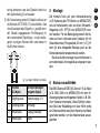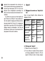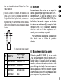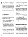
1
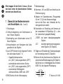
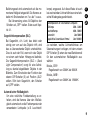
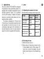
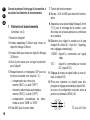
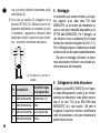
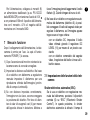
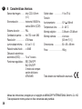
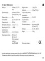
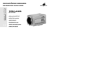
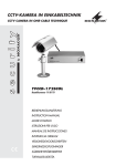
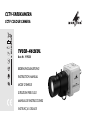
CCTV-FARBKAMERA
CCTV COLOUR CAMERA
TVCCD-462COL
Best.-Nr. 19.9330
BEDIENUNGSANLEITUNG
INSTRUCTION MANUAL
MODE D’EMPLOI
ISTRUZIONI PER L’USO
MANUAL DE INSTRUCCIONES
INSTRUKCJA OBSŁUGI
®
D
A
CH
F
B
CH
E
Bevor Sie einschalten ...
We wish you much pleasure with your new
MONACOR unit. Please read these instructions before use.
Der deutsche Text beginnt auf Seite 4.
The English text starts on page 11.
Avant toute utilisation ...
I
Prima di accendere ...
Nous vous remercions d'avoir choisi un appareil MONACOR et vous prions de lire cette
notice avant l’utilisation.
Vi auguriamo buon divertimento con il Vostro
nuovo apparecchio MONACOR. Vi preghiamo
di leggere le presenti istruzioni prima dell'uso.
La version française commence à la page 18.
Il testo italiano comincia a pagina 25.
Antes de la conexión ...
Le agradecemos el haber adquirido un aparato MONACOR. Por favor lee este manual
antes del uso.
La versión española se encuentra en la página 32.
2
GB Before you switch on ...
Wir wünschen Ihnen viel Spaß mit Ihrem
neuen Gerät von MONACOR. Bitte lesen Sie
vor dem Gebrauch diese Anleitung.
PL Przed Uruchomieniem ...
Życzymy Państwu zadowolenia z nowego urządzenia firmy MONACOR. Prosimy o zapoznanie
się z niniejsza instrukcją przed przystąpieniem
do jego użytkowania.
Tekst polski zaczyna się na stronie 39.
1
2 4
5
10
VIDEO
OFF
OFF
AWB
6
BLC
ESC
ATW
LENS
DC
VIDEO
POWER
DC LEVEL
11
7
DIGITAL CCD CAMERA
8
12
+ 12V GND
3 4
3
➀
9
AUTO IRIS
➁
D
A
Bitte klappen Sie die Seite 3 heraus. Sie sehen dann immer die beschriebenen Bedienelemente und Anschlüsse.
CH
1
Übersicht der Bedienelemente
und Anschlüsse (Abb. 1 und 2)
1 Schutzkappe
2 C-Mount-Adapterring zum Aufschrauben eines C-Mount-Objektivs
3 Gewindering zum Aufschrauben eines CSMount-Objektivs
4 Inbusschrauben zum Korrigieren des Auflagemaßes für das Objektiv
5 je ein DIP-Schalter für die folgenden Funktionen (siehe dazu Kapitel 7.1):
– Gegenlichtkompensation,
ein- („BLC“) oder ausgeschaltet („OFF“)
– automatischer elektronischer Shutter,
ein- („ESC“) oder ausgeschaltet („OFF“)
– automatischer Weißabgleich
wahlweise Modus „AWB“ oder „ATW“
6 BNC-Buchse für den Videoausgang
4
7 Betriebsanzeige
8 Klemmen +12V und GND zum Anschluss der
Stromversorgung
9 Adapter mit Gewindebuchse [Fotogewinde
6,3 mm (1/ 4")] für die Kameramontage;
kann an die Ober- oder Unterseite der Kamera geschraubt werden
10 Umschalter zur Einstellung der Kamera auf
den verwendeten AI-Objektivtyp [AI = „Auto
Iris“ (automatisch geregelte Blende)]
„VIDEO“: bei einem videosignalgeregelten
Objektiv
„DC“:
bei einem gleichspannungsgesteuerten Objektiv (DC-Objektiv)
11 Regler zum Einstellen des Videosignalpegels
bei Verwendung eines DC-Objektivs
12 Buchse für den Anschluss eines Objektivs mit
automatischer Blendenregelung (AI-Objektiv);
die Buchse hat, in Abhängigkeit des Schalters
LENS (10), die folgende Pinbelegung:
2
4
1
3
➂
Buchse AUTO IRIS
2
Pin
Schalter LENS
in Position „DC“
Schalter LENS in
Position „VIDEO“
1
Dämpfungsspule -
Stromversorgung +12 V
2
Dämpfungsspule +
nicht belegt
3
Antriebsspule +
Ausgang Videosignal
4
Antriebsspule -
Masse
Wichtige Hinweise für den
Gebrauch
Die CCTV-Kamera entspricht allen erforderlichen Richtlinien der EU und ist deshalb mit
gekennzeichnet.
●
Die Kamera ist nur zur Verwendung im Innenbereich geeignet. Bei Außenmontage muss sie
in ein wetterfestes Schutzgehäuse eingesetzt
werden.
●
Schützen Sie die Kamera vor Staub, Feuchtigkeit und Hitze (zulässiger Einsatztemperaturbereich 0 – 40 °C).
●
●
●
●
Schützen Sie den CCD-Bildaufnehmer vor
Staub und Verschmutzung und berühren Sie
ihn auf keinen Fall mit den Fingern.
Wenn kein Objektiv aufgeschraubt ist, setzen
Sie zum Schutz des CCD-Bildaufnehmers
immer die Schutzkappe (1) auf die Objektivfassung der Kamera.
Verwenden Sie für die Reinigung nur ein
trockenes, weiches Tuch, niemals Chemikalien oder Wasser.
Wird die Kamera zweckentfremdet, nicht richtig angeschlossen, falsch bedient oder nicht
fachgerecht repariert, kann keine Haftung für
daraus resultierende Sach- oder Personenschäden und keine Garantie für die Kamera
übernommen werden.
D
A
CH
Soll die Kamera endgültig aus dem
Betrieb genommen werden, übergeben
Sie sie zur umweltgerechten Entsorgung einem örtlichen Recyclingbetrieb.
5
D
3
A
Die Farbkamera TVCCD-462COL ist für den Einsatz in Video-Überwachungsanlagen konzipiert.
Sie ist mit einer Gegenlichtkompensation und
einem automatischen elektronischen Shutter
ausgestattet (ein-/ausschaltbar über DIP-Schalter). Außerdem verfügt die Kamera über einen
automatischen Weißabgleich mit zwei umschaltbaren Betriebsmodi.
Die Kamera ist für die Aufnahme von CSMount- und C-Mount-Objektiven ausgelegt. Es
können sowohl Objektive mit automatischer Blendenregelung [AI-Objektive („Auto Iris“), videosignalgeregelt oder gleichspannungsgesteuert]
als auch Objektive mit manueller Blendeneinstellung verwendet werden. Ein 4-poliger Anschlussstecker für die Blendensteuerung liegt der Kamera bei.
CH
Einsatzmöglichkeiten
4
Objektiv
4.1 Kamera auf das Objektiv einstellen
Je nach verwendetem Objektivtyp die jeweiligen
Schaltereinstellungen durchführen:
Objektivtyp
Umschalter
LENS (10)
mittlerer DIPSchalter (5)
videosignalgeregeltes Position
AI-Objektiv
„VIDEO“
Position „OFF“
gleichspannungsgesteuertes AI-Objektiv
Position
„DC“
Position „OFF“
Objektiv mit fester
oder manuell einstellbarer Blende
beliebige
Position
Position „ESC“
4.2 Objektiv montieren
1) Die Schutzkappe (1) abnehmen.
2) Bei Verwendung eines C-Mount-Objektivs dieses auf den C-Mount-Adapterring (2) schrauben. Bei einem CS-Mount-Objektiv den Adap-
6
terring entfernen und das Objektiv direkt auf
den Gewindering (3) schrauben.
3) Bei Verwendung eines AI-Objektivs dieses an
die Buchse AUTO IRIS (12) anschließen. Das
Anschlusskabel des Objektivs – gemäß der in
der Tabelle angegebenen Pin-Belegung für
den verwendeten Objektivtyp – an den beiliegenen 4-poligen Stecker löten und diesen in
die Buchse stecken.
2
4
1
3
➃
4-poliger Stecker (Lötseite)
bei einem
DC-Objektiv
bei einem videosignalgeregelten Objektiv
1
Dämpfungsspule -
Stromversorgung +12 V
2
Dämpfungsspule +
nicht belegt
3
Antriebsspule +
Ausgang Videosignal
4
Antriebsspule -
Masse
Pin
5
Montage
Die Kamera kann auf eine Kamerahalterung
(z. B. Halterung der TVH-Serie von MONACOR),
auf ein Kamerastativ oder auf einen Schwenk-/
Neigekopf (z. B. VPT-50 von MONACOR) montiert werden. Für die Befestigung besitzt die Kamera auf ihrer Unterseite einen Adapter (9) mit
Gewindebuchse [Fotogewinde 6,3 mm (1/ 4")]. Er
kann für eine hängende Montage auch an der
Kameraoberseite festgeschraubt werden.
Bei einer Außenmontage muss die Kamera in
ein wetterfestes Schutzgehäuse eingesetzt werden.
6
D
A
CH
Kamera anschließen
Die BNC-Buchse VIDEO (6) über ein 75-Ω-Kabel
(z. B. BNC-1000 von MONACOR) mit dem Videoeingang des nachfolgenden Geräts (z. B. Monitor, Kamera-Umschalter, Video-Splitter) verbinden. Bei einer Kabellänge von über 100 m sollte
ein Videoverstärker zwischen Kamera und Kabel
geschaltet werden, um die Kabelverluste auszugleichen.
7
D
A
CH
Zur Stromversorgung ein stabilisiertes Netzgerät (z. B. PS-12CCD von MONACOR) mit einer
Ausgangsspannung von 12 V und einer Belastbarkeit von 150 mA an die Klemmen (8) anschließen: Den Pluspol des Netzgeräts an die Klemme
+12V und den Minuspol des Netzgeräts an die
Klemme GND.
7
Inbetriebnahme
Nach dem Anschluss an die Stromversorgung ist
die Kamera betriebsbereit. Die Betriebsanzeige
POWER (7) leuchtet.
1) Nach dem Einschalten des Monitors die Kamera auf den Überwachungsbereich ausrichten.
2) Am Objektiv die Entfernung einstellen. Bei einem Objektiv mit manuell einstellbarer Blende
diese auf optimale Bildwiedergabe (Schärfentiefe und Helligkeit) einstellen.
3) Ist bei korrekt eingestellter Entfernung das
Bild unscharf, das Auflagemaß für das Objektiv korrigieren. Dazu mit dem beiliegenden
Inbusschlüssel die zwei Inbusschrauben (4)
8
lösen. Durch leichtes Verdrehen des Gewinderings (3) ein scharfes Bild einstellen. Anschließend die Schrauben wieder festziehen.
4) Bei einem Objektiv mit automatischer Blendenregelung (AI-Objektiv) lässt sich der Videosignalpegel für die Blendenregelung korrigieren, falls das Bild zu dunkel oder zu hell
erscheint:
Wird ein DC-Objektiv verwendet, durch
Verdrehen des Reglers DC LEVEL (11) mit
einem kleinen Schraubendreher den optimalen Videopegel einstellen.
Bei videosignalgeregelten Objektiven befindet sich der Pegelregler für das Videosignal am Objektiv.
7.1 Einstellung der Kamerafunktionen
Automatischer elektronischer Shutter (ESC)
Bei Verwendung eines Objektivs mit manueller
Blendeneinstellung den mittleren DIP-Schalter
(5) auf „ESC“ („Electronic Shutter Control“)
schieben. In dieser Position ist der automatische elektronische Shutter eingeschaltet: Die
Belichtungszeit wird automatisch auf die momentane Helligkeit eingestellt. Die Kamera arbeitet mit Shutterzeiten von 1/50 s bis 1/100 000 s.
Bei Verwendung eines AI-Objektivs den
Schalter auf „OFF“ stellen. Siehe auch Kapitel 4.1.
Gegenlichtkompensation (BLC)
Bei Gegenlicht, d. h. Licht, das direkt oder
schräg von vorn auf das Objektiv trifft, wird
das zu überwachende Objekt unterbelichtet.
Dies ist auch der Fall, wenn sich das Objekt
vor einem sehr hellen Hintergrund befindet.
Die Gegenlichtkompensation (BLC = „Back
Light Compensation“) sorgt für eine Aufhellung zu dunkel abgebildeter Objekte in der
Bildmitte. Zum Einschalten der Funktion den
oberen DIP-Schalter (5) auf Position „BLC“
stellen. Stört kein Gegenlicht, den Schalter
auf „OFF“ stellen.
lampe) angepasst. Auf diese Weise ist auch
bei wechselnden Lichtverhältnissen eine farbechte Wiedergabe gewährleistet.
Farbtemperaturen von verschiedenen Lichtquellen
Glühlampe
2800 – 3200 K
Leuchtstofflampe
4000 – 5000 K
Sonnenlicht
über 5000 K
Tageslicht bei klarem blauen Himmel
über 10 000 K
D
A
CH
Je nachdem, welche Lichtverhältnisse am
Überwachungsort vorliegen, mit dem unteren
DIP-Schalter (5) einen der zwei Betriebsmodi
für den automatischen Weißabgleich auswählen:
Modus „ATW“:
Regelbereich von 2500 K bis 9500 K
Modus „AWB“:
Regelbereich von 2000 K bis 18 000 K
Automatischer Weißabgleich
Um eine natürliche Farbdarstellung zu erhalten, wird die Kamera über den Weißabgleich automatisch an die Farbtemperatur der
verwendeten Lichtquelle (z. B. Leuchtstoff-
9
D
8
A
Bildaufnehmer: . . . . . . . CCD-Chip, 8,5 mm
(1/ 3")
Synchronisation: . . . . . . horizontal 15 625 Hz,
vertikal 50 Hz (CCIR)
Farbsystem: . . . . . . . . . PAL
Bildpunkte: . . . . . . . . . . hor. 752 x vert. 582
Auflösung: . . . . . . . . . . . 470 Linien
Mindestbeleuchtung: . . . 0,1 Lux/1 : 1,2
Signal/Rausch-Abstand > 48 dB
Autom. elektronischer
Shutter (ESC): . . . . . . . . 1/50 bis 1/100 000 s
Einstellbare Funktionen: ESC ein/aus,
BLC ein/aus,
2 Weißabgleichmodi
ATW/AWB
CH
Technische Daten
Videoausgang: . . . . . . . 1 Vss/75 Ω
Betriebsspannung: . . . . 12 V /150 mA
Einsatztemperatur: . . . . 0 – 40 °C
Objektivmontage: . . . . . C-Mount oder CSMount
Kameramontage: . . . . . über Fotogewinde
[6,3 mm (1/4")]
Abmessungen: . . . . . . . 50 × 58 × 68 mm
Gewicht: . . . . . . . . . . . . 180 g
Änderungen vorbehalten.
Diese Bedienungsanleitung ist urheberrechtlich für MONACOR ® INTERNATIONAL GmbH & Co. KG geschützt. Eine Reproduktion für eigene kommerzielle Zwecke – auch auszugsweise – ist untersagt.
10
Please unfold page 3. Then you can always
see the operating elements and connections
described.
6 BNC jack for the video output
GB
7 Power LED
8 Terminals +12 V and GND for connecting the
power supply
1
Operating Elements and Connections (fig. 1 and 2)
1 Lens cover
2 C-mount adapter ring for screwing on a
C-mount lens
3 Threaded ring for screwing on a CS-mount
lens
4 Hexagon socket screws for readjusting the
mechanical focus setting for the lens
5 One DIP switch each for the following functions (see chapter 7.1):
– backlight compensation,
activated (“BLC”) or deactivated (“OFF”)
– automatic electronic shutter,
activated (“ESC”) or deactivated (“OFF”)
– automatic white balance
two operating modes available: “AWB” or
“ATW”
9 Adapter with thread jack [thread 6.3 mm (1/ 4")]
for mounting the camera;
to be screwed on the upper or lower side of
the camera
10 Selector switch for adjusting the camera to
the AI lens type used [AI = “auto iris” (automatically controlled iris)]
“VIDEO”: for a lens controlled by video signal
“DC”:
for a DC controlled lens (DC lens)
11 Control for adjusting the video signal level
when using a DC lens
12 Jack for connecting a lens with automatic iris
control (AI lens);
depending on the switch LENS (10), the jack
has the following pin configuration:
2
4
1
3
➂
Jack AUTO IRIS
11
GB
Pin
2
Switch LENS in
position “DC”
Switch LENS in
position “VIDEO”
1
damp -
power supply +12 V
2
damp +
not connected
3
drive +
output of video signal
4
drive -
ground
Important Notes
The CCTV camera corresponds to all required
directives of the EU and is therefore marked
with .
12
●
The camera is suitable for indoor use only. For
outside installation, the camera must be mounted into a weatherproof housing.
●
Protect the camera against dust, humidity, and
heat (admissible ambient temperature range
0 – 40 °C).
●
Protect the CCD image sensor against dust
and impurities; never touch it with your fingers.
●
If no lens is mounted, always place the lens
cover (1) on the lens mount of the camera to
protect the CCD image sensor.
●
For cleaning only use a dry, soft cloth; never
use chemicals or water.
●
No guarantee claims for the unit and no liability
for any resulting personal damage or material
damage will be accepted if the camera is used
for other purposes than originally intended, if it
is not correctly connected, operated or not
repaired in an expert way.
If the camera is to be put out of operation definitively, take it to a local recycling plant for a disposal which is not
harmful to the environment.
3
Applications
The colour camera TVCCD-462COL is designed
for application in video surveillance systems. It is
equipped with a backlight compensation and an
automatic electronic shutter (to be switched
on/off via DIP switches). In addition, the camera
features an automatic white balance with two
operating modes available.
The camera is designed for CS-mount and
C-mount lenses. It is possible to use either a lens
with automatic iris control [AI (“auto iris”) lens,
controlled by video signal or DC controlled] or a
lens with manual iris control. A 4-pole connector
plug for iris control is supplied with the camera.
4
Lens
GB
4.1 Adjusting the camera to the lens
Set the switches according to the lens type used:
Lens type
Selector switch Central DIP
LENS (10)
switch (5)
AI lens controlled
by video signal
position
“VIDEO“
position “OFF”
DC controlled AI lens
position
“DC“
position “OFF”
Lens with fixed iris or
manual iris control
any
position
position “ESC”
4.2 Mounting the lens
1) Remove the lens cover (1).
2) When using a C-mount lens, screw it on the
C-mount adapter ring (2). When using a CSmount lens, remove the adapter ring and
directly screw the lens on the threaded ring
(3).
13
GB
3) When using an AI lens, connect this lens to
the jack AUTO IRIS (12). Solder the connection cable of the lens – according to the pin
configuration for the lens type used listed in
the table – to the supplied 4-pole plug, then
connect this plug to the jack.
2
4
1
3
➃
14
Mounting
The camera can be installed on a camera support (e. g. support of the MONACOR TVH-...
series), on a camera stand, or on a pan/tilt head
(e. g. MONACOR VPT-50). For this purpose, the
lower side of camera is provided with an adapter
(9) with thread jack [thread 6.3 mm (1/ 4")]. For
suspended installation, this adapter can alternatively be screwed to the upper side of the camera.
For outside installation, the camera must be
placed in a weatherproof housing.
4-pole jack (solder side)
for a DC
controlled lens
for a lens controlled
by video signal
1
damp -
power supply +12 V
2
damp +
not connected
3
drive +
output of video signal
4
drive -
ground
Pin
5
6
Connecting the Camera
Connect the BNC jack VIDEO (6) to the video
input of the following unit (e. g. monitor, camera
switcher, video splitter) via a 75 Ω cable (e. g.
MONACOR BNC-1000). With a cable length exceeding 100 m, a video amplifier should be inserted between the camera and the cable to
compensate cable loss.
For power supply, connect a regulated power
supply unit (e. g. MONACOR PS-12CCD) with
an output voltage of 12 V and a current rating
of 150 mA to the terminals (8): Connect the positive pole of the power supply unit to the terminal
+12V and the negative pole of the power supply
unit to the terminal GND.
7
Operation
After connecting the camera to the power supply,
it is ready for operation. The LED POWER (7)
lights up.
1) After switching on the monitor, adjust the
camera to the surveillance zone.
2) Adjust the distance on the lens. In case of a
lens with manual iris control, adjust the iris to
optimum picture reproduction (depth of focus
and brightness).
3) If the picture is out of focus despite a correctly
adjusted distance, readjust the mechanical
focus setting for the lens. For this purpose,
release the two hexagon socket screws (4)
with the supplied hexagon socket screw key.
Adjust a clear picture by slightly turning the
threaded ring (3). Then retighten the screws.
4) In case of a lens with automatic iris control (AI
lens), the video signal level for the iris control
can be readjusted if the picture is too dark or
too bright:
When using a DC lens, adjust the optimum
video level by turning the control DC
LEVEL (11) with a small screwdriver.
In case of a lens controlled by video signal,
the level control for the video signal can be
found on the lens.
GB
7.1 Adjustment of the camera functions
Automatic electronic shutter (ESC)
When using a lens with manual iris control,
set the central DIP switch (5) to ESC (“electronic shutter control”). In this position, the
automatic electronic shutter is switched on:
The exposure time is automatically adjusted
to the current brightness. The camera operates with shutter times of 1/50 s to 1/100 000 s.
When using an AI lens, set the switch to
“OFF”. Also see chapter 4.1.
15
GB
Backlight compensation (BLC)
In case of backlight, i. e. light which hits the
lens directly or at an angle from the front, the
object to be monitored will be underexposed.
This is also the case if the object is in front of
a very bright background. The backlight compensation (BLC) will brighten objects in the
centre of the picture which are too dark. For
activating this function, set the upper DIP
switch (5) to the position “BLC”. Without any
disturbing backlight, set the switch to “OFF”.
Automatic white balance
To obtain a natural colour reproduction, the
white balance will automatically match the
camera to the colour temperature of the light
source used (e. g. fluorescent lamp). Thus, a
faithful colour reproduction will be ensured
even in case of varying lighting conditions.
16
Colour temperatures of various light sources
Incandescent lamp
2800 – 3200 K
Fluorescent lamp
4000 – 5000 K
Sunlight
more than 5000 K
Daylight in case of a clear blue sky more than 10 000 K
According to the lighting conditions at the
place of surveillance, select one of the two
operating modes for the automatic white
balance with the lower DIP switch (5):
mode “ATW”:
control range from 2500 K to 9500 K
mode “AWB”:
control range from 2000 K to 18 000 K
8
Specifications
Image sensor: . . . . . . . . CCD chip, 8.5 mm
(1/ 3")
Sychronization: . . . . . . . horizontal 15 625 Hz,
vertical 50 Hz (CCIR)
Colour system: . . . . . . . PAL
Pixels: . . . . . . . . . . . . . . hor. 752 x vert. 582
Resolution: . . . . . . . . . . 470 lines
Minimum illumination: . . 0.1 lux/1 : 1.2
S/N ratio: . . . . . . . . . . . > 48 dB
Automatic electronic
shutter (ESC): . . . . . . . . 1/50 to 1/100 000 s
Adjustable functions: . . . ESC on/off,
BLC on/off,
2 white balance
modes ATW/AWB
GB
1 Vpp/75 Ω
12 V /150 mA
0 – 40 °C
C-mount or CS-mount
via thread
[6.3 mm (1/4")]
Dimensions: . . . . . . . . . 50 × 58 × 68 mm
Weight: . . . . . . . . . . . . . 180 g
Video output: . . . . . . . . .
Operating voltage: . . . . .
Ambient temperature: . .
Lens mount: . . . . . . . . .
Mounting of camera: . . .
Subject to technical modification.
All rights reserved by MONACOR ® INTERNATIONAL GmbH & Co. KG. No part of this instruction manual
may be reproduced in any form or by any means for any commercial use.
17
F
B
Ouvrez le présent livret page 3 de manière à
visualiser les éléments et branchements.
CH
1
Eléments et branchements
(schémas 1 et 2)
1 Bouchon d’objectif
2 Anneau adaptateur C-Mount pour visser un
objectif à filetage C-Mount
3 Anneau fileté pour visser un objectif à filetage
CS-Mount
4 Vis à 6 pans creux pour corriger la précision
pour l’objectif
5 Respectivement un interrupteur DIP pour les
fonctions suivantes (voir chapitre 7.1) :
– compensation du contre-jour,
marche (“BLC”) ou arrêt (“OFF”)
– obturation électronique automatique,
marche (“ESC”) ou arrêt (“OFF”)
– compensation automatique du blanc,
mode au choix “AWB” ou “ATW”
6 Prise BNC pour la sortie vidéo
18
7 Témoin de fonctionnement
8 Bornes +12 V et GND pour brancher l’alimentation
9 Adaptateur avec prise filetée [filetage 6,3 mm
(1/ 4")] pour le montage de la caméra : peut
être vissé sur la face supérieure ou inférieure
de la caméra.
10 Sélecteur pour régler la caméra sur le type
d’objectif AI utilisé (AI : “Auto Iris” : diaphragme à réglage automatique))
“VIDEO” : objectif à commande par signal
vidéo
“DC” :
objectif à commande par tension
DC (objectif DC)
11 Réglage du niveau du signal vidéo si vous utilisez un objectif DC
12 Prise pour brancher un objectif avec diaphragme à réglage automatique (objectif AI) :
la prise a la configuration suivante selon la
position du sélecteur LENS (10) :
2
4
1
3
➂
prise AUTO IRIS
Pin
2
Sélecteur LENS
sur position “DC”
Sélecteur LENS
sur position “VIDEO”
1
bobine atténuation - alimentation +12 V
2
bobine atténuation + non configuré
3
bobine moteur +
sortie signal vidéo
4
bobine moteur -
masse
●
Si aucun objectif n’est vissé, placez toujours le
bouchon d’objectif (1) sur la monture d’objectif
de la camera pour protéger la puce CCD .
●
Pour la nettoyer, utilisez un chiffon sec et doux,
en aucun cas de produits chimiques ou d’eau.
●
Nous déclinons toute responsabilité en cas de
dommages corporels ou matériels résultants si
la caméra est utilisée dans un but autre que
celui pour lequel elle a été conçue, si elle n’est
pas correctement branchée, utilisée ou n’est
pas réparée par une personne habilitée, de
même, la garantie deviendrait caduque.
Conseils importants d’utilisation
La caméra CCTV répond à toutes les directives
nécessaires de l’Union Européenne et porte
donc le symbole .
● La caméra n’est conçue que pour une utilisation en intérieur. Pour un montage en extérieur, elle doit être placée dans un boîtier de
protection étanche.
● Protégez la caméra de la poussière, de l’humidité et de la chaleur (plage de température de
fonctionnement autorisée : 0 °C à +40 °C).
● Protégez la puce CCD de la poussière et des
salissures, en aucun cas, vous ne devez la
toucher avec les doigts.
F
B
CH
Lorsque la caméra est définitivement
retirée du marché, vous devez la déposer dans une usine de recyclage de
proximité pour contribuer à son élimination non polluante.
3
Possibilités d’utilisation
La caméra couleur TVCCD-462COL est spécialement conçue pour une utilisation dans des
installations de surveillance vidéo. Elle est
19
F
B
CH
équipée d’une compensation du contre-jour et
d’une obturation électronique automatique (marche/arrêt par interrupteurs DIP). En outre, elle
dispose d’une compensation automatique du
blanc avec deux modes de fonctionnement commutables.
La caméra est conçue pour des objectifs de
type C-Mount ou CS-Mount. Il est possible d’utiliser des objectifs à réglage automatique de diaphragme (objectifs AI [“Auto Iris”], à réglage par
signal vidéo ou par tension DC) et des objectifs à
réglage manuel de diaphragme. Une fiche de
branchement 4 pôles pour la commande de diaphragme est livrée avec la caméra.
4
Objectif
4.1 Réglage de la caméra sur l’objectif utilisé
Selon le type d’objectif utilisé, effectuez les
réglages suivants :
Type d’objectif
Sélecteur
LENS (10)
Interrupteur DIP
médian (5)
Objectif AI à réglage
par signal vidéo
position
“VIDEO”
position “OFF”
Objectif AI à réglage
par tension DC
position
“DC”
position “OFF”
Objectif à réglage
manuel de diaphragme ou fixe
position au
choix
position “ESC”
4.2 Montage de l’objectif
1) Retirez le bouchon d’objectif (1).
2) Si vous utilisez un objectif C-Mount, vissez-le
sur l’anneau adaptateur C-Mount (2). Pour un
objectif CS-Mount, retirez l’anneau adapta-
20
teur et vissez directement l’objectif sur l’anneau fileté (3).
3) Si vous utilisez un objectif AI, reliez-le à la
prise AUTO IRIS (12). Soudez le cordon de
l’objectif à la fiche 4 pôles livrée, selon la configuration de pin mentionnée dans le tableau
pour le type d’objectif utilisé, et placez-la dans
la prise.
2
4
1
3
➃ prise 4 pôles (côté à souder)
Pin
Objectif “DC”
Objectif à réglage
par signal vidéo
1
bobine atténuation - alimentation +12 V
2
bobine atténuation + non configuré
3
bobine moteur +
sortie signal vidéo
4
bobine moteur -
masse
5
Montage
La caméra peut être montée sur un support de
caméra (par exemple support de la série TVH-…
de MONACOR), un pied de caméra ou sur un
rotor (par exemple VPT-50 de MONACOR). Pour
la fixation, la caméra dispose sur la face
inférieure d’un adaptateur (9) avec prise filetée
[filetage 6,3 mm (1/ 4")]. Il peut être également
vissé au choix sur la face supérieure de la
caméra pour un montage suspendu.
Pour un montage en extérieur, la caméra doit
être placée dans un boîtier de protection
étanche.
6
F
B
CH
Branchements de la caméra
Reliez la prise BNC VIDEO (6) via un cordon
75 Ω (par exemple BNC-1000 de MONACOR) à
l’entrée vidéo de l’appareil suivant (par exemple,
moniteur, sélecteur de caméra, collecteur vidéo
pour affichage simultané). Pour une longueur de
câble supérieure à 100 m, il convient de placer
un amplificateur vidéo entre la caméra et le câble
pour compenser les pertes en ligne.
21
F
B
CH
Pour l’alimentation de la caméra, une alimentation stabilisée (par exemple PS-12CCD de
MONACOR) avec une tension de sortie de
12 V et une consommation de 150 mA doit être
reliée aux bornes (8) : Reliez le pôle plus de l’alimentation à la borne +12V et le pôle moins de
l’alimentation à la borne GND.
7
Fonctionnement
Une fois le branchement à l’alimentation effectué, la caméra est prête à fonctionner. Le témoin
de fonctionnement POWER (7) brille.
1) Une fois le moniteur allumé, dirigez la caméra
sur la zone à surveiller.
2) Sur l’objectif, réglez la distance. Pour un objectif à diaphragme à réglage manuel, réglez
le diaphragme pour une restitution optimale
des images (profondeur de champ et luminosité).
3) Si pour une distance correctement réglée,
l’image n’est pas nette, corrigez la précision
pour l’objectif. Pour ce faire, avec la clé livrée,
desserrez les deux vis à 6 pans creux (4). En
22
tournant légèrement l’anneau fileté (3), réglez
une image nette. Revissez ensuite les vis.
4) Pour un objectif à commande automatique de
diaphragme (objectif AI), le niveau du signal
vidéo pour le réglage du diaphragme peut
être corrigé si l’image est trop sombre ou trop
claire :
Si un objectif DC est utilisé, réglez le
niveau vidéo optimal en tournant le réglage
DC LEVEL (11) avec un petit tournevis.
Pour des objectifs à commande par signal
vidéo, le réglage de niveau pour le signal
vidéo se trouve sur l’objectif.
7.1 Réglage des fonctions de la caméra
Obturation électronique automatique (ESC)
Si vous utilisez un objectif à réglage manuel
de diaphragme, mettez l’interrupteur DIP du
milieu (5) sur “ESC” (“Electronic Shutter Control”). Dans cette position, l’obturation électronique automatique est allumée : la durée
d’exposition est réglée automatiquement sur
la luminosité du moment. La caméra fonc-
tionne avec des durées d’obturation de 1/50 s –
1/100 000 s.
Si vous utilisez un objectif AI, mettez l’interrupteur sur “OFF”. Voir également chapitre
4.1.
Compensation du contre-jour (BLC)
En cas de contre-jour, c’est-à-dire lorsque la
lumière touche l’objectif directement ou en
oblique par l’avant, l’objet à surveiller est
sous-exposé. C’est aussi le cas lorsque l’objet se trouve devant un fond très clair. La compensation du contre-jour (BLC : “Back Light
Compensation”) génère un éclaircissement
pour les objets affichés trop sombres dans la
partie centrale de l’image. Pour allumer cette
fonction, mettez l’interrupteur DIP supérieur
(5) sur la position “BLC”. Si aucun contre-jour
perturbateur n’est présent, mettez l’interrupteur sur “OFF”.
neuse utilisée (par exemple lampe fluorescente). De cette façon, on garantit une restitution fidèle des couleurs même en cas de conditions d’éclairage changeantes.
F
B
CH
Températures de couleur de diverses sources lumineuses
Lampe à incandescence
2800 – 3200 K
Lampe fluorescente
4000 – 5000 K
Lumière du soleil
au-dessus de 5000 K
Lumière du jour avec ciel
clair et bleu
au-dessus de 10 000 K
Selon les conditions d’éclairage présentes
sur le lieu de surveillance, sélectionnez avec
l’interrupteur DIP inférieur (5) un des deux
modes de fonctionnement pour la compensation automatique du blanc :
mode “ATW” :
plage de réglage de 2500 K à 9500 K
mode “AWB” :
plage de réglage de 2000 K à 18 000 K
Compensation automatique du blanc
Pour obtenir une reproduction naturelle des
couleurs, la caméra est adaptée via la compensation du blanc, automatiquement à la
température de couleur de la source lumi-
23
F
8
B
Système : . . . . . . . . . . . puce CCD, 8,5 mm
(1/ 3")
Synchronisation : . . . . . horizontal 15 625 Hz,
vertical 50 Hz (CCIR)
Système couleur : . . . . . PAL
Nombre de points : . . . . hor. 752 x vert. 582
Résolution : . . . . . . . . . . 470 lignes
Luminosité minimale : . . 0,1 lux/1 : 1,2
Rapport signal/bruit : . . > 48 dB
Obturation électronique
automatique (ESC) : . . . 1/50 à 1/100 000 s
Fonctions réglables : . . . ESC marche/arrêt
BLC marche/arrêt
2 modes de compensation du blanc
ATW/AWB
CH
Caractéristiques techniques
Sortie vidéo : . . . . . . . . . 1 Vcc/75 Ω
Tension fonctionnement : 12 V /150 mA
Température fonc. : . . . . 0 – 40 °C
Montage objectif : . . . . . C-Mount ou CS-Mount
Montage caméra : . . . . . par filetage
[6,3 mm (1/ 4")]
Dimensions : . . . . . . . . . 50 × 58 × 68 mm
Poids : . . . . . . . . . . . . . . 180 g
Tout droit de modification réservé.
Notice d'utilisation protégée par le copyright de MONACOR ® INTERNATIONAL GmbH & Co. KG.
Toute reproduction même partielle à des fins commerciales est interdite.
24
Vi preghiamo di aprire completamente la
pagina 3. Così vedrete sempre gli elementi di
comando e i collegamenti descritti.
6 Presa BNC per l’uscita video
I
7 Spia di funzionamento
8 Morsetti +12 V e GND per il collegamento
dell’alimentazione
1
Elementi di comando e collegamenti (figg. 1 e 2)
1 Cappuccio protettivo
2 Anello adattatore C-Mount per avvitare un
obiettivo C-Mount
9 Adattatore con presa filettata [tipo macchina
fotografica 6,3 mm (1/ 4")] per il montaggio
della telecamera;
può essere avvitato sul lato superiore o inferiore della telecamera
3 Anello filettato per avvitare un obiettivo CSMount
10 Selettore per regolare la telecamera secondo
il tipo di obiettivo AI [AI = “Auto Iris” (diaframma regolato automaticamente)]
4 Viti ad esagono cavo per correggere la posizione dell’obiettivo
“VIDEO”: con obiettivo comandato dal segnale video
5 Dip-switch per le seguenti funzioni (vedi
anche cap. 7.1):
– compensazione della controluce
attivata (“BLC”) o disattivata (“OFF”)
– shutter elettronico automatico
attivato (“ESC”) o disattivato (“OFF”)
– bilanciamento automatico del bianco
a scelta modalità “AWB” o “ATW”
“DC”:
con obiettivo comandato dalla tensione continua (obiettivo DC)
11 Regolatore per impostare il livello del segnale
video con l’uso di un obiettivo DC
12 Presa per il collegamento di un obiettivo con
regolazione automatica del diaframma (obiettivo AI); i contatti dei pin sono, a seconda della
posizione del selettore LENS (10), i seguenti:
25
I
1
3
2
4
Pin
2
➂
Proteggere il sensore ottico CCD dalla polvere
e dallo sporco; non toccarlo in nessun caso
con le dita.
●
Se non è montato nessun obiettivo inserire
sempre il cappuccio protettivo (1) sul portaobiettivo per proteggere il sensore ottico.
●
Per la pulizia usare solo un panno asciutto,
morbido, mai prodotti chimici o acqua.
●
Nel caso d’uso improprio, di collegamenti sbagliati, di impiego scorretto o di riparazione non
a regola d’arte della telecamera, non si assume nessuna responsabilità per eventuali
danni consequenziali a persone o a cose e non
si assume nessun garanzia per la telecamera.
Presa AUTO IRIS
Selettore LENS
in posizione “DC”
Selettore LENS in
posizione “VIDEO”
1
bobina di attenuazione -
alimentazione +12 V
2
bobina di attenuazione +
libero
3
bobina di azionamento +
uscita segnale video
4
bobina di azionamento -
massa
Avvertenze importanti per l’uso
La telecamera CCTV è conforme a tutte le direttive richieste dell’UE e pertanto porta la sigla .
26
●
●
La telecamera è adatta solo per l’uso all’interno di locali. Nel caso di montaggio all’esterno deve essere montata in una custodia
resistente alle intemperie.
●
Proteggere la telecamera dalla polvere, dall’umidità e dal calore (temperatura d’impiego
ammessa 0 – 40 °C).
Se si desidera eliminare la telecamera
definitivamente, consegnarla per lo
smaltimento ad un’istituzione locale per
il riciclaggio.
3
Possibilità d’impiego
La telecamera a colori TVCCD-462COL è stata
realizzata per l’impiego in impianti di sorveglianza video. È equipaggiata con una compensazione della controluce e con un otturatore elettronico automatico (dis/attivabile tramite dip-switch).
La telecamera dispone inoltre di bilanciamento
automatico del bianco con due modalità di funzionamento.
Sulla telecamera si possono montare sia
obiettivo CS-mount che C-mount. Gli obiettivi
possono essere usati con regolazione automatica del diaframma [obiettivi AI (“Auto Iris”), con
regolazione dal segnale video o dalla tensione
continua] oppure con regolazione manuale del
diaframma. Un connettore a 4 poli per comandare il diaframma è in dotazione.
4
Obiettivo
I
4.1 Regolare la telecamera a seconda
dell’obiettivo
Eseguire le diverse impostazioni dei selettori a
seconda del tipo di obiettivo usato:
Tipo di obiettivo
Selettore
LENS (10)
DIP-switch
centrale (5)
Obiettivo AI comandato
dal segnale video
posizione
“VIDEO“
posizione “OFF”
Obiettivo AI comandato
dalla tensione continua
posizione
“DC“
posizione “OFF”
Obiettivo con diaqualsiasi
framma fisso o manuale posizione
posizione “ESC”
4.2 Montaggio dell’obiettivo
1) Togliere il cappuccio protettivo (1).
2) Usando un obiettivo C-mount, avvitarlo sull’anello adattatore C-mount (2). Nel caso di un
obiettivo CS-mount, togliere l’anello adatta-
27
I
tore e avvitare l’obiettivo direttamente sull’anello filettato (3).
3) Se si usa un obiettivo AI, collegarlo con la
presa AUTO IRIS (12). Saldare il cavo di collegamento dell’obiettivo al connettore a 4 poli
in dotazione – seguendo le indicazioni della
tabella dei contatti in relazione al tipo di obiettivo – e inserire il connettore nella presa.
2
4
1
3
➃
Pin
28
con obiettivo DC
Connettore a 4 poli (lato a
saldare)
con obiettivo regolato dal segnale video
1
bobina di attenuazione - alimentazione +12 V
2
bobina di attenuazione + libero
3
bobina di azionamento + uscita segnale video
4
bobina di azionamento - massa
5
Montaggio
La telecamera può essere montata su un apposito supporto (p. es. della serie TVH della
MONACOR), su uno stativo per telecamere oppure su una testa orientabile/ basculabile (p. es.
VPT-50 della MONACOR). Per il fissaggio, sul
lato inferiore si trova un adattatore (9) con presa
filettata [tipo macchina fotografica 6,3 mm (1/ 4")].
Per il montaggio sospeso, l’adattatore può essere
avvitato anche sul lato superiore della telecamera.
Nel caso di montaggio all’esterno, la telecamera deve essere montata in una custodia protettiva resistente alle intemperie.
6
Collegamento della telecamera
Collegare la presa BNC VIDEO (6) con l’ingresso video dell’apparecchio a valle (p. es. monitor,
selettore per telecamere, video-splitter) servendosi di un cavo 75 Ω (p. es. BNC-1000 della
MONACOR). Se il cavo supera i 100 metri di
lunghezza, è opportuno inserire un amplificatore
video fra telecamera e cavo per compensare le
perdite dovute al cavo.
Per l’alimentazione, collegare ai morsetti (8)
un alimentatore stabilizzato (p. es. PS-12CCD
della MONACOR) con tensione d’uscita di 12 V
e con potenza di 150 mA: il positivo dell’alimentatore con il morsetto +12 V e il negativo dell’alimentatore con il morsetto GND.
7
Messa in funzione
Dopo il collegamento dell’alimentazione, la telecamera è pronta per l’uso. La spia di funzionamento POWER (7) è accesa.
1) Dopo l’accensione del monitor orientare la telecamera verso la zona da sorvegliare.
2) Impostare la distanza sull’obiettivo. Nel caso
di un obiettivo con diaframma a regolazione
manuale impostare il diaframma per una
riproduzione ottimale dell’immagine (profondità di campo e luminosità).
3) Se con distanza impostata correttamente,
l’immagine non è a fuoco, occorre correggere
la posizione del obiettivo. Per fare ciò allentare le due viti esagonali cavi (4) per mezzo
dell’apposita chiave in dotazione. Mettere a
fuoco l’immagine girando leggermente l’anello
filettato (3). Quindi stringere di nuovo le viti.
I
4) Nel caso di un obiettivo con regolazione automatica del diaframma (obiettivo AI), è possibile correggere il livello del segnale video per
regolare il diaframma, se l’immagine appare
troppo scura o troppo chiara:
con un obiettivo DC, impostare il livello
video ottimale girando il regolatore DC
LEVEL (11) per mezzo di un piccolo cacciavite
con un obiettivo comandato dal segnale
video, il regolatore del livello si trova sull’obiettivo stesso.
7.1 Impostazione delle funzioni della telecamera
Shutter elettronico automatico (ESC)
Se si usa un obiettivo con regolazione manuale del diaframma, spostare il dip-switch
centrale (5) su “ESC” (“Electronic Shutter
Control”). In questa posizione, lo shutter
elettronico automatico è attivato: il tempo di
29
I
esposizione viene regolato automaticamente
secondo la luminosità presente. I tempi di
esposizione vanno da 1/50 s bis 1/100 000 s.
Se si usa un obiettivo AI, mettere lo switch
su “OFF”. Vedi anche capitolo 4.1.
Compensazione della controluce (BLC)
Nel caso di controluce, cioè di luce che colpisce l’obiettivo direttamente o di sbieco dal davanti, l’oggetto da sorvegliare sarà sottoesposto. Lo stesso succede se l’oggetto si trova
davanti a uno sfondo molto chiaro. La compensazione della controluce (BLC = “Back
Light Compensation”) provvede a rendere più
chiare le parti scure nel centro dell’immagine.
Per attivare la funzione, portare il dip-switch
superiore (5) su “BLC”. Nel caso di assenza di
controluce mettere lo switch su “OFF”.
Bilanciamento automatico del bianco
Per ottenere delle immagini con colori naturali, la telecamera si adatta automaticamente
alla temperatura cromatica della sorgente di
luce (p. es. lampada fluorescente) per mezzo
del bilanciamento del bianco. In questo modo,
30
anche con condizioni di luce variabili sono
garantiti colori naturali dell’immagine.
Temperature cromatiche di differenti sorgenti di luce
Lampada ad incandescenza
2800 – 3200 K
Lampada fluorescente
4000 – 5000 K
Luce del sole
oltre 5000 K
Luce del giorno con cielo sereno
oltre 10 000 K
Selezionare con il dip-switch inferiore (5) una
delle due modalità di bilanciamento del bianco a seconda delle condizioni di luce presenti
sul luogo da sorvegliare:
Modalità “ATW”:
Campo di regolazione da 2500 K a 9500 K
Modalità “AWB”:
Campo di regolazione da 2000 K a 18 000 K
8
Dati tecnici
Sensore ottico: . . . . . . . chip CCD, 8,5 mm
(1/ 3")
Sincronizzazione: . . . . . orizzontale 15 625 Hz,
verticale 50 Hz (CCIR)
Sistema di colore: . . . . . PAL
Pixel: . . . . . . . . . . . . . . . orizz. 752 x vert. 582
Risoluzione: . . . . . . . . . 470 linee
Illuminazione minima: . . 0,1 Lux/1 : 1,2
Rapporto S/R: . . . . . . . . > 48 dB
Shutter elettronico
automatica (ESC): . . . . . 1/50 a 1/100 000 s
Funzioni impostabili: . . . ESC on/off,
BLC on/off,
2 mod. di bilanciamento del bianco
ATW/AWB
I
1 Vpp/75 Ω
12 V /150 mA
0 – 40 °C
C-Mount o CS-Mount
tramite filettatura tipo
macchina fotografica
[6,3 mm (1/ 4")]
Dimensioni: . . . . . . . . . . 50 × 58 × 68 mm
Peso: . . . . . . . . . . . . . . . 180 g
Uscita video: . . . . . . . . .
Tensione d’esercizio: . . .
Temperatura d’esercizio:
Montaggio obiettivo: . . .
Montaggio telecamera: .
Con riserva di modifiche tecniche.
La MONACOR ® INTERNATIONAL GmbH & Co. KG si riserva ogni diritto di elaborazione in qualsiasi forma
delle presenti istruzioni per l’uso. La riproduzione – anche parziale – per propri scopi commerciali è vietata.
31
E
Abrir el presente libro página 3 de manera a
visualizar los elementos y las conexiones.
1
Elementos y conexiones
(esquema 1 y 2)
1 Tapa de protección
2 Anilla adaptadora C-Mount para atornillar un
objetivo con rosca C-Mount
3 Anilla enroscada para atornillar un objetivo
con rosca CS-Mount
4 Tornillos de cabeza con hexágono interior
para corregir la precisión del objetivo
5 Respectivamente un interruptor DIP para las
funciones siguientes (vea capítulo 7.1):
– compensación de la contraluz, conectado
(“BLC”) o desconectado (“OFF”)
– obturación electrónica automática, conectado (“ESC”) o desconectado (“OFF”)
– compensación automática del blanco,
modo a elegir “AWB” o “ATW”
6 Toma BNC para la salida video
32
7 Testigo de funcionamiento
8 Bornes +12V y GND para conectar la alimentación
9 Adaptador con toma enroscada [rosca
6,3 mm (1/ 4")] para el montaje de la cámara;
puede atornillarla en la parte superior o en la
parte inferior de la cámara
10 Selector para regular la cámara en el tipo de
objetivo AI utilizado [AI = “Auto Iris” (diafragma con reglaje automático)]
“VIDEO”: en caso de un objetivo con reglaje
por señal video
“DC”:
en caso de un objetivo con control
por tensión DC (objetivo DC)
11 Reglaje del nivel de la señal video si utiliza un
objetivo DC
12 Toma para conectar un objetivo con reglaje
automático de diafragma (objetivo AI); la
toma tiene la configuración siguiente según la
posición del selector LENS (10):
2
4
1
3
➂
Toma AUTO IRIS
Pin
2
Selector LENS
en posición “DC”
Selector LENS
en posición “VIDEO”
1
bobina atenuación - alimentación +12 V
2
bobina atenuación + no configurada
3
bobina motor +
salida señal video
4
bobina motor -
masa
Notas importantes
La cámara corresponde a todas las Directivas requeridas de la UE y por ello está marcada con .
●
La cámara está fabricada únicamente para
una utilización en interior. Para un montaje en
exterior, debe colocarla en una caja de protección resistente a la intemperie.
●
Protéjela del polvo, de la humedad y del calor
(temperatura de funcionamiento autorizada:
0 °C a +40 °C).
●
Proteja el sensor CCD del polvo y de las salpicaduras, en ningún caso, no la manipule con
los dedos.
●
●
●
Si ningún objetivo está atornillado, coloque
siempre la tapa de protección (1) sobre el
zócalo del objetivo de la cámara para proteger
el sensor CCD.
Para limpiar la cámara, utilice un trapo seco y
suave, en ningún caso productos químicos o
agua.
Rechazamos cualquier responsabilidad en caso de daños corporales o materiales que resultarían de una utilización inadecuada y diferente de la utilización para la cual la cámara ha
sido fabricada, si no está correctamente conectada o reparada por una persona especializada, además por todos estos mismos motivos
el aparato carecería de todo tipo de garantía.
E
Cuando la cámara está definidamente
sacada del servicio, debe depositarla
en una fábrica de reciclaje de proximidad para contribuir a una eliminación
no contaminante.
33
E
3
Posibilidades de utilización
La cámara color TVCCD-462COL está especialmente fabricada para una utilización en instalaciones de vigilancia video. Dispone de la compensación de la contraluz, de una obturación
electrónica automática (ON/OFF por interruptores DIP). También dispone de una compensación automática del blanco con dos modos de
funcionamiento conmutables.
La cámara está fabricada para objetivos de
tipo C-Mount o CS-Mount. Es posible utilizar
objetivos con reglaje automático de diafragma
[objetivo AI (“Auto Iris”), con reglaje por señal
video o con control por tensión DC] así como
objetivos con reglaje manual de diafragma. Una
toma de conexión 4 polos para el control de
diafragma está entregada con la cámara.
4
Objetivo
4.1 Reglaje de la cámara según el objetivo
Según el tipo de objetivo utilizado, efectué los
reglajes siguientes:
Tipo objetivo
Selector
(10) LENS
Interruptor DIP
(5), del medio
Objetivo AI con reglaje por señal video
posición
“VIDEO”
posición “OFF”
Objetivo AI con control por tensión DC
posición
“DC”
posición “OFF”
Objetivo con
diafragma a reglaje
manual o fijo
posición
indiferente
posición “ESC”
4.2 Montaje del objetivo
1) Saque la tapa de protección (1).
2) Si utiliza un objetivo C-Mount, atorníllelo
sobre la anilla adaptadora C-Mount (2). Para
un objetivo CS-Mount, saque la anilla adapta-
34
dora y atornille directamente el objetivo sobre
la anilla enroscada (3).
3) Si utiliza un objetivo AI, conéctelo con la toma
AUTO IRIS (12). Soldar el cable del objetivo
con la toma 4 polos entregada, según la configuración de pin mencionada en la tabéela
para el tipo de objetivo utilizado, y colóquelo
en la toma AUTO IRIS.
2
4
1
3
➃
en caso de un
Pin
objetivo “DC”
Toma 4 polos (lado a soldar)
en caso de un objetivo con
reglaje por señal video
1
bobina atenuación - alimentación +12 V
2
bobina atenuación + no configurada
3
bobina motor +
salida señal video
4
bobina motor -
masa
5
Montaje
E
Puede montar la cámara sobre un soporte de
cámara (p. ej. los soportes de la serie TVH-… de
MONACOR), sobre un pie de cámara o sobre un
rotor (p. ej. VPT-50 de MONACOR). Para la fijación, la cámara dispone en la parte inferior de un
adaptador (9) con una toma enroscada [rosca
6,3 mm (1/ 4")]. También puede atornillarlo en la
parte superior de la cámara para un montaje colgado.
Para un montaje en exterior, debe colocar la
cámara en una caja de protección resistente a la
intemperie.
6
Conexiones de la cámara
Conecte la toma BNC VIDEO (6) vía un cable
75 Ω (por ejemplo BNC-1000 de MONACOR)
con la entrada video del aparato siguiente (por
ejemplo, monitor, selector de cámara, colector
video para visualización simultánea). Para una
longitud de cable superior a 100 m, conviene
colocar un amplificador video entre la cámara y
el cable para compasar las perdidas en línea.
35
E
Para la alimentación de la cámara, una alimentación estabilizada (p. ej. PS-12CCD de
MONACOR) con una tensión de salida de 12 V
y una capacidad de corriente de 150 mA debe
conectarse a los bornes (8): conecte el polo
positivo de la alimentación al borne +12V y el
polo negativo de la alimentación al borne GND.
7
Funcionamiento
Una vez la conexión a la alimentación efectuada,
la cámara está lista a funcionar. El testigo de funcionamiento POWER (7) brilla.
1) Una vez el monitor conectado, dirija la cámara hacia la zona de vigilancia.
2) En el objetivo, regule la distancia. Para un
objetivo con diafragma a reglaje manual, regule el diafragma para una restitución óptima
de las imágenes (profundidad de campo y
luminosidad).
3) Si para una distancia correctamente regulada, la imagen no es nítida, corrija la precisión del objetivo. Para efectuar esta manipulación, con la llave entregada, desatornille los
36
dos tornillos de cabeza con hexágono interior
(4). Girando ligeramente la anilla enroscada
(3), regule una imagen nítida. Atornille de
nuevo los tornillos.
4) Para un objetivo con reglaje automático de
diafragma (objetivo AI), el nivel de la señal
video para el reglaje del diafragma puede corregirse si la imagen es demasiada oscura o
demasiada clara:
Si utiliza un objetivo DC, regule el nivel
video óptimo girando el reglaje DC LEVEL
(11) con un pequeño atornillador.
Para objetivos con reglaje por señal video,
el reglaje de nivel para la señal video está
en el objetivo.
7.1 Reglaje de las funciones de la cámara
Obturación electrónica automática (ESC)
Si utiliza un objetivo con reglaje manual de
diafragma, ponga el interruptor DIP del medio
(5) en “ESC” (“Electronic Shutter Control”).
En esta posición, la obturación electrónica
automática está conectada: la duración de
exposición está regulada automáticamente
en la luminosidad del momento. La cámara
funciona con duraciones de obturación de
1/50 s – 1/100 000 s.
Si utiliza un objetivo AI, ponga el interruptor
en “OFF”. Vea también capítulo 4.1.
Compensación de la contraluz (BLC)
En caso de contraluz, es decir, cuando la luz
toca el objetivo directamente o en obliga por
la parte delantera, el objeto a vigilar está subexpuesto. También es el caso cuando el
objeto está delante de un fondo muy claro. La
compensación de la contraluz (BLC: “Back
Light Compensation”) genera un esclarecimiento para los objetos demasiados oscuros
en la parte central de la imagen. Para conectar esta función, ponga el interruptor DIP
superior (5) en la posición “BLC”. Si no hay
ningún tipo de contraluz, ponga el interruptor
en “OFF”.
peratura del color de la fuente de luz utilizada
(por ejemplo lámpara fluorescente). De esta
manera, se garantiza una restitución sólida
de los colores mismo en caso de cambios de
relaciones luminosas.
E
Temperaturas de color de diversas fuentes de luz
Lámpara incandescente
2800 – 3200 K
Lámpara fluorescente
4000 – 5000 K
Luz del sol
por encima de 5000 K
Luz del día con
cielo claro y azul
por encima de 10 000 K
Según el tipo de relaciones luminosas presentes en el lugar de vigilancia, seleccione
con el interruptor DIP inferior (5) uno de los
dos modos de funcionamiento para la compensación automática del blanco:
modo “ATW”:
zona de reglaje de 2500 K a 9500 K
modo “AWB”:
zona de reglaje de 2000 K a 18 000 K
Compensación automática del blanco
Para obtener una reproducción natural de los
colores, la cámara se adapta vía la compensación del blanco, automáticamente a la tem-
37
E
8
Características técnicas
Sensor de imagen: . . . . chip CCD, 8,5 mm
(1/ 3")
Sincronización: . . . . . . . horizontal 15 625 Hz,
vertical 50 Hz (CCIR)
Sistema de color: . . . . . PAL
Cantidad de puntos: . . . hor. 752 x vert. 582
Resolución: . . . . . . . . . . 470 líneas
Luminosidad mínima: . . 0,1 lux/1 : 1,2
Relación señal/ruido: . . > 48 dB
Obturación electrónica
automática (ESC): . . . . . 1/50 a 1/100 000 s
Funciones regulables: . . ESC ON/OFF
BLC ON/OFF
2 modos de compensación del blanco
ATW/AWB
Salida video: . . . . . . . .
Tensión
funcionamiento: . . . . . .
Temperatura func.: . . . .
Montaje objetivo: . . . . .
Montaje cámara: . . . . .
1 Vcc/75 Ω
12 V /150 mA
0 – 40 °C
C-Mount o CS-Mount
vía rosca
[6,3 mm (1/4")]
Dimensiones: . . . . . . . . 50 × 58 × 68 mm
Peso: . . . . . . . . . . . . . . 180 g
Todo derecho de modificación reservado.
Manual de instrucciones protegido por el copyright de MONACOR ® INTERNATIONAL GmbH & Co. KG.
Toda reproducción mismo parcial con fines comerciales está prohibida.
38
Proszę otworzyć niniejszą instrukcję na
stronie 3. Dzięki temu będą Państwo mogli
obserwować opisywane elementy sterujące i połączenia.
1
Elementy sterujące i połączenia
(rys.1 i 2)
1 Osłona obiektywu
2 Pierścień mocujący typu C do montowania
obiektywu przystosowanego do tego obiektywu
3 Pierścień mocujący obiektywu typu CS
4 Śruby regulacji ręcznej ogniskowej obiektywu
5 Przełączniki DIP. Każdy do włączania, lub
wyłączania poszczególnych funkcji (patrz
rozdz. 7.1):
– kompensata jasnego tła,
włączona (“BLC”), lub wyłączona (“OFF”)
– automatyczna migawka,
włączona (“ESC”), lub wyłączona (“OFF”)
– automatyczna regulacji bieli
możliwe dwa tryby pracy: “AWB”, lub “ATW”
6 Gniazdo wyjścia video BNC
7 Dioda wskaźnika zasilania
8 Terminale +12V i uziemienia GND do podłączenia zasilania
9 Mocowanie kamery [śruba 6,3 mm (1/ 4")];
możliwość instalacji u dołu, lub na górze
kamery
10 Przełącznik trybu pracy z odpowiednim
obiektywem AI [AI = “auto iris” (automatyczna przesłona)]
“VIDEO”: dla obiektywów regulowanych sygnałem video
“DC”:
dla obiektywów sterowanych napięciem (obiektyw DC)
11 Regulator poziomu sygnału video podczas
używania obiektywu DC
12 Gniazdo podłączania obiektywu z automatyczną przesłoną (obiektyw AI); w zależności od
ustawienia przełącznika LENS (10), gniazdo
posiada następującą konfigurację biegunów:
2
4
1
3
➂
PL
Gniazdo AUTO IRIS
39
PL
Pin
2
Przełącznik LENS
w pozycji “DC”
Przełącznik LENS
w pozycji “VIDEO”
1
damp -
zasilanie +12 V
2
damp +
brak funkcji
3
drive +
wyjście sygnału video
4
drive -
masa
Bezpieczeństwo użytkowania
Urządzenie spełnia wymogi dyrektyw obowiązujących w Unii Europejskiej, posiada więc
oznaczenie .
● Urządzenie przeznaczone jest do użytku tylko
wewnątrz pomieszczeń. W przypadku instalacji na zewnątrz, kamera musi być
umieszczona w wodoszczelnej obudowie.
● Należy chronić je przed kurzem, wilgocią oraz
wysoką temperaturą (dopuszczalna temperatura otoczenia pracy wynosi 0 – 40 °C).
40
●
Należy chronić sensor CCD przed kurzem
oraz zanieczyszczeniami; nie wolno dotykać
go palcami.
●
Jeżeli do kamery nie jest zamocowany obiektyw należy zasłonić otwór pokrywą ochronną
(1) w celu ochrony sensora CCD.
●
Do czyszczenia używać jedynie suchego,
czystego kawałka materiału. Nie używać
środków chemicznych, ani wody.
●
Dostawca oraz producent nie ponoszą odpowiedzialności za ewentualnie wynikłe szkody
materialne lub uszczerbki na zdrowiu, jeśli
urządzenie było używane niezgodnie z przeznaczeniem, zostało niepoprawnie zainstalowane lub obsługiwane oraz było poddawane
naprawom przez nieautoryzowany personel.
Jeżeli urządzenie nie będzie już nigdy
więcej używane, wskazane jest przekazanie go do miejsca utylizacji odpadów, aby zostało utylizowane bez
szkody dla środowiska.
3
Zastosowania
Kamera kolorowa TVCCD-462COL nadaje się
do stosowania w systemach monitorowania.
Wyposażona jest w funkcje kompensaty jasnego tła oraz automatyczną migawkę (włączane
za pomocą przełączników on/off). Poza tym
kamera wyposażona jest w funkcją automatycznej regulacji bieli z dostępnymi dwoma możliwymi ustawieniami.
Kamera współpracuje z obiektywami wyposażonymi w mocowania typu C i CS. Można
używać zarówno obiektywów z automatyczną
[obiektywy AI (“auto iris”), sterowane sygnałem
video, lub napięciowo], jak i ręczną regulacją
przesłony. Czterobiegunowy wtyk do kontroli
przesłony znajduje się w zestawie.
4
Obiektyw
PL
4.1 Dostosowywanie kamery do obiektywu
Ustawić przełączniki zgodnie ze stosowanym
typem obiektywu:
Typ obiektywu
Przełącznik
LENS (10)
Środkowy
przełącznik (5)
Obiektywy AI sterowane sygnałem video
pozycja
“VIDEO”
pozycja “OFF”
Obiektywy AI sterowane napięciowo
pozycja “DC”
pozycja “OFF”
Obiektywy sterowane
ręcznie, lub o stałej
ogniskowej
dowolna
pozycja
pozycja “ESC”
4.2 Montowanie obiektywu
1) Usunąć osłonę obiektywu (1).
2) W przypadku obiektywu typu C, należy dokręcić go do pierścienia (2). W przypadku
obiektywu typu CS, należy usunąć pierścień
41
PL
(2) dokręcić obiektyw bezpośrednio do
pierścienia z gwintem (3).
3) W przypadku stosowania obiektywów AI, należy podłączyć go do gniazda AUTO IRIS
(12). Przylutować przewód połączeniowy
obiektywu do wtyku kamery – zgodnie z poniższym schematem.
2
4
1
3
➃
Pin
42
5
Montaż
Kamera może być montowana na uchwycie kamery (np.: z serii MONACOR TV-…), statywie,
lub obrotowej głowicy (np.: z serii MONACOR
VPT-50). Do tego celu dolna część kamery
wyposażona jest w mocowanie (9) z otworem
gwintowanym [śruba 6,3 mm (1/ 4")]. Aby podwiesić kamerę należy przykręcić mocowanie do
górnej części kamery.
Jeżeli kamera ma pracować na zewnątrz,
musi być osłonięta przed działaniem czynników
atmosferycznych za pomocą osłony wodoodpornej.
Gniazdo czterobiegunowe
(od strony lutów)
Obiektywy kontro- Obiektyw kontrolowane
lowane napięciowo sygnałem video
1
damp -
zasilanie +12 V
2
damp +
brak funkcji
3
drive +
wyjście sygnału video
4
drive -
masa
6
Podłączanie Kamery
Podłączyć gniazdo BNC VIDEO (6) z wejściem
video następnego urządzenia (np.: monitorem,
przełącznikiem kamer, multiplekserem) przy pomocy kabla 75 Ω (np.: MONACOR BNC-1000).
Jeżeli przewód połączeniowy przekracza 100 m,
należy zastosować wzmacniacz sygnału video
w celu zrekompensowania strat sygnału.
W celu zasilenia kamery należy podłączyć do
niej zasilacz o napięciu wyjściowym 12 V i natężeniu 150 mA (np.: MONACOR PS-12CCD):
biegun dodatni zasilacza podłączyć z terminalem +12V, a biegun ujemny z terminalem GND.
7
Działanie
Po podłączeniu kamery do zasilacza jest ona
gotowa do pracy. Dioda wskaźnika zasilania
POWER (7) zaświeca się.
1) Po włączeniu monitora nakierować kamerę
na monitorowany obszar.
2) Ustawić obiektyw na odpowiedni dystans. W
przypadku obiektywów z regulacją ręczną,
ustawić przesłonę tak, aby obraz był optymalny (głębia ostrości i jasność).
3) Jeżeli obraz jest nieostry mimo prawidłowo
ustawionego dystansu należy zmienić mechaniczne ustawienie ostrości obiektywu.
W tym celu należy poluzować dwie śruby
mocujące (4) przy pomocy załączonego śrubokręta. Wyregulować obraz poprzez deli-
katne obroty pierścienia (3). Następnie dokręcić śruby.
PL
4) W przypadku obiektywów z automatyczną
regulacją przesłony (obiektywy AI), poziom
sygnału video może być regulowany, jeżeli
obraz jest zbyt ciemny, lub zbyt jasny:
W przypadku obiektywów sterowanych
napięciowo, należy ustawić optymalny
poziom sygnału video obracając regulator
DC LEVEL (11) za pomocą niewielkiego
śrubokręta.
W przypadku obiektywów regulowanych
sygnałem video, regulator poziomu
sygnału video znajduje się na obiektywie.
7.1 Ustawianie funkcji kamery
Automatyczna migawka (ESC)
W przypadku obiektywów z automatycznie
regulowaną przesłoną, należy ustawić środkowy przełącznik DIP (5) w pozycji “ESC”
(“electronic shutter control”). Przy tym ustawieniu, automatyczna migawka jest włączona: Czas naświetlania ustawiany jest auto-
43
PL
matycznie odpowiednio do jasności obszaru. Migawka działa w zakresie od 1/50 s do
1/100 000 s.
W przypadku obiektywów AI, ustawić
przełącznik w pozycji “OFF”. Patrz również
rozdz. 4.1.
Kompensata jasnego tła (BLC)
W przypadku jasnego tła, np.: jeżeli monitorowany obiekt jest oświetlany od tyłu, lub
pod kątem naprzeciw kamery, może być on
zaciemniony. To samo dzieje się, jeżeli
obiekt znajduje się na jasnym tle. Funkcja
kompensaty jasnego tła (BLC = “Back Light
Compensation”), rozjaśnia obiekty znajdujące się w środku obrazu, które są zbyt
ciemne. W celu włączenia tej funkcji należy
ustawić górny przełącznik (5) w pozycji
“BLC”.
Automatyczna regulacja poziomu bieli
W celu uzyskania optymalnego odtwarzania
obrazu, automatyczna regulacja poziomu
bieli dopasuje ustawienie kamery do temperatury oświetlenia (np.: lampy jarzeniowej).
Dzięki temu odtwarzany obraz będzie wier-
44
nie odwzorowywał monitorowany obiekt
nawet w przypadku zmiennego oświetlenia.
Temperatura kolorów przy różnym oświetleniu
Lampa jarzeniowa
2800 – 3200 K
Świetlówka
4000 – 5000 K
Światło słoneczne
ponad 5000 K
Światło dzienne przy
bezchmurnym niebie
ponad 10 000 K
W zależności od panujących warunków
oświetleniowych monitorowanego obszaru
należy wybrać jeden z dwóch trybów pracy
automatycznej regulacji poziomu bieli za
pomocą dolnego przełącznika (5):
tryb “ATW”:
zakres regulacji od 2500 K do 9500 K
tryb “AWB”:
zakres regulacji od 2000 K do 18 000 K
8
Dane Techniczne
Matryca: . . . . . . . . . . . . 8,5 mm (1/ 3") CCD
chip
Synchronizacja: . . . . . . pozioma 15 625 Hz
pionowa 50 Hz (CCIR)
System video: . . . . . . . . PAL
Ilość plamek: . . . . . . . . . poz. 752 x pion. 582
Rozdzielczość: . . . . . . . 470 linii
Minimalna iluminacja: . . 0,1 lux/1 : 1,2
Współczynnik S/N: . . . . > 48 dB
Automatyczna
migawka (ESC): . . . . . . 1/50 do 1/100 000 s
Regulowane funkcje: . . ESC on/off,
BLC on/off,
2 tryby regulacji
poziomu
bieli ATW/AWB
PL
Wyjście video: . . . . . . . .
Zasilanie: . . . . . . . . . . . .
Dopuszczalny zakres
temperatury
otoczenia pracy: . . . . . .
Typ mocowania
obiektywu: . . . . . . . . . . .
Mocowanie kamery: . . .
1 Vpp/75 Ω
12 V /150 mA
0 – 40 °C
C i CS
za pomocą śruby
[6,3 mm (1/4")]
Wymiary: . . . . . . . . . . . . 50 × 58 × 68 mm
Waga: . . . . . . . . . . . . . . 180 g
Może ulec zmianie.
Instrukcje obsługi są chronione prawem Copyright for MONACOR ® INTERNATIONAL GmbH & Co. KG.
Przetwarzanie całości lub części dla osobistych finansowych korzyści jest zabronione.
45
® Copyright © by MONACOR INTERNATIONAL GmbH & Co. KG, Bremen, Germany. All rights reserved.
A-0174.99.01.01.2004