Download Operation / Installation Manual Commercial Solar Pre
Transcript
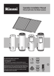
Operation / Installation Manual Commercial Solar Pre-heat Systems The collector flow and return pipes should be copper tube or alternative tube supplied by Rinnai. WARNING Plastic pipe must not be used. Plastic pipe is not suited to the high water temperatures and pressures that may occur in the collector flow and return system. NOT SUITABLE AS A POOL OR SPA HEATER 1 1540 1005 WARNING The appliance must be installed, commissioned and serviced by an authorised person in accordance with all applicable local rules and regulations. TABLE OF CONTENTS IMPORTANT INFORMATION AND WARNINGS ...................................................................................................3 Safety and Regulatory Information................................................................................................................3 Scald Hazards ...............................................................................................................................................4 Safety Devices...............................................................................................................................................5 Excessive Discharge from Safety Devices....................................................................................................5 Hydrogen Gas ...............................................................................................................................................6 Water Temperature .......................................................................................................................................6 Water Quality.................................................................................................................................................6 Draining and Filling the System.....................................................................................................................6 Maintenance and Regular Care ....................................................................................................................6 Servicing and Repair .....................................................................................................................................6 INSTALLATION AND MAINTENANCE INFORMATION .......................................................................................7 Regulations and Occupational Health and Safety (OH&S) ...........................................................................7 Location – General Information .....................................................................................................................7 Storage Cylinder Location .............................................................................................................................8 Water Pipes ...................................................................................................................................................8 Water Supply .................................................................................................................................................8 Hot Water Delivery Temperature...................................................................................................................9 Valves and Fittings ........................................................................................................................................9 INSTALLATION PROCEDURE ............................................................................................................................10 INSTALLATION OF SOLAR COLLECTORS.......................................................................................................12 Solar Collector Specifications......................................................................................................................12 System Orientation and Inclination..............................................................................................................12 Solar Collector Mounting Options................................................................................................................13 Pipe and Pump Sizing .................................................................................................................................13 Solar Collector Installation Components .....................................................................................................14 Installation – Flat Roof Frame .....................................................................................................................15 Collector Mounting Pre Assembly for a Non Framed Installation ...............................................................15 Standard Installation – Tiled Roof ...............................................................................................................16 Standard Installation – Metal Roof ..............................................................................................................17 Collector Spacing Requirements.................................................................................................................18 Flow and Return Line Layout ......................................................................................................................19 Collector Fitting Details Enduro or Equinox Collectors ...............................................................................20 Collector Fitting Details E-Frost Collectors .................................................................................................21 INSTALLATION OF STORAGE CYLINDERS......................................................................................................22 Solar Storage Cylinder Specifications .........................................................................................................22 Components Supplied with Cylinders..........................................................................................................22 Storage Cylinders Dimensions ....................................................................................................................23 INSTALLATION OF SOLAR CONTROLLER & PUMP .......................................................................................25 Components Supplied in DD Solar Control Kits ..........................................................................................25 Solar Controller............................................................................................................................................26 Solar Controller Components ......................................................................................................................26 Dipswitch Settings .......................................................................................................................................27 Location of Cold Temperature Sensors.......................................................................................................27 Resistance of Temperature Sensor LEADS................................................................................................27 INSTALLATION OF GAS BOOSTING SYSTEM .................................................................................................28 Solar Preheat with Demand Duo.................................................................................................................28 Solar Preheat with Manifold Pack ...............................................................................................................29 Solar Preheat with Demand Duo and Warm Water Valve ..........................................................................30 SAVE A SERVICE CALL ......................................................................................................................................31 Rinnai Australia Operation and Installation Manual – DD Solar Preheat 1540 1005 V1 2 IMPORTANT INFORMATION AND WARNINGS SAFETY AND REGULATORY INFORMATION DO NOT operate this system before reading the manufacturers instructions. WARNING This appliance must be installed, commissioned and serviced by an authorised person in accordance with all applicable local rules and regulations. Access covers of water heating system components will expose 240V wiring and MUST be removed by an authorised person. This appliance is not intended for use by persons (including children) with reduced physical, sensory or mental capabilities, or lack of experience and knowledge, unless they have been given supervision or instruction concerning use of the appliance by a person responsible for their safety. Children should be supervised to ensure they DO NOT play with the appliance. Any power leads from the water heater system components MUST BE plugged into an external weatherproof electrical outlet. If the power supply cord of any water heating components is damaged, it MUST BE replaced by an authorised person in order to avoid a hazard, using genuine replacement parts available from Rinnai. Take care not to touch the power plugs with wet hands. Care should be taken not to touch the pipe work as it may be HOT! The pipes between the solar collectors and storage cylinder MUST BE copper, or alternative material pipes that may be supplied by Rinnai. Plastic pipe is NOT suited to the water temperatures and pressures that may occur in the system. DO NOT place articles on or against this appliance. DO NOT store chemicals or flammable materials near this appliance. DO NOT operate with collectors or covers removed from this appliance. DO NOT activate pump unless cylinder is full of water. NEVER use a flammable spray such as hair spray, lacquer, paint, etc near this unit as this may cause a fire. NOTICE TO VICTORIAN CONSUMERS This appliance must be installed by a person licensed with the Plumbing Industry Commission. Only a licensed person will have insurance protecting their workmanship. So make sure you use a licensed person to install this appliance and ask for your Compliance Certificate. For Further information contact the Plumbing Industry Commission on 1800 015 129. Rinnai Australia Operation and Installation Manual – DD Solar Preheat 1540 1005 V1 3 IMPORTANT INFORMATION AND WARNINGS SCALD HAZARDS HOT WATER CAN CAUSE SCALDS. CHILDREN, DISABLED, ELDERLY AND THE INFIRM ARE AT THE HIGHEST RISK OF BEING SCALDED. FEEL WATER TEMPERATURE BEFORE BATHING OR SHOWERING. SCALDS FROM HOT WATER TAPS CAN RESULT IN SEVERE INJURIES TO YOUNG CHILDREN. SCALDS OCCUR WHEN CHILDREN ARE EXPOSED DIRECTLY TO HOT WATER WHEN THEY ARE PLACED INTO A BATH WHICH IS TOO HOT. ALWAYS...... Test the temperature of the water with your elbow before placing your child in the bath, also carefully feel water before bathing or showering yourself. Supervise children whenever they are in the bathroom. Make sure that the hot water tap is turned off tightly. CONSIDER..... Installing child proof tap covers or child resistant taps (both approaches will prevent a small hand being able to turn on the tap). Installing tempering valves or thermostatic mixing valves which reduce the hot water temperature delivered to the taps. Your local plumbing authority may already require that these be fitted. Contact your installer or local plumbing authority if in doubt. NEVER….. Leave a toddler in the care of another child. They may not understand the need to have the water temperature set at a safe level. Rinnai Australia Operation and Installation Manual – DD Solar Preheat 1540 1005 V1 4 IMPORTANT INFORMATION AND WARNING SAFETY DEVICES The water heating system is supplied with various safety devices including temperature sensors, overheat sensors and switches and a Pressure & Temperature Relief (PTR) valve. These devices must not be tampered with or removed. The water heating system must not be operated unless each of these devices is fitted and is in working order. DO NOT tamper with or remove safety devices. WARNINGDO NOT operate the water heater unless all safety devices are fitted and in working order. DO NOT block or seal the PTR Valve and drain pipe. Pressure & Temperature Relief (PTR) Valve This valve is located near the top of the water heater and is essential for safe operation. It is normal for the valve to release a small quantity of water through the drain line during heating. However, continuous leakage of water from the valve and its drain line may indicate a problem with the water heater. Twist cap until water flows from drain line Lift lever until water flows from drain line (Lower lever gently!) Never block the outlet of the PTR valve or it’s drain line for any reason. The easing gear must be operated at least every 6 months to remove lime deposits and verify that it is not blocked. Failure WARNINGto do this may result in the water heater failing. If the valve does not discharge water when the easing gear lever is opened, or does not seal again when the easing gear is closed, attendance by an authorised person must be arranged without delay. The PTR valve is not serviceable. EXCESSIVE DISCHARGE FROM SAFETY DEVICES Pressure & Temperature Relief (PTR) Valve It is normal and desirable that this valve allows a small quantity of water to be discharged during the heating cycle. If it discharges more than a bucket of water during a 24 hour period or discharges continuously there may be another problem. If the valve dribbles continuously, try easing the valve gear for a few seconds as described above. This may dislodge any foreign matter and alleviate the problem. If the valve discharges at high flows, especially at night, it may be as a result of the water pressure exceeding the design pressure of the water heater. Ask your installer to fit a Pressure Limiting Valve (PLV). NEVER replace the PTR valve with one which has a higher pressure rating than is specified for your water heater. WARNING Expansion Control Valve (ECV) - if fitted It is normal and desirable that this valve allows a small quantity of water to be discharged during the heating cycle. If it discharges more than a bucket of water during a 24 hour period or discharges continuously there may be another problem. If the valve leaks continuously, try easing the valve gear for a few seconds. This may dislodge any foreign matter and alleviate the problem. If this does not alleviate the problem contact Rinnai. Operate the easing gear regularly to remove any lime deposits and to verify that it is not blocked. Rinnai Australia Operation and Installation Manual – DD Solar Preheat 1540 1005 V1 5 IMPORTANT INFORMATION AND WARNING HYDROGEN GAS In the case of systems using a vitreous enamelled lined cylinder, if the hot water unit is not used for two weeks or more, a quantity of hydrogen gas, which is highly flammable, may accumulate in the water heater. To dissipate this safety, it is recommended that a non electrically operated hot tap be turned on for two minutes at a sink, basin, or bath, but not a dishwasher or other appliance. During this procedure there must be no smoking, open flame or any electrical appliance operating nearby. If hydrogen is discharged through the tap, it will probably make a sound like air escaping. WATER TEMPERATURE The solar control unit and pump ensure water circulates between the solar collectors and storage cylinder until the water at the base of the cylinder reaches approximately 65°C. Under these conditions water at the hot outlet may exceed 85°C. During periods of low solar gain supplementary heating occurs to a minimum of 60°C as required. To meet Australian regulatory requirements, supplementary heating temperature settings must be at least 60°C. WARNING WATER QUALITY The water quality of most public supplies is suitable for the water heating system. The water quality from bore wells is generally unsuitable for the water heating system. Refer to separate 'Warranty Terms and Conditions' document for water quality parameters and how they affect the warranty conditions. If in doubt about the water quality, have it checked against the parameters listed in the warranty conditions. The system is not suitable as a pool or spa heater. DRAINING AND FILLING THE SYSTEM Draining or filling normally occurs only during installation or servicing and must be carried out by an authorised person. MAINTENANCE AND REGULAR CARE Operate the easing gear of the PTR and ECV (if fitted) as described in the section ‘Safety Devices’ on page 5. SERVICING AND REPAIR Our Servicing network personnel are fully trained and equipped to give the best service on your appliance. If your appliance needs service, ring one of the service contact numbers on the back of this booklet. It is recommended that the system be serviced at least every 5 years. The pressure and temperature relief valve and expansion control valve must be checked for performance or replaced by an authorised person at intervals not exceeding 5 years or more frequently in areas where the water is classified as scaling water (refer to ‘Warranty Terms and Conditions’ document - ‘Water Quality’). It is recommended that the sacrificial anode fitted to Sunmaster Vitreous Enamel cylinders are inspected every 5 years or more frequently in areas where there is a where there is a high incidence of water deposits. This does not apply to DDS stainless steel cylinders. Anodes suited to hard and soft water are available from Rinnai. If the electric conduit, power supply cord or plug to the water heater is damaged, they must be replaced by an authorised person in order to avoid a hazard. The power supply cord and plug (if fitted) must be replaced by a genuine replacement part available from Rinnai. Rinnai Australia Operation and Installation Manual – DD Solar Preheat 1540 1005 V1 6 INSTALLATION AND MAINTENANCE INFORMATION REGULATIONS AND OCCUPATIONAL HEALTH AND SAFETY (OH&S) Installation and commissioning must be performed by authorised persons. Solar systems must be installed in accordance with these instructions and all regulatory requirements which exist in your area including those in relation to manual lifting, working at heights and on roofs. Applicable publications and regulations may include: • AS 5601 Gas Installations • AS/NZS 3500 National Plumbing and Drainage • AS/NZS 3000 Wiring rules • Building Codes of Australia (BCA) WARNING • Local Occupational Health and Safety (OH&S) regulations This appliance is not suitable for use as a domestic spa pool or swimming pool heater. Solar collectors are heavy and bulky items and are usually positioned on the roofs of buildings. Australian State and Territories have a principal Occupational Health and Safety (OH&S) Act which contains requirements relating to the handling of large, bulky or awkward items and the prevention of falls from elevated surfaces. Persons installing solar collectors must be aware of their responsibilities and be adequately trained and qualified, in accordance with local OH&S requirements. LOCATION – GENERAL INFORMATION All system components must be in an accessible location. The storage cylinder must be accessible without the use of a ladder or scaffold. Sufficient clearances shall allow access to, and removal of, all serviceable parts. Ensure the PTR valve, pump kit, and drain lines have sufficient clearances and are accessible for service and removal. The information on any data plates must also be readable. In the case of vitreous enamel lined cylinders, leave a clearance of the height of one storage cylinder above the cylinder being installed so the sacrificial anode can be inspected and replaced. This does not apply to stainless steel cylinders. Select suitable areas of roof on which to install the solar collectors as close as practicable to the cylinder. Ensure that the area is even and without cracked or damaged tiles. Collectors should be positioned for optimum solar benefit. Refer to the section 'Installation of Solar Collectors’ on page 12 for more information. The solar controller requires an AC 240V power supply. A weatherproof 240 V power point must be supplied adjacent to this. Rinnai Australia Operation and Installation Manual – DD Solar Preheat 1540 1005 V1 7 INSTALLATION AND MAINTENANCE INFORMATION STORAGE CYLINDER LOCATION The solar storage cylinders have an ingress protection rating of IPX4 making them suitable for internal or external installation. Rinnai 'external' gas boosters are suitable for external installation only. Storage cylinders must be installed in freestanding mode on a level and stable base. For external installations, storage cylinders should be mounted on a concrete base at least 50mm thick or on well seasoned, evenly spread hardwood slats with a thickness of at least 25mm. Where property damage can occur, storage cylinders should be installed with an approved safe tray (overflow tray). Ensure the cylinder does not stand on wet surfaces. WATER PIPES All hot water pipework should be insulated with sealed Polyethylene foamed or equivalent insulation to optimise performance and energy efficiency. Such insulation may also be mandatory under local regulations. With the exception of solar collector flow and return pipes, water pipe sizing should be performed in accordance with AS/NZS 3500. WATER SUPPLY The minimum and maximum water pressures for the various systems are listed on page 22. Approved pressure limiting valves may be required if the 'Maximum' rated water supply pressures are exceeded. For gas boosted systems to achieve the rated flow through the outlet of the continuous flow water heater, the minimum water supply pressures must be supplied. The systems will operate at lower pressures but the rated flow will not be achieved. Water chemistry and impurity limits are detailed in the separate Warranty document. Most metropolitan water supplies fall within these requirements. If you are unsure about water quality, contact your water authority. If sludge or foreign matter is present in the water supply, a suitable filter should be incorporated in the water supply to the storage cylinder. Rinnai Australia Operation and Installation Manual – DD Solar Preheat 1540 1005 V1 8 INSTALLATION AND MAINTENANCE INFORMATION HOT WATER DELIVERY TEMPERATURE Local regulations and/or the requirements of AS/NZS3500.4 must be considered regarding the temperature limitations of hot water supplied to areas used primarily for personal hygiene. The temperature of water to these areas is limited to 45°C for early childhood centres, primary and secondary schools and nursing homes or similar facilities for young, aged, sick or people with disabilities and 50°C for all other buildings. To comply with these requirements, a temperature limiting device, such as a thermostatic mixing or tempering valve, will be required on all solar hot water systems. VALVES AND FITTINGS The following valves and fittings are supplied with your solar hot water system: • A combined pressure and temperature (PTR) relief valve, capacity 10 kW. Relief valve pressure settings vary with models. This valve is fitted at the top of the storage cylinder. The PTR valve is a safety device and it is mandatory that it is fitted by the installer in all installations. Fittings as shown in the tables on pages 14, 22 and 25. The following valves & fittings are to be supplied by the installer: • A cold water expansion control valve (ECV). An ECV must be fitted in Western Australia and South Australia to the cold water supply to the storage cylinder to comply with local regulations. An ECV is recommended in all other geographical areas where the water supply has a tendency to cause scaling. This will reduce hot water discharge from the Pressure and Temperature Relief (PTR) valve which minimises wear on this valve. • A stop cock, non return valve and line strainer. Combination valves incorporating two or more of these functions (such as 'Trio' valves) are suitable. These are fitted to the cold water supply to the storage cylinder by the installer. • Cold water supply and hot water discharge pipework to and from the storage cylinder. • Solar collector flow and return pipes and storage cylinder connections. • An isolating valve and connection union for the gas supply to the gas booster. • An approved pressure limiting valve is required if the maximum rated water supply pressure in the table on page 22 is exceeded. Rinnai Australia Operation and Installation Manual – DD Solar Preheat 1540 1005 V1 9 INSTALLATION PROCEDURE 1. Install Solar Collectors Position and install collectors in accordance with the section “INSTALLATION OF SOLAR COLLECTORS” on page 12. 2. Position Storage Cylinders Position storage cylinders on a level base. 3. Connect PTR Valves Connect PTR valves in the location shown on the diagrams shown on pages 23 and 24. a. Leave the valve body pointing down. Tighten the valve using the spanner flats – never use the valve body. b. The PTR must be adequate for the load being applied to the storage cylinder. As any gas boosting is done after the storage cylinders the only heat input to the tank is from the solar collectors. The potential solar output for the solar collectors at PTR relief conditions is listed on page 12. Example: if each tank has 3 Enduro solar collectors, then the maximum input is 3 x 1.25 kW = 3.75 kW. This is less than the 10kW capacity of the supplied PTR valve and therefore is OK. c. Use Teflon tape on the valve. Never use hemp or other sealing materials. Ensure the tape does not protrude past the end of the thread, which could result in it blocking the water passage from the valve. 4. Connect Flow and Return Pipework Connect the flow and return pipework as shown in the diagrams on page 19, or using a suitable alternative layout that ensures the flow and return piping is balanced. 5. Connect Pump and other Pipework Connect the pump, pipework between collectors and cylinders, cold inlet, hot outlet and remaining pipework and gas boosting choice as shown in the relevant diagram on pages 28 and 30, or other suitable layout. 6. Connect the Solar Controller With power off, remove the clear cover on the solar controller. Mount the control using screws in the mounting points shown in the picture. DO not supply power to the solar controller until the system is filled with water. 7. Connect Temperature Sensor Leads Connect temperature sensor leads as shown on page 27. Ensure the leads are protected from sunlight. The sensors must be sealed in place with thermoplastic putty or silicon. It is important that these leads are installed as specified. Failure to do so will lead to malfunction or lack of hot water. 8. Fill the System Ensuring the power supply to the pump is off; turn on a hot water outlet tap(s). Remove the screw form the pump to allow air to bleed out. Open the stop cock in the cold water mains supply line. The entire system will fill with cold water. Once the pump is no longer bleeding air, replace the screw and continue to bleed the air through the taps. Air will be displaced through the tap and some air needs to be bled off using the air bleed valve on the collector near the hot sensor lead. Turn off the hot tap at the sink when water flows freely without air bubbles or air bursts. 9. Adjust Pump Speed Adjust the pump to the speed specified on page 13. 10. Check for Leaks Check all connections for leakage and tighten if necessary. This is especially important for all fittings in positions not easily accessed such as near the solar collectors. Operate the easing gear of both PTR and ECV valve at the storage cylinders to ensure these valves are functional. If leaks are detected the system must be drained and leaks repaired before the system is refilled. If this is necessary, cover the solar collectors with packaging cardboard or a tarp to prevent them from heating which could result in steam or hot water being discharged CAUTION from fittings. Rinnai Australia Operation and Installation Manual – DD Solar Preheat 1540 1005 V1 10 SYSTEM INSTALLATION 11. Adjust Dip Switches With the power OFF to the solar controller, adjust all the dip switches using the guide shown on page 27 to achieve desired frost protection. Frost protection MUST be enabled for systems using E-Frost collectors to comply with warranty conditions. IMPORTANT – Never adjust dipswitch settings with the power on. 12. Replace Cover of Solar Controller 13. Connect Power and Check Display Connect the 240 V power and observe the control display. Check that the display reflects the dipswitch settings. STARTUP - Set points e.g., “SP65” - Frost Protection State “FPon” or “FPpF” Frost Protection must be enabled when using E-Frost Collectors RUNNING STATE - The display will show the temperature of the cold sensor (in storage cylinder.). - The control then controls the circulation pump in response to the temperature differential between the solar collector and storage cylinder temperature sensors. The pump has a maximum run time of approximately 10 minutes and then it stops for approximately 8 seconds to clear any air locks. It then restarts if conditions require. - If frost protection is enabled, and the collector temperature falls below 4°C, the control will switch the pump on to circulate water through the collectors. When the collector temperature reaches 8°C the control switches the pump off. 14. Finishing the Installation Ensure that the set temperature on the gas boosting (Demand Duo or Manifold Pack) is set to 60°C or above. Ensure that the delivered temperature of the water to the building complies with all relevant regulations. Rinnai Australia Operation and Installation Manual – DD Solar Preheat 1540 1005 V1 11 INSTALLATION OF SOLAR COLLECTORS SOLAR COLLECTOR SPECIFICATIONS Enduro / Equinox (SP200A or SP200A FTC) E-Frost Flat Plate Flat Plate / Heat Pipe Copper Copper Absorber Aluminium Aluminium Casing Material Aluminium Aluminium High Performance High Performance 850 850 1940 x 1025 x 80 1940 x 1025 x 80 33 std 35 FTC 34 1.3 0.6 8 10 1.25 1.25 Type Construction Waterways Selective Surface Maximum Operating Pressure (kPa) Overall Dimensions (mm) Empty Weight (kg) Water Volume (litres) Number of risers Potential Solar Output at PTR Relief Conditions (kW) Frost Protection Std – No Frost Protection * Frost Protection to -12°C* FTC – Frost Protection to -6°C * * FOR MORE INFORMATION ON FROST PROTECTION REFER TO WARRANTYBOOKLET SYSTEM ORIENTATION AND INCLINATION The performance of any solar hot water system is determined by the way that the system is installed. In Australia, the solar collectors should face the equator (North) as shown below. Where this orientation is not practical, collectors facing within 45 degrees from North (between North-East and North-West) area acceptable, with a reduction in efficiency of approximately 5%. If the bulk of hot water consumption occurs before 2 pm face the collectors in a North - Easterly direction. If the bulk of hot water consumption occurs after 2 pm face the collectors in a North Westerly direction Rinnai Australia Operation and Installation Manual – DD Solar Preheat 1540 1005 V1 12 INSTALLATION OF SOLAR COLLECTORS The inclination of the solar collectors should ideally be the same as the latitude angle of the site. Inclinations within 20 degrees of the latitude angle of the site are acceptable, with a reduction in efficiency of approximately 5%. Latitudes of Australian Cities It is the responsibility of the installer to ensure the collector orientation and inclination comply with any local requirements. NOTE SOLAR COLLECTOR MOUNTING OPTIONS PIPE AND PUMP SIZING NOTE Ensure that the combined length of flow and return piping for each collector set is approximately the same. This will result in even flow to all collectors and optimise performance. Rinnai Australia Operation and Installation Manual – DD Solar Preheat 1540 1005 V1 13 INSTALLATION OF SOLAR COLLECTORS SOLAR COLLECTOR INSTALLATION COMPONENTS (supplied in Collector Installation kit) KIT PART NUMBERS 2 collectors – DDSP2 3 collectors – DDSP3 Number of Collectors 2 3 2 - Number of Collectors 2 3 2 2 Mounting Rail Medium 14201197 Stop End - (1 x plug ¾G (Kinco) + 1 x ¾ Kinco nut and olive) 2 Mounting Rail Large 4 (Not used with E-Frost Collector) 14201198 28801025 6 2 Collector Mounting Strap (supplied with collectors) 4 12401012 Compression Union ¾ - ¾ (1 x Nipple G¾ (Kinco) + 2 x ¾ Kinco nut and olive) (Half of these not used with E-Frost Collector) 4 4 M8 Bolt, Washer and Nut BOLT (used to bolt collector mounting WASHER strap to mounting rail) NUT 22601052 17401072 16801062 2 8 32201709 2 12 Compression Union ¾ - ½ Collector Retainer (1 x Nipple G¾ (Kinco) + 1 x ¾ Kinco nut and olive 33201711 + 1x ½ Kinco nut and olive ) 26601706 1 8 1 12 BOLT 22601073 M6 Bolt, Washer and Nut WASHER 17401073 (used with collector retainers) NUT 1 16801007 Rinnai Australia Operation and Installation Manual – DD Solar Preheat Kinco Nut ½ 16801012 Kinco Olive ½ 33001012 1 1540 1005 V1 14 INSTALLATION OF SOLAR COLLECTORS INSTALLATION – FLAT ROOF FRAME • Assemble and install the frame as described in “Installation Manual for Roof Frames for use with Rinnai Solar Hot Water Systems” COLLECTOR MOUNTING PRE ASSEMBLY FOR A NON FRAMED INSTALLATION • Assemble the collector rail components as shown in the diagram below. • Only loosely attach the collector retainers to the rails. Rinnai Australia Operation and Installation Manual – DD Solar Preheat 1540 1005 V1 15 INSTALLATION OF SOLAR COLLECTORS STANDARD INSTALLATION – TILED ROOF • Position the lower collector mounting rail assembly. • For aesthetic reasons it is best to mount as close as possible to the gutter. • Attach the collector mounting straps to the rafter or truss under the tiles • Place the collector(s) onto the roof above the lower rail. • If more than one collector is being installed then join them together using the compression fittings supplied. • Push down on the collector retainers to clamp the collector and tighten nuts. • Position the upper collector rail above the collectors. Push down on the retainers to clamp the collector and tighten the nuts. • Attach the collector mounting straps to the rafter or truss under the tiles. • Replace the tiles and ensure the collector is secure. Rinnai Australia Operation and Installation Manual – DD Solar Preheat 1540 1005 V1 16 INSTALLATION OF SOLAR COLLECTORS STANDARD INSTALLATION – METAL ROOF • Position the lower collector mounting rail assembly so that the rail is over the roof purlin. For aesthetic reason it is best to mount as close as possible to the gutter. • Drill through the roof iron and purlin using the holes in the rail as a guide. Apply some silicone sealant down the holes to ensure no water leakage. • Bolt the rail to the roof purlin using a suitable fastener • Position the collector(s) onto the roof above the lower rail. If more than one collector is being installed, join them together using the compression fittings supplied. • Push down on the collector retainers to clamp the collector and tighten the nuts • Place the upper collector mounting rail above the collectors. Push down on the collector retainers to clamp the collector and tighten the nuts. • Drill through the roof iron and purlin using the upper mounting rail as a guide. Apply some silicone sealant down the holes to ensure no water leakage and secure with suitable. Alternatively the rail can be attached to the roof using the collector mounting straps. Rinnai Australia Operation and Installation Manual – DD Solar Preheat 1540 1005 V1 17 INSTALLATION OF SOLAR COLLECTORS COLLECTOR SPACING REQUIREMENTS Rinnai Australia Operation and Installation Manual – DD Solar Preheat 1540 1005 V1 18 INSTALLATION OF SOLAR COLLECTORS FLOW AND RETURN LINE LAYOUT ENDURO AND EQUINOX COLLECTORS E-FROST COLLECTORS Rinnai Australia Operation and Installation Manual – DD Solar Preheat 1540 1005 V1 19 INSTALLATION OF SOLAR COLLECTORS COLLECTOR FITTING DETAILS ENDURO OR EQUINOX COLLECTORS Rinnai Australia Operation and Installation Manual – DD Solar Preheat 1540 1005 V1 20 INSTALLATION OF SOLAR COLLECTORS COLLECTOR FITTING DETAILS E-FROST COLLECTORS Rinnai Australia Operation and Installation Manual – DD Solar Preheat 1540 1005 V1 21 INSTALLATION OF STORAGE CYLINDERS SOLAR STORAGE CYLINDER SPECIFICATIONS All Storage Cylinders PTR setting (kPa) 850 Rating of PTR valve (kW) 10 Expansion Control Valve (ECV) Setting (kPa) Supplied by installer if required 700 Max supply pressure with ECV (kPa) 550 Max supply pressure without ECV (kPa) 680 Pressure Limiting Valve (kPa) Supplied by installer if required 500 COMPONENTS SUPPLIED WITH CYLINDERS Items Supplied with Sunmaster (Vitreous Enamel) Cylinder 1 Items Supplied with DDS (Stainless Steel) Cylinder (DDSTK) 1 PTR Valve 1 92501192 PTR Valve 11004784 Adaptor ¾ R to ½ Rp 19801004 Nipple R 15 mm 17201021 ½ Kinco Olive 33001012 ½ Kinco Nut 16801012 1 Adaptor R ¾ x Rp ½ 3 1 Adaptor R ¾ x Rp ¾ 1 1 Rinnai Australia Operation and Installation Manual – DD Solar Preheat 1540 1005 V1 22 INSTALLATION OF STORAGE CYLINDERS STORAGE CYLINDERS DIMENSIONS Sunmaster – Vitreous Enamel Cylinders SG270 SG340 Cylinder Height (mm) 1265 1510 PTR / Hot Water Outlet (mm) 985 1200 Solar Return (mm) 700 700 Cold Water Inlet (mm) 260 260 Diameter (mm) 685 685 Weight Empty (kg) 95 103 All connections: ¾ Rp Rinnai Australia Operation and Installation Manual – DD Solar Preheat 1540 1005 V1 23 INSTALLATION OF STORAGE CYLINDERS DDS - Stainless Steel Cylinders DDS250 DDS315 Cylinder Height (mm) 1690 2080 PTR / Hot Water Outlet (mm) 1464 1854 Weight Empty (kg) 56 68 Solar Return and PTR connections: ¾ Rp Hot and Cold Inlet connections:1 ¼ Rp Rinnai Australia Operation and Installation Manual – DD Solar Preheat 1540 1005 V1 24 INSTALLATION OF SOLAR CONTROLLER & PUMP - DDSCP25 DDSCP25 1 DDSCP20 DDSCP20 COMPONENTS SUPPLIED IN DD SOLAR CONTROL KITS - 1 Control Box and Pump Assembly Control Box and Pump Assembly Includes USP25-80N pump, DDSC solar controller, power lead, hot and cold temperature sensor leads 39001733 Includes USP20-60N pump, DDSC solar controller, power lead, hot and cold temperature sensor leads 39001732 1 - Pump – Grundfos 20-60N* 1 1 - 1 1 1 1 1 Union Valve Set 25 mm* 1 Hot Sensor Lead (20 m)* 1 Hot Sensor Sheath 10204714 Air Bleed Valve 11007701 1 1 1 Adaptor R ¾ x Rp ½ 19801004 ¾ Kinco Olive 33001011 ¾ Kinco Nut 16801018 31002706 1 Cold Sensor Lead (2 m)* 1 16601080 1 39001729 1 1 31002710 Temperature Sensor Sheath 125 mm 10204719 1¼ nipple 17201046 T 1¼ Rp 19001021 T ¾ Rp 19001011 G3/4 (Comp) x R 1 union 33201730 1 1 1 1 1 1 1 Adaptor 32 to ¾ 3 1 16601085 1 Demand Duo Solar Controller* 1 Pump – Grundfos 25-80N* DDUPS2580N DDUPS2060N Union Valve Set 20 mm* 1 17201047 1 G3/4 (Comp) x R ¾ union 1 33201713 2 * Part of Pump and Controller Assembly but shown separately for clarity Rinnai Australia Operation and Installation Manual – DD Solar Preheat 1540 1005 V1 25 INSTALLATION OF SOLAR CONTROLLER SOLAR CONTROLLER The solar controller’s function is to turn the solar pump on and off to enable the solar collectors to transfer heated water to the storage cylinder when there is capacity in the cylinder to store more energy and when the temperature difference between the cylinder and collector temperatures is suitable for energy collection A differential temperature between solar collector (hot sensor) and tank (cold sensor) of greater than 9°C pump causes the pump to be switched on. When differential falls to below 5°C the pump switches off. When the cold temperature sensor reaches 65° the pump is switched off. This prevent water that is too hot returning from the solar collectors to the storage cylinder and activating the P&TR valve. The other function of the controller is to pump water through the collectors when there are frost conditions to prevent the collector from freezing. When the hot temperature sensor (in collector) drops below 4°C the pump activates to prevent freezing. When this temperature reaches 8°C the pump stops. This is an option is selected using the dipswitches. This function must be enabled for systems using E-Frost collectors to comply with warranty conditions. COLD COLD EMPTY HOT DIP Switches settings on next page HOT Display Shows tank temperature EMPTY SOLAR CONTROLLER COMPONENTS Mounting Points (x4) 240 V Power Power to Pump Max Rating 1 kW Rinnai Australia Operation and Installation Manual – DD Solar Preheat Temperature Sensor Leads for resistance values see next page 1540 1005 V1 26 INSTALLATION OF SOLAR CONTROLLER DIPSWITCH SETTINGS Frost Protection Not Enabled Must be in OFF position Frost Protection Enabled Must be in OFF position Must be in OFF position Frost Protection Frost Protection Must be in OFF position Legend: black indicates position of switch Note: Dipswitches are upside down in controller as shown above LOCATION OF COLD TEMPERATURE SENSORS Stainless Steel Storage Cylinder Vitreous Enamel Storage Cylinder RESISTANCE OF TEMPERATURE SENSOR LEADS Both temperature sensor leads have approximately the following resistances. This information can be used to verify performance of the leads. Temperature (°C) Resistance (Ohms) 0 32000 10 19000 20 12000 30 8000 40 5000 50 3000 60 2000 70 1100 80 1000 90 900 100 700 Rinnai Australia Operation and Installation Manual – DD Solar Preheat 1540 1005 V1 27 INSTALLATION OF GAS BOOSTING SYSTEM The installation of the Manifold Pack or Demand Duo must be carried out in accordance with instructions supplied with the system. Piping connections to the Solar Preheat must be carried out as shown on the following pages. The temperature setting of the gas boosters must be set to at least 60°C to comply with plumbing regulations SOLAR PREHEAT WITH DEMAND DUO Rinnai Australia Operation and Installation Manual – DD Solar Preheat 1540 1005 V1 28 INSTALLATION OF GAS BOOSTING SYSTEM SOLAR PREHEAT WITH MANIFOLD PACK Rinnai Australia Operation and Installation Manual – DD Solar Preheat 1540 1005 V1 29 INSTALLATION OF GAS BOOSTING SYSTEM SOLAR PREHEAT WITH DEMAND DUO AND WARM WATER VALVE UV not shown with Warm Water Valve in above picture. Refer to the instructions provided with the Warm Water Valve for details. Rinnai Australia Operation and Installation Manual – DD Solar Preheat 1540 1005 V1 30 SAVE A SERVICE CALL Problem Cause Remedy Booster heating not operating Check to ensure the power supply to the gas booster system is 'ON'. Check gas is available and turned ON'. Close the hot tap and wait for 10 seconds and open it again. The hot tap must be opened enough to ensure that the flow rate is sufficient to cause the gas booster(s) to light. Check the isolation valve in the gas line is opened. If there is gas supply to other appliances in the building, try lighting another gas appliance. Refer to your plumber to ensure the gas line has been purged of air after installation. Refer to the manual supplied with your boosting system for more information Insufficient or no hot water OR Insufficient gas supply for gas boosted heating system Excessive hot water consumption Insufficient flow may occur if more outlets are in use at the same time than the system was designed for. and exceed the rated flow capacity of the gas booster. Have a plumber install water saving fixtures and/or flow control or pressure limiting valves to reduce consumption. Gas Booster Setting The delivery temperature of the gas boosting system is normally 65°C. If the temperatures are higher than this, the flow of water through the gas booster will reduce and may result in insufficient flow rate. Ensure the boosting system is set for the temperature the system was designed for. PTR / Expansion Control valve discharging water continuously Never replace the PTR valve with one which has a higher pressure rating than is specified for your water heater. If the valve discharges hot water at high flows, (dumps) there may be a serious problem. Switch off the power supply to the Solar Controller and contact Rinnai. Restriction in the hot tap or failure of the cold water supply to the water heater. Insufficient Sunlight Collectors shaded Reduced sunlight due to overcast weather in summer or low solar contribution in winter will result in an increased dependence on gas boosting. Higher gas use bills under these conditions, especially in winter, are normal. Ensure the trees or other objects are not shading onto the collector surface (Trim the trees or relocate the solar collector if the obstruction is permanent). Make sure the glass on the collector is not dirty. Check that positioning and alignment of solar collectors is in accordance with the section 'Location and alignment of solar collectors'. Make sure the glass on the collector is not dirty. Little or no water circulation in the solar 'flow and return' loop There are numerous causes of little or no circulation in the solar 'flow and return circuit the circulation of water through the collectors. These causes must be investigated by a qualified person. Contact Rinnai. Water flow fluctuations OR Solar System not operating Check for water flow at the other taps and that the cold water isolation is fully open. High hot water usage Higher than normal number of hot taps in use at the same time may cause a decrease in the hot water flow from the taps. Water Hammer Gas Booster operating too frequently No water from the hot tap WARNING It is normal and desirable that these valves allow a small quantity of water to be discharged during the heating cycle. If more than a bucket of water is discharged from an individual cylinder during a 24 hour period or the valve discharges continuously there may be another problem. If the valve dribbles continuously, try easing the valve gear for a few seconds as described under 'Regular Care'. This may dislodge any foreign matter and alleviate the problem. If the valve discharges at high flows, especially at night, it may be as a result of the water pressure exceeding the design pressure of the water heater. Ask your installer to fit a Pressure Limiting Valve (PLV). System plumbing Have a plumber check clipping of hot and cold water pipework and install a pressure limiting valve and water hammer arrestor as required. Rinnai Australia Operation and Installation Manual – DD Solar Preheat 1540 1005 V1 31 1540 1005 Rinnai Australia Operation and Installation Manual – DD Solar Preheat 1540 1005 V1 32


