1
SERVICE MANUAL
HS Series Slicer
HS6
HS6N
HS7
HS7N
HS8
HS8N
HS9
HS9N
ML-136244
ML-136245
ML-136248
ML-136249
ML-136250
ML-136251
ML-136252
ML-136253
- NOTICE This Manual is prepared for the use of trained Hobart Service
Technicians and should not be used by those not properly
qualified.
This manual is not intended to be all encompassing. If you have
not attended a Hobart Service School for this product, you should
read, in its entirety, the repair procedure you wish to perform to
determine if you have the necessary tools, instruments and skills
required to perform the procedure. Procedures for which you do
not have the necessary tools, instruments and skills should be
performed by a trained Hobart Service Technician.
The reproduction, transfer, sale or other use of this Manual,
without the express written consent of Hobart, is prohibited.
This manual has been provided to you by ITW Food Equipment
Group LLC ("ITW FEG") without charge and remains the property
of ITW FEG, and by accepting this manual you agree that you will
return it to ITW FEG promptly upon its request for such return at
any time in the future.
A product of Hobart Service
701 S. Ridge Ave Troy, OH 45374
F45476 Rev. A (0313)
HS Series Slicer
TABLE OF CONTENTS
GENERAL . . . . . . . . . . . . . . . . . . . . . . . . . . . . . . . . . . . . . . . . . . . . . . . . . . . . . . . . . . . . . . . . . . . . . . . . . . . . . . . . . . . . . . . . . . . . . . . . . .
INTRODUCTION . . . . . . . . . . . . . . . . . . . . . . . . . . . . . . . . . . . . . . . . . . . . . . . . . . . . . . . . . . . . . . . . . . . . . . . . . . . . . . . . . . . . . . .
HOME POSITION . . . . . . . . . . . . . . . . . . . . . . . . . . . . . . . . . . . . . . . . . . . . . . . . . . . . . . . . . . . . . . . . . . . . . . . . . . . . . . . . . .
MODELS . . . . . . . . . . . . . . . . . . . . . . . . . . . . . . . . . . . . . . . . . . . . . . . . . . . . . . . . . . . . . . . . . . . . . . . . . . . . . . . . . . . . . . . . . . .
FEATURES . . . . . . . . . . . . . . . . . . . . . . . . . . . . . . . . . . . . . . . . . . . . . . . . . . . . . . . . . . . . . . . . . . . . . . . . . . . . . . . . . . . . . . . .
ELECTRICAL COMPONENTS . . . . . . . . . . . . . . . . . . . . . . . . . . . . . . . . . . . . . . . . . . . . . . . . . . . . . . . . . . . . . . . . . . . . . .
SPECIFICATIONS . . . . . . . . . . . . . . . . . . . . . . . . . . . . . . . . . . . . . . . . . . . . . . . . . . . . . . . . . . . . . . . . . . . . . . . . . . . . . . . . . . . . . .
ELECTRICAL . . . . . . . . . . . . . . . . . . . . . . . . . . . . . . . . . . . . . . . . . . . . . . . . . . . . . . . . . . . . . . . . . . . . . . . . . . . . . . . . . . . . . .
MOTOR . . . . . . . . . . . . . . . . . . . . . . . . . . . . . . . . . . . . . . . . . . . . . . . . . . . . . . . . . . . . . . . . . . . . . . . . . . . . . . . . . . . . . . . . . . . .
CORD AND PLUG . . . . . . . . . . . . . . . . . . . . . . . . . . . . . . . . . . . . . . . . . . . . . . . . . . . . . . . . . . . . . . . . . . . . . . . . . . . . . . . . . .
THICKNESS . . . . . . . . . . . . . . . . . . . . . . . . . . . . . . . . . . . . . . . . . . . . . . . . . . . . . . . . . . . . . . . . . . . . . . . . . . . . . . . . . . . . . . .
CARRIAGE TRAVEL . . . . . . . . . . . . . . . . . . . . . . . . . . . . . . . . . . . . . . . . . . . . . . . . . . . . . . . . . . . . . . . . . . . . . . . . . . . . . . .
STROKE COUNT . . . . . . . . . . . . . . . . . . . . . . . . . . . . . . . . . . . . . . . . . . . . . . . . . . . . . . . . . . . . . . . . . . . . . . . . . . . . . . . . . . .
KNIFE SPEED . . . . . . . . . . . . . . . . . . . . . . . . . . . . . . . . . . . . . . . . . . . . . . . . . . . . . . . . . . . . . . . . . . . . . . . . . . . . . . . . . . . . .
KNIFE DIMENSION . . . . . . . . . . . . . . . . . . . . . . . . . . . . . . . . . . . . . . . . . . . . . . . . . . . . . . . . . . . . . . . . . . . . . . . . . . . . . . . .
KNIFE SHARPENER . . . . . . . . . . . . . . . . . . . . . . . . . . . . . . . . . . . . . . . . . . . . . . . . . . . . . . . . . . . . . . . . . . . . . . . . . . . . . . .
WEIGHT . . . . . . . . . . . . . . . . . . . . . . . . . . . . . . . . . . . . . . . . . . . . . . . . . . . . . . . . . . . . . . . . . . . . . . . . . . . . . . . . . . . . . . . . . . .
LUBRICATION . . . . . . . . . . . . . . . . . . . . . . . . . . . . . . . . . . . . . . . . . . . . . . . . . . . . . . . . . . . . . . . . . . . . . . . . . . . . . . . . . . . . . . . . .
TOOLS . . . . . . . . . . . . . . . . . . . . . . . . . . . . . . . . . . . . . . . . . . . . . . . . . . . . . . . . . . . . . . . . . . . . . . . . . . . . . . . . . . . . . . . . . . . . . . . . .
6
6
6
6
6
6
6
6
6
6
6
6
7
7
7
7
7
7
7
REMOVAL AND REPLACEMENT PARTS . . . . . . . . . . . . . . . . . . . . . . . . . . . . . . . . . . . . . . . . . . . . . . . . . . . . . . . . . . . . . . . . . . . 9
SHARPENER . . . . . . . . . . . . . . . . . . . . . . . . . . . . . . . . . . . . . . . . . . . . . . . . . . . . . . . . . . . . . . . . . . . . . . . . . . . . . . . . . . . . . . . . . . 9
SHARPENER - REMOVAL . . . . . . . . . . . . . . . . . . . . . . . . . . . . . . . . . . . . . . . . . . . . . . . . . . . . . . . . . . . . . . . . . . . . . . . . . . 9
SHARPENER - DISASSEMBLY . . . . . . . . . . . . . . . . . . . . . . . . . . . . . . . . . . . . . . . . . . . . . . . . . . . . . . . . . . . . . . . . . . . . . 9
TOP KNIFE COVER . . . . . . . . . . . . . . . . . . . . . . . . . . . . . . . . . . . . . . . . . . . . . . . . . . . . . . . . . . . . . . . . . . . . . . . . . . . . . . . . . . . 10
TOP KNIFE COVER - REMOVAL . . . . . . . . . . . . . . . . . . . . . . . . . . . . . . . . . . . . . . . . . . . . . . . . . . . . . . . . . . . . . . . . . . 10
TOP KNIFE COVER - REPLACEMENT . . . . . . . . . . . . . . . . . . . . . . . . . . . . . . . . . . . . . . . . . . . . . . . . . . . . . . . . . . . . 10
RING GUARD . . . . . . . . . . . . . . . . . . . . . . . . . . . . . . . . . . . . . . . . . . . . . . . . . . . . . . . . . . . . . . . . . . . . . . . . . . . . . . . . . . . . . . . . . 11
RING GUARD - REMOVAL . . . . . . . . . . . . . . . . . . . . . . . . . . . . . . . . . . . . . . . . . . . . . . . . . . . . . . . . . . . . . . . . . . . . . . . . 11
RING GUARD - REPLACEMENT . . . . . . . . . . . . . . . . . . . . . . . . . . . . . . . . . . . . . . . . . . . . . . . . . . . . . . . . . . . . . . . . . . 11
KNIFE EDGE PROTECTOR LOCK - REMOVAL & REPLACEMENT . . . . . . . . . . . . . . . . . . . . . . . . . . . . . . . . 11
DEFLECTOR . . . . . . . . . . . . . . . . . . . . . . . . . . . . . . . . . . . . . . . . . . . . . . . . . . . . . . . . . . . . . . . . . . . . . . . . . . . . . . . . . . . . . . . . . 12
CARRIAGE TRAY AND MEAT GRIP ASSEMBLY . . . . . . . . . . . . . . . . . . . . . . . . . . . . . . . . . . . . . . . . . . . . . . . . . . . . . . 12
CARRIAGE TRAY ASSEMBLY - REMOVAL . . . . . . . . . . . . . . . . . . . . . . . . . . . . . . . . . . . . . . . . . . . . . . . . . . . . . . . 12
CARRIAGE TRAY - DISASSEMBLY . . . . . . . . . . . . . . . . . . . . . . . . . . . . . . . . . . . . . . . . . . . . . . . . . . . . . . . . . . . . . . . 12
MEAT GRIP - DISASSEMBLY . . . . . . . . . . . . . . . . . . . . . . . . . . . . . . . . . . . . . . . . . . . . . . . . . . . . . . . . . . . . . . . . . . . . . 13
CARRIAGE TRAY SUPPORT ARM ASSEMBLY - DISASSEMBLY . . . . . . . . . . . . . . . . . . . . . . . . . . . . . . . . . . 13
KNIFE- REMOVABLE (NON N - MODEL SLICER) . . . . . . . . . . . . . . . . . . . . . . . . . . . . . . . . . . . . . . . . . . . . . . . . . . . . . 14
KNIFE - REMOVAL . . . . . . . . . . . . . . . . . . . . . . . . . . . . . . . . . . . . . . . . . . . . . . . . . . . . . . . . . . . . . . . . . . . . . . . . . . . . . . . . 14
KNIFE - REPLACEMENT . . . . . . . . . . . . . . . . . . . . . . . . . . . . . . . . . . . . . . . . . . . . . . . . . . . . . . . . . . . . . . . . . . . . . . . . . . 14
KNIFE REPLACEMENT (KNIFE REMOVAL TOOL UNAVAILABLE) . . . . . . . . . . . . . . . . . . . . . . . . . . . . . . . . . 15
KNIFE - NON REMOVABLE (N - MODEL SLICER) . . . . . . . . . . . . . . . . . . . . . . . . . . . . . . . . . . . . . . . . . . . . . . . . . . . . . 17
GAUGE PLATE ASSEMBLY . . . . . . . . . . . . . . . . . . . . . . . . . . . . . . . . . . . . . . . . . . . . . . . . . . . . . . . . . . . . . . . . . . . . . . . . . . . 17
LIFT ASSIST LEVER (HS7 & HS9) . . . . . . . . . . . . . . . . . . . . . . . . . . . . . . . . . . . . . . . . . . . . . . . . . . . . . . . . . . . . . . . . . . . . 18
LIFT LEG ASSEMBLY (HS6 & HS8) . . . . . . . . . . . . . . . . . . . . . . . . . . . . . . . . . . . . . . . . . . . . . . . . . . . . . . . . . . . . . . . . . . . 18
BOTTOM COVER . . . . . . . . . . . . . . . . . . . . . . . . . . . . . . . . . . . . . . . . . . . . . . . . . . . . . . . . . . . . . . . . . . . . . . . . . . . . . . . . . . . . . 19
AUTO / MANUAL ROD ASSEMBLY (HS7 & HS9) . . . . . . . . . . . . . . . . . . . . . . . . . . . . . . . . . . . . . . . . . . . . . . . . . . . . . . 19
AUTO / MANUAL ROD - REMOVAL . . . . . . . . . . . . . . . . . . . . . . . . . . . . . . . . . . . . . . . . . . . . . . . . . . . . . . . . . . . . . . . 19
AUTO / MANUAL ROD - DISASSEMBLY . . . . . . . . . . . . . . . . . . . . . . . . . . . . . . . . . . . . . . . . . . . . . . . . . . . . . . . . . . 20
AUTO DRIVE MECHANISM (HS7 & HS9) . . . . . . . . . . . . . . . . . . . . . . . . . . . . . . . . . . . . . . . . . . . . . . . . . . . . . . . . . . . . . . 20
AUTO DRIVE MECHANISM - REMOVAL . . . . . . . . . . . . . . . . . . . . . . . . . . . . . . . . . . . . . . . . . . . . . . . . . . . . . . . . . . 20
AUTO DRIVE MECHANISM - DISASSEMBLY . . . . . . . . . . . . . . . . . . . . . . . . . . . . . . . . . . . . . . . . . . . . . . . . . . . . . . 21
AUTO DRIVE MECHANISM - REPLACEMENT . . . . . . . . . . . . . . . . . . . . . . . . . . . . . . . . . . . . . . . . . . . . . . . . . . . . . 21
ROLLER BEARING . . . . . . . . . . . . . . . . . . . . . . . . . . . . . . . . . . . . . . . . . . . . . . . . . . . . . . . . . . . . . . . . . . . . . . . . . . . . . . . . . . . 22
TRANSPORT & SLIDE ROD . . . . . . . . . . . . . . . . . . . . . . . . . . . . . . . . . . . . . . . . . . . . . . . . . . . . . . . . . . . . . . . . . . . . . . . . . . . 22
REMOVAL . . . . . . . . . . . . . . . . . . . . . . . . . . . . . . . . . . . . . . . . . . . . . . . . . . . . . . . . . . . . . . . . . . . . . . . . . . . . . . . . . . . . . . . . 22
TRANSPORT - DISASSEMBLY . . . . . . . . . . . . . . . . . . . . . . . . . . . . . . . . . . . . . . . . . . . . . . . . . . . . . . . . . . . . . . . . . . . . 23
F45476 Rev. A (0313)
Page 2 of 85
HS Series Slicer
KNIFE MOTOR AND BRACKET ASSEMBLY . . . . . . . . . . . . . . . . . . . . . . . . . . . . . . . . . . . . . . . . . . . . . . . . . . . . . . . . . .
KNIFE MOTOR AND BRACKET - REMOVAL . . . . . . . . . . . . . . . . . . . . . . . . . . . . . . . . . . . . . . . . . . . . . . . . . . . . . .
KNIFE MOTOR AND BRACKET - REPLACEMENT . . . . . . . . . . . . . . . . . . . . . . . . . . . . . . . . . . . . . . . . . . . . . . . .
CAPACITOR . . . . . . . . . . . . . . . . . . . . . . . . . . . . . . . . . . . . . . . . . . . . . . . . . . . . . . . . . . . . . . . . . . . . . . . . . . . . . . . . . . . . . . . . . .
CAPACITOR - REMOVAL . . . . . . . . . . . . . . . . . . . . . . . . . . . . . . . . . . . . . . . . . . . . . . . . . . . . . . . . . . . . . . . . . . . . . . . . .
CAPACITOR - REPLACEMENT . . . . . . . . . . . . . . . . . . . . . . . . . . . . . . . . . . . . . . . . . . . . . . . . . . . . . . . . . . . . . . . . . . .
ELECTRONIC START SWITCH . . . . . . . . . . . . . . . . . . . . . . . . . . . . . . . . . . . . . . . . . . . . . . . . . . . . . . . . . . . . . . . . . . . . . . .
KNIFE SHAFT . . . . . . . . . . . . . . . . . . . . . . . . . . . . . . . . . . . . . . . . . . . . . . . . . . . . . . . . . . . . . . . . . . . . . . . . . . . . . . . . . . . . . . . .
KNIFE SHAFT - REMOVAL . . . . . . . . . . . . . . . . . . . . . . . . . . . . . . . . . . . . . . . . . . . . . . . . . . . . . . . . . . . . . . . . . . . . . . . .
KNIFE SHAFT - REPLACEMENT . . . . . . . . . . . . . . . . . . . . . . . . . . . . . . . . . . . . . . . . . . . . . . . . . . . . . . . . . . . . . . . . . .
SHARPENER HOUSING MOUNT . . . . . . . . . . . . . . . . . . . . . . . . . . . . . . . . . . . . . . . . . . . . . . . . . . . . . . . . . . . . . . . . . . . . .
SHARPENER HOUSING MOUNT - REMOVAL . . . . . . . . . . . . . . . . . . . . . . . . . . . . . . . . . . . . . . . . . . . . . . . . . . . . .
KNIFE EDGE PROTECTOR . . . . . . . . . . . . . . . . . . . . . . . . . . . . . . . . . . . . . . . . . . . . . . . . . . . . . . . . . . . . . . . . . . . . . . .
SHARPENER HOUSING MOUNT - INSTALLATION . . . . . . . . . . . . . . . . . . . . . . . . . . . . . . . . . . . . . . . . . . . . . . . .
INDEX SLIDE MECHANISM . . . . . . . . . . . . . . . . . . . . . . . . . . . . . . . . . . . . . . . . . . . . . . . . . . . . . . . . . . . . . . . . . . . . . . . . . . .
INDEX SLIDE MECHANISM - REMOVAL . . . . . . . . . . . . . . . . . . . . . . . . . . . . . . . . . . . . . . . . . . . . . . . . . . . . . . . . . .
INDEX SLIDE MECHANISM - DISASSEMBLY . . . . . . . . . . . . . . . . . . . . . . . . . . . . . . . . . . . . . . . . . . . . . . . . . . . . .
INDEX SLIDE MECHANISM - REASSEMBLY . . . . . . . . . . . . . . . . . . . . . . . . . . . . . . . . . . . . . . . . . . . . . . . . . . . . . .
INDEXING CAM . . . . . . . . . . . . . . . . . . . . . . . . . . . . . . . . . . . . . . . . . . . . . . . . . . . . . . . . . . . . . . . . . . . . . . . . . . . . . . . . . . . . . . .
CONTROL BOARD & KEYPAD (HS6 & HS8) . . . . . . . . . . . . . . . . . . . . . . . . . . . . . . . . . . . . . . . . . . . . . . . . . . . . . . . . . .
CONTROL BOARD (HS7 & HS9) . . . . . . . . . . . . . . . . . . . . . . . . . . . . . . . . . . . . . . . . . . . . . . . . . . . . . . . . . . . . . . . . . . . . . .
CONTROL BOARD - REMOVAL . . . . . . . . . . . . . . . . . . . . . . . . . . . . . . . . . . . . . . . . . . . . . . . . . . . . . . . . . . . . . . . . . . .
CONTROL BOARD - REPLACEMENT . . . . . . . . . . . . . . . . . . . . . . . . . . . . . . . . . . . . . . . . . . . . . . . . . . . . . . . . . . . . .
KEYPAD (HS7 & HS9) . . . . . . . . . . . . . . . . . . . . . . . . . . . . . . . . . . . . . . . . . . . . . . . . . . . . . . . . . . . . . . . . . . . . . . . . . . . . . . . .
KEYPAD BOARD - REMOVAL . . . . . . . . . . . . . . . . . . . . . . . . . . . . . . . . . . . . . . . . . . . . . . . . . . . . . . . . . . . . . . . . . . . . .
KEYPAD HOUSING - REPLACEMENT . . . . . . . . . . . . . . . . . . . . . . . . . . . . . . . . . . . . . . . . . . . . . . . . . . . . . . . . . . . .
GAUGE PLATE CLOSED TO STOP SWITCH 2S (HS8 & HS9) . . . . . . . . . . . . . . . . . . . . . . . . . . . . . . . . . . . . . . . . .
CARRIAGE TRAY INTERLOCK SWITCH 1S (HS8 & HS9) . . . . . . . . . . . . . . . . . . . . . . . . . . . . . . . . . . . . . . . . . . . . .
AUTO / MANUAL SWITCH 5S (HS7 & HS9) . . . . . . . . . . . . . . . . . . . . . . . . . . . . . . . . . . . . . . . . . . . . . . . . . . . . . . . . . . .
CARRIAGE HOME SWITCH 3S ( HS7, HS8 & HS9) . . . . . . . . . . . . . . . . . . . . . . . . . . . . . . . . . . . . . . . . . . . . . . . . . . . .
KNIFE RESET SWITCH 4S (HS8 & HS9) . . . . . . . . . . . . . . . . . . . . . . . . . . . . . . . . . . . . . . . . . . . . . . . . . . . . . . . . . . . . . .
POLY-V BELT . . . . . . . . . . . . . . . . . . . . . . . . . . . . . . . . . . . . . . . . . . . . . . . . . . . . . . . . . . . . . . . . . . . . . . . . . . . . . . . . . . . . . . . . .
POLY-V BELT - REMOVAL . . . . . . . . . . . . . . . . . . . . . . . . . . . . . . . . . . . . . . . . . . . . . . . . . . . . . . . . . . . . . . . . . . . . . . . .
POLY-V BELT - REPLACEMENT . . . . . . . . . . . . . . . . . . . . . . . . . . . . . . . . . . . . . . . . . . . . . . . . . . . . . . . . . . . . . . . . . .
23
23
24
24
24
24
24
25
25
25
26
26
27
27
28
28
29
29
30
30
31
31
31
32
32
32
33
34
34
34
35
36
36
36
SERVICE PROCEDURES AND ADJUSTMENTS . . . . . . . . . . . . . . . . . . . . . . . . . . . . . . . . . . . . . . . . . . . . . . . . . . . . . . . . . . .
GASKET INSPECTION . . . . . . . . . . . . . . . . . . . . . . . . . . . . . . . . . . . . . . . . . . . . . . . . . . . . . . . . . . . . . . . . . . . . . . . . . . . . . . . .
TOP KNIFE COVER CHECK/ ADJUSTMENT . . . . . . . . . . . . . . . . . . . . . . . . . . . . . . . . . . . . . . . . . . . . . . . . . . . . . . . . . .
TOP KNIFE COVER - CHECK . . . . . . . . . . . . . . . . . . . . . . . . . . . . . . . . . . . . . . . . . . . . . . . . . . . . . . . . . . . . . . . . . . . . .
TOP KNIFE COVER - ADJUSTMENT . . . . . . . . . . . . . . . . . . . . . . . . . . . . . . . . . . . . . . . . . . . . . . . . . . . . . . . . . . . . . .
RING GUARD ADJUSTMENT . . . . . . . . . . . . . . . . . . . . . . . . . . . . . . . . . . . . . . . . . . . . . . . . . . . . . . . . . . . . . . . . . . . . . . . . .
RING GUARD - CHECK . . . . . . . . . . . . . . . . . . . . . . . . . . . . . . . . . . . . . . . . . . . . . . . . . . . . . . . . . . . . . . . . . . . . . . . . . . .
RING GUARD - ADJUSTMENT . . . . . . . . . . . . . . . . . . . . . . . . . . . . . . . . . . . . . . . . . . . . . . . . . . . . . . . . . . . . . . . . . . . .
AUTO / MANUAL BELT GRIP ADJUSTMENT (HS7 & HS9) . . . . . . . . . . . . . . . . . . . . . . . . . . . . . . . . . . . . . . . . . . . .
POLY- V BELT ADJUSTMENT AND PULLEY ALIGNMENT . . . . . . . . . . . . . . . . . . . . . . . . . . . . . . . . . . . . . . . . . . . .
POLY-V BELT TENSION CHECK . . . . . . . . . . . . . . . . . . . . . . . . . . . . . . . . . . . . . . . . . . . . . . . . . . . . . . . . . . . . . . . . . .
POLY-V BELT TENSION ADJUSTMENT . . . . . . . . . . . . . . . . . . . . . . . . . . . . . . . . . . . . . . . . . . . . . . . . . . . . . . . . . . .
POLY-V BELT ADJUSTMENT AND PULLEY ALIGNMENT . . . . . . . . . . . . . . . . . . . . . . . . . . . . . . . . . . . . . . . . .
CARRIAGE TRAY ASSEMBLY ADJUSTMENTS . . . . . . . . . . . . . . . . . . . . . . . . . . . . . . . . . . . . . . . . . . . . . . . . . . . . . . .
CARRIAGE TRAY ASSEMBLY - INTODUCTION . . . . . . . . . . . . . . . . . . . . . . . . . . . . . . . . . . . . . . . . . . . . . . . . . . .
SQUARENESS TO KNIFE CHECK AND ADJUSTMENT . . . . . . . . . . . . . . . . . . . . . . . . . . . . . . . . . . . . . . . . . . .
CARRIAGE TRAY TO KNIFE GAP CHECK & ADJUSTMENTS . . . . . . . . . . . . . . . . . . . . . . . . . . . . . . . . . . . . .
OVERTURN SCREW ADJUSTMENT . . . . . . . . . . . . . . . . . . . . . . . . . . . . . . . . . . . . . . . . . . . . . . . . . . . . . . . . . . . . . . . . . .
ROLLER BEARING ADJUSTMENT . . . . . . . . . . . . . . . . . . . . . . . . . . . . . . . . . . . . . . . . . . . . . . . . . . . . . . . . . . . . . . . . . . . .
RULON SCREW ADJUSTMENT . . . . . . . . . . . . . . . . . . . . . . . . . . . . . . . . . . . . . . . . . . . . . . . . . . . . . . . . . . . . . . . . . . . . . . .
RULON SCREW TEST . . . . . . . . . . . . . . . . . . . . . . . . . . . . . . . . . . . . . . . . . . . . . . . . . . . . . . . . . . . . . . . . . . . . . . . . . . . .
RULON SCREW - ADJUSTMENT . . . . . . . . . . . . . . . . . . . . . . . . . . . . . . . . . . . . . . . . . . . . . . . . . . . . . . . . . . . . . . . . .
KNIFE MOTOR TEST . . . . . . . . . . . . . . . . . . . . . . . . . . . . . . . . . . . . . . . . . . . . . . . . . . . . . . . . . . . . . . . . . . . . . . . . . . . . . . . . .
KNIFE MOTOR OHM TEST . . . . . . . . . . . . . . . . . . . . . . . . . . . . . . . . . . . . . . . . . . . . . . . . . . . . . . . . . . . . . . . . . . . . . . .
37
37
37
37
38
38
38
38
39
39
39
40
40
41
41
41
41
42
42
43
43
43
44
44
Page 3 of 85
F45476 Rev. A (0313)
HS Series Slicer
KNIFE MOTOR CONTINUITY TEST . . . . . . . . . . . . . . . . . . . . . . . . . . . . . . . . . . . . . . . . . . . . . . . . . . . . . . . . . . . . . . .
AUTO MOTOR TEST (HS7 & HS9) . . . . . . . . . . . . . . . . . . . . . . . . . . . . . . . . . . . . . . . . . . . . . . . . . . . . . . . . . . . . . . . . . . . .
CONTROL BOARD TEST (HS6 & HS8) . . . . . . . . . . . . . . . . . . . . . . . . . . . . . . . . . . . . . . . . . . . . . . . . . . . . . . . . . . . . . . . .
CONTROL BOARD TEST (HS7 & HS9) . . . . . . . . . . . . . . . . . . . . . . . . . . . . . . . . . . . . . . . . . . . . . . . . . . . . . . . . . . . . . . . .
KEYPAD TEST (HS7 & HS9) . . . . . . . . . . . . . . . . . . . . . . . . . . . . . . . . . . . . . . . . . . . . . . . . . . . . . . . . . . . . . . . . . . . . . . . . . .
SHARPENING . . . . . . . . . . . . . . . . . . . . . . . . . . . . . . . . . . . . . . . . . . . . . . . . . . . . . . . . . . . . . . . . . . . . . . . . . . . . . . . . . . . . . . . .
INTRODUCTION . . . . . . . . . . . . . . . . . . . . . . . . . . . . . . . . . . . . . . . . . . . . . . . . . . . . . . . . . . . . . . . . . . . . . . . . . . . . . . . . . .
KNIFE SHARPENING . . . . . . . . . . . . . . . . . . . . . . . . . . . . . . . . . . . . . . . . . . . . . . . . . . . . . . . . . . . . . . . . . . . . . . . . . . . . .
QUALITY OF SLICE CHECKS . . . . . . . . . . . . . . . . . . . . . . . . . . . . . . . . . . . . . . . . . . . . . . . . . . . . . . . . . . . . . . . . . . . . . . . . .
INDEX SLIDE MECHANISM ADJUSTMENT . . . . . . . . . . . . . . . . . . . . . . . . . . . . . . . . . . . . . . . . . . . . . . . . . . . . . . . . . . .
CARRIAGE TRAY INTERLOCK SWITCH 1S TEST (HS8 & HS9) . . . . . . . . . . . . . . . . . . . . . . . . . . . . . . . . . . . . . . .
OPERATIONAL CHECK . . . . . . . . . . . . . . . . . . . . . . . . . . . . . . . . . . . . . . . . . . . . . . . . . . . . . . . . . . . . . . . . . . . . . . . . . . .
CONTINUITY TEST (HS8) . . . . . . . . . . . . . . . . . . . . . . . . . . . . . . . . . . . . . . . . . . . . . . . . . . . . . . . . . . . . . . . . . . . . . . . . .
CONTINUITY TEST (HS9) . . . . . . . . . . . . . . . . . . . . . . . . . . . . . . . . . . . . . . . . . . . . . . . . . . . . . . . . . . . . . . . . . . . . . . . . .
LED CHECK (HS9) . . . . . . . . . . . . . . . . . . . . . . . . . . . . . . . . . . . . . . . . . . . . . . . . . . . . . . . . . . . . . . . . . . . . . . . . . . . . . . . .
CARRIAGE TRAY INTERLOCK SWITCH 1S ADJUSTMENT (HS8 & HS9) . . . . . . . . . . . . . . . . . . . . . . . . . . . . . .
AUTO / MANUAL SWITCH 5S TEST (HS7 & HS9) . . . . . . . . . . . . . . . . . . . . . . . . . . . . . . . . . . . . . . . . . . . . . . . . . . . . .
OPERATIONAL CHECK . . . . . . . . . . . . . . . . . . . . . . . . . . . . . . . . . . . . . . . . . . . . . . . . . . . . . . . . . . . . . . . . . . . . . . . . . . .
CONTINUITY TEST . . . . . . . . . . . . . . . . . . . . . . . . . . . . . . . . . . . . . . . . . . . . . . . . . . . . . . . . . . . . . . . . . . . . . . . . . . . . . . .
LED CHECK . . . . . . . . . . . . . . . . . . . . . . . . . . . . . . . . . . . . . . . . . . . . . . . . . . . . . . . . . . . . . . . . . . . . . . . . . . . . . . . . . . . . . .
AUTO / MANUAL SWITCH 5S ADJUSTMENT (HS7 & HS9) . . . . . . . . . . . . . . . . . . . . . . . . . . . . . . . . . . . . . . . . . . . .
HOME SWITCH 3S TEST (HS7, HS8 & HS9) . . . . . . . . . . . . . . . . . . . . . . . . . . . . . . . . . . . . . . . . . . . . . . . . . . . . . . . . . .
OPERATIONAL CHECK . . . . . . . . . . . . . . . . . . . . . . . . . . . . . . . . . . . . . . . . . . . . . . . . . . . . . . . . . . . . . . . . . . . . . . . . . . .
CONTINUITY TEST (HS8) . . . . . . . . . . . . . . . . . . . . . . . . . . . . . . . . . . . . . . . . . . . . . . . . . . . . . . . . . . . . . . . . . . . . . . . . .
CONTINUITY TEST (HS7 & HS9) . . . . . . . . . . . . . . . . . . . . . . . . . . . . . . . . . . . . . . . . . . . . . . . . . . . . . . . . . . . . . . . . . .
LED CHECK (HS7 & HS9) . . . . . . . . . . . . . . . . . . . . . . . . . . . . . . . . . . . . . . . . . . . . . . . . . . . . . . . . . . . . . . . . . . . . . . . . .
HOME SWITCH 3S ADJUSTMENT (HS7, HS8 & HS9) . . . . . . . . . . . . . . . . . . . . . . . . . . . . . . . . . . . . . . . . . . . . . . . . .
POWER APPLIED ADJUSTMENT (HS7 & HS9) . . . . . . . . . . . . . . . . . . . . . . . . . . . . . . . . . . . . . . . . . . . . . . . . . . . .
POWER NOT APPLIED ADJUSTMENT (HS7, HS8 & HS9) . . . . . . . . . . . . . . . . . . . . . . . . . . . . . . . . . . . . . . . . .
KNIFE RESET SWITCH 4S TEST (HS8 & HS9) . . . . . . . . . . . . . . . . . . . . . . . . . . . . . . . . . . . . . . . . . . . . . . . . . . . . . . . .
OPERATIONAL CHECK (HS8 & HS9) . . . . . . . . . . . . . . . . . . . . . . . . . . . . . . . . . . . . . . . . . . . . . . . . . . . . . . . . . . . . .
CONTINUITY TEST (HS8) . . . . . . . . . . . . . . . . . . . . . . . . . . . . . . . . . . . . . . . . . . . . . . . . . . . . . . . . . . . . . . . . . . . . . . . . .
CONTINUITY TEST (HS9) . . . . . . . . . . . . . . . . . . . . . . . . . . . . . . . . . . . . . . . . . . . . . . . . . . . . . . . . . . . . . . . . . . . . . . . . .
LED CHECK (HS9) . . . . . . . . . . . . . . . . . . . . . . . . . . . . . . . . . . . . . . . . . . . . . . . . . . . . . . . . . . . . . . . . . . . . . . . . . . . . . . . .
KNIFE RESET SWITCH 4S ADJUSTMENT (HS8 & HS9) . . . . . . . . . . . . . . . . . . . . . . . . . . . . . . . . . . . . . . . . . . . . . . .
POWER APPLIED TEST (HS9) . . . . . . . . . . . . . . . . . . . . . . . . . . . . . . . . . . . . . . . . . . . . . . . . . . . . . . . . . . . . . . . . . . . .
POWER NOT APPLIED TEST (HS8 & HS9) . . . . . . . . . . . . . . . . . . . . . . . . . . . . . . . . . . . . . . . . . . . . . . . . . . . . . . .
GAUGE PLATE CLOSED SWITCH 2S TEST (HS8 & HS9) . . . . . . . . . . . . . . . . . . . . . . . . . . . . . . . . . . . . . . . . . . . . .
OPERATIONAL CHECK . . . . . . . . . . . . . . . . . . . . . . . . . . . . . . . . . . . . . . . . . . . . . . . . . . . . . . . . . . . . . . . . . . . . . . . . . . .
CONTINUITY TEST (HS8) . . . . . . . . . . . . . . . . . . . . . . . . . . . . . . . . . . . . . . . . . . . . . . . . . . . . . . . . . . . . . . . . . . . . . . . . .
CONTINUITY TEST (HS9) . . . . . . . . . . . . . . . . . . . . . . . . . . . . . . . . . . . . . . . . . . . . . . . . . . . . . . . . . . . . . . . . . . . . . . . . .
LED CHECK (HS9) . . . . . . . . . . . . . . . . . . . . . . . . . . . . . . . . . . . . . . . . . . . . . . . . . . . . . . . . . . . . . . . . . . . . . . . . . . . . . . . .
GAUGE PLATE CLOSED TO STOP SWITCH 2S ADJUSTMENT (HS8 & HS9) . . . . . . . . . . . . . . . . . . . . . . . . .
GAUGE PLATE ADJUSTMENT . . . . . . . . . . . . . . . . . . . . . . . . . . . . . . . . . . . . . . . . . . . . . . . . . . . . . . . . . . . . . . . . . . . . . . . .
INTRODUCTION . . . . . . . . . . . . . . . . . . . . . . . . . . . . . . . . . . . . . . . . . . . . . . . . . . . . . . . . . . . . . . . . . . . . . . . . . . . . . . . . . .
GAUGE PLATE FACTORY DEFAULT SETTING . . . . . . . . . . . . . . . . . . . . . . . . . . . . . . . . . . . . . . . . . . . . . . . . . . .
GAUGE PLATE WARP CHECK . . . . . . . . . . . . . . . . . . . . . . . . . . . . . . . . . . . . . . . . . . . . . . . . . . . . . . . . . . . . . . . . . . . .
GAUGE PLATE PARALLELISM TO KNIFE - CHECK . . . . . . . . . . . . . . . . . . . . . . . . . . . . . . . . . . . . . . . . . . . . . . .
GAUGE PLATE PARALLELISM TO KNIFE - ADJUSTMENT . . . . . . . . . . . . . . . . . . . . . . . . . . . . . . . . . . . . . . . .
GAUGE PLATE TO KNIFE GAP - CHECK . . . . . . . . . . . . . . . . . . . . . . . . . . . . . . . . . . . . . . . . . . . . . . . . . . . . . . . . .
GAUGE PLATE TO KNIFE GAP - ADJUSTMENT . . . . . . . . . . . . . . . . . . . . . . . . . . . . . . . . . . . . . . . . . . . . . . . . . .
GAUGE PLATE TO KNIFE ANGLE - CHECK . . . . . . . . . . . . . . . . . . . . . . . . . . . . . . . . . . . . . . . . . . . . . . . . . . . . . .
GAUGE PLATE TO KNIFE ANGLE - ADJUSTMENT . . . . . . . . . . . . . . . . . . . . . . . . . . . . . . . . . . . . . . . . . . . . . . .
ZERO ADJUST - CHECK . . . . . . . . . . . . . . . . . . . . . . . . . . . . . . . . . . . . . . . . . . . . . . . . . . . . . . . . . . . . . . . . . . . . . . . . . .
ZERO ADJUST - ADJUSTMENT . . . . . . . . . . . . . . . . . . . . . . . . . . . . . . . . . . . . . . . . . . . . . . . . . . . . . . . . . . . . . . . . . . .
44
44
45
46
48
48
48
48
49
52
52
52
53
53
53
54
54
54
54
55
55
55
55
56
56
56
57
57
57
58
58
58
58
58
59
59
60
60
60
61
61
62
62
63
63
64
64
64
65
65
65
65
66
66
66
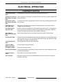
ELECTRICAL OPERATION . . . . . . . . . . . . . . . . . . . . . . . . . . . . . . . . . . . . . . . . . . . . . . . . . . . . . . . . . . . . . . . . . . . . . . . . . . . . . . . . 68
COMPONENT FUNCTION . . . . . . . . . . . . . . . . . . . . . . . . . . . . . . . . . . . . . . . . . . . . . . . . . . . . . . . . . . . . . . . . . . . . . . . . . . . . 68
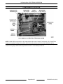
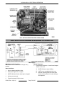
COMPONENT LOCATION . . . . . . . . . . . . . . . . . . . . . . . . . . . . . . . . . . . . . . . . . . . . . . . . . . . . . . . . . . . . . . . . . . . . . . . . . . . . . 69
F45476 Rev. A (0313)
Page 4 of 85
HS Series Slicer
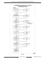
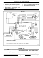
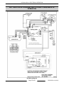
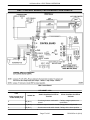
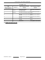
HS6 - ELECTRICAL DIAGRAM & SEQUENCE OF OPERATION . . . . . . . . . . . . . . . . . . . . . . . . . . . . . . . . . . . . . . .
HS6 SEQUENCE OF OPERATION . . . . . . . . . . . . . . . . . . . . . . . . . . . . . . . . . . . . . . . . . . . . . . . . . . . . . . . . . . . . . . . .
HS7 - CONTROL BOARD, LED & ERROR CODE CHARTS . . . . . . . . . . . . . . . . . . . . . . . . . . . . . . . . . . . . . . . . . . . .
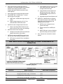
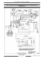
HS7 - ELECTRICAL DIAGRAM, SWITCH CHART & SEQUENCE OF OPERATION . . . . . . . . . . . . . . . . . . . . .
HS7 SEQUENCE OF OPERATION . . . . . . . . . . . . . . . . . . . . . . . . . . . . . . . . . . . . . . . . . . . . . . . . . . . . . . . . . . . . . . . .
HS8 - ELECTRICAL DIAGRAM, SWITCH CHART & SEQUENCE OF OPERATION . . . . . . . . . . . . . . . . . . . . .
HS8 SEQUENCE OF OPERATION . . . . . . . . . . . . . . . . . . . . . . . . . . . . . . . . . . . . . . . . . . . . . . . . . . . . . . . . . . . . . . . .
HS9 - CONTROL BOARD, LED & ERROR CODE CHARTS . . . . . . . . . . . . . . . . . . . . . . . . . . . . . . . . . . . . . . . . . . . .
HS9 - ELECTRICAL DIAGRAM, SWITCH CHART & SEQUENCE OF OPERATION . . . . . . . . . . . . . . . . . . . . .
HS9 SEQUENCE OF OPERATION . . . . . . . . . . . . . . . . . . . . . . . . . . . . . . . . . . . . . . . . . . . . . . . . . . . . . . . . . . . . . . . .
70
70
71
73
74
75
76
77
79
80
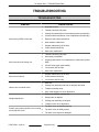
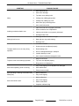
TROUBLESHOOTING . . . . . . . . . . . . . . . . . . . . . . . . . . . . . . . . . . . . . . . . . . . . . . . . . . . . . . . . . . . . . . . . . . . . . . . . . . . . . . . . . . . . . 82
TROUBLESHOOTING . . . . . . . . . . . . . . . . . . . . . . . . . . . . . . . . . . . . . . . . . . . . . . . . . . . . . . . . . . . . . . . . . . . . . . . . . . . . . . . . . 82
© HOBART SERVICE 2013
Page 5 of 85
F45476 Rev. A (0313)
HS Series Slicer - GENERAL
GENERAL
•
This manual is for the Hobart HS Series Slicer.
Procedures in this manual will apply to all models
unless specified.
Carriage Home Switch - The knife motor will not
start unless carriage unit is in home position.
(HS7 home for auto only, HS8, HS9)
•
All information, illustrations and specifications
contained in this manual are based on the latest
product information available at the time of printing.
Interlock Switch - When carriage is interlocked,
knife motor will only run while the ON button is
pressed. (HS8, HS9)
•
Gauge Plate Closed To Stop Switch - Turns off
knife motor when gauge plate is closed from
open position. (HS8, HS9)
•
Knife Reset Switch - Turns off knife motor if
carriage tray is inactive for 30 seconds. (HS8,
HS9)
•
No voltage release - Requires the slicer to be
manually re-started after a power interruption.
INTRODUCTION
Home Position
Many procedures state the carriage transport
assembly should be moved to home position. The
carriage transport assembly is in home position when
it is pulled all the way to the operator end of the slicer.
Models
HS6 Manual
HS6N* Manual
HS7 Automatic
HS7N* Automatic
HS8 Manual
HS8N* Manual
HS9 Automatic
HS9N* Automatic
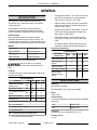
Electrical Components
SLICER MODELS
Electrical
Components
*N models have a non-removable knife.
The slicer knife is very sharp.
Exercise extreme caution when working near the
knife.
Features
Listed are the finish, features and option differences
between the models.
HS6
HS7
HS8
HS7
HS8
HS9
1MTR Knife Motor X
X
X
X
Carriage Home
Switch
X
X
X
Interlock Switch
X
X
Knife Reset Switch
X
X
Gauge Plate
Closed To Stop
Switch
X
X
SLICER MODELS
Features
HS6
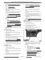
SPECIFICATIONS
HS9
Sharpener Housing
Mount Finish
BB
BB
A
A
Electrical
100-120/60/1 (5 amps)
Slicer Base Finish
BB
BB
A
A
200-240/50/60/1 (2.5 amps) also available.
Tray Support Assembly
BB
Finish
BB
A
A
Automatic Shut-Off
N/A
N/A
S
S
Motor
Knife ½ H.P.
Cleaning Leg
S
S
S'
S'
S'= Lift Assist Cleaning Leg
Cord and Plug
A six foot flexible three wire cord and plug is standard
equipment.
N/A = Not available.
120V
NEMA 5-15P
S = Standard on this model.
230V
NEMA 6-15P
A = Anodized finish.
Thickness
Adjustable to slice a thickness up to 1-1/4".
BB = Polished and ball burnished finish.
•
10 rib Poly V-Belt driven knife.
F45476 Rev. A (0313)
Carriage Travel
12-1/2"
Page 6 of 85
HS Series Slicer - GENERAL
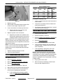
Stroke Count
Speed #1 Low
30
Speed #2 Medium Low
40
Speed #3 Medium High
50
Speed #4 High
60
*Numbers reflect full strokes per minute.
Knife Speed
Knife speed - 430 RPM
Knife Dimension
13"(new) to 12-3/4"(min.)
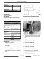
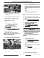
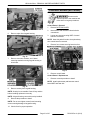
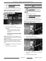
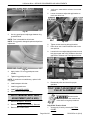
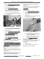
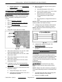
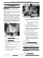
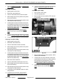
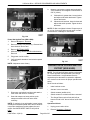
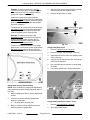
Fig. 1
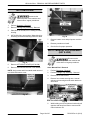
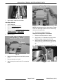
Interlock Service Tool Installation Instructions
Knife Sharpener
Top mounted removable two Borazon stone type.
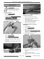
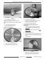
1.
Weight
Approximate shipping weight 135 lbs. , Net 103 lbs.
Press down tray arm interlock and Insert interlock
service tool as shown . Transport is now free to
move without the tray.
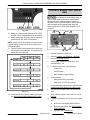
LUBRICATION
Lubricants
Where Used
Carriage Transport
Lubriplate FMO- 200Assembly- in wick for slide
AW
rod.
Part No. 437906
Lightly coat- index seal.
Lubriplate SFL-000
NSF H-1
Lightly coat- meat grip slide
rod.
Lubriplate SFL-1
NSF H-1
Lightly coat- meat grip shaft.
Chevron ALC-EPO
Coat- index mechanism shaft,
index cam grooves, gauge
plate boot.
Lubriplate FGL-0
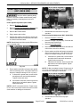
Fig. 2
2.
Lightly coat- index shaft, knife
shaft boot.
The transport must be returned to home position
in order to remove interlock service tool. Pull out
tool.
Special Tools
TOOLS
1.
Required Tools
•
Standard set of hand tools.
Wire Harness (Jumper Plug) Part No.
00-915276.
2.
Loctite® Primer, obtain locally.
•
NOTE: Apply Loctite primer any time Loctite is used.
•
VOM with A/C current tester (any quality VOM
with a sensitivity of at least 20,000 ohms per volt
can be used).
Interlock Service Tool, Part No. 00-915522.
Inserted into carriage transport assembly to allow
movement during times when carriage tray unit
is removed but carriage transport assembly
needs to be moved for removal or adjustment of
parts.
3.
Loctite® 603™, obtain locally.
4.
Loctite® 222™, obtain locally.
5.
Loctite® 242™, obtain locally.
6.
Loctite® 271™, obtain locally.
7.
Dow Corning® RTV 732™, obtain locally.
8.
Never-Seez® Food Grade NSWT-14, Part No.
00-511907
9.
Torque Wrench (20-400 in.-lbs)
Page 7 of 85
F45476 Rev. A (0313)
HS Series Slicer - GENERAL
10. Field Service Grounding Kit (available locally)
11. Knife Removal Tool, Part No. 00-914758
12. V-Belt Tension Tester, Part No. 00-874356.
Used to apply 10 lbs of force to top knife cover in
rulon screw adjustment.
13. Drive Belt Tension Gauge, Part No. 00-477756.
F45476 Rev. A (0313)
Page 8 of 85
HS Series Slicer - REMOVAL AND REPLACEMENT PARTS
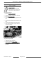
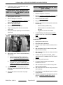
REMOVAL AND REPLACEMENT PARTS
SHARPENER
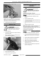
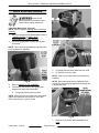
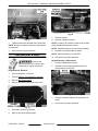
Disconnect the
electrical power to the machine and
follow lockout / tagout procedures.
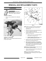
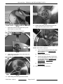
Sharpener - Removal
1.
Lift up to remove sharpener from sharpener
mount.
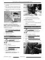
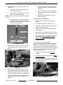
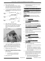
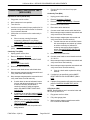
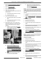
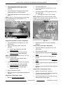
Fig. 4
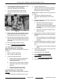
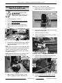
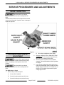
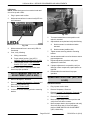
NOTE: Refer to graphic #AI 2028 for disassembly.
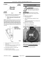
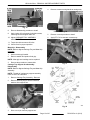
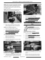
1.
Remove two screws (25) to remove cover
assembly (24).
2.
Remove screw (23) from housing assembly (1)
to remove sharpener handle (22).
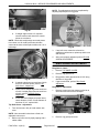
3.
Squeeze together split end of push rod (11) and
push it from actuator (6).
A.
Remove push rod (11) by freeing rod ball
from socket on truing arm (15).
B.
Squeeze together split end of rod (11) and
pull truing arm spring (10) from rod.
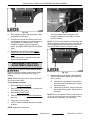
Fig. 3
Sharpener - Disassembly
NOTE: Remove only those parts required to access
part(s) being replaced.
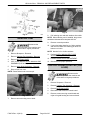
4.
Remove screw (14) to remove actuator (6) and
spring (9) from housing assembly (1).
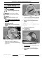
5.
Place a screw driver blade in end of grinding
wheel shaft (4). Remove (R.H.) retaining screw
(13) from shaft to remove grinding wheel (12) and
allow plunger (2) and spring (3) to be removed
from housing assembly (1).
NOTE: When reinstalling retaining screw (13) Loctite
No. 222 must be used on threads.
6.
Remove retaining ring (5) and pull grinding wheel
shaft (4) from plunger (2).
NOTE: The sleeve bearings in plunger are not
serviceable. Plunger and bearings must be replaced
as an assembly (2).
Page 9 of 85
F45476 Rev. A (0313)
HS Series Slicer - REMOVAL AND REPLACEMENT PARTS
TOP KNIFE COVER
Disconnect the
electrical power to the machine and
follow lockout / tagout procedures.
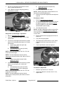
Fig. 5
7.
Remove retaining ring (not numbered) to remove
truing arm (15) from housing assembly (1).
A.
Remove screw (18) from truing arm (15) to
remove truing stone (16) and truing stone
spring (17).
NOTE: When installing truing stone to truing arm and
push rod assembly, spring and truing stone must be
assembled together. Longest leg of spring should be
against truing stone with bend in spring nearest truing
stone screw. Truing stone screw must be installed so
screw head will be toward housing assembly after final
assembly.
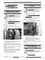
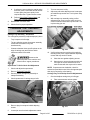
The slicer knife is very sharp.
Exercise extreme caution when working near the
knife.
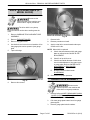
Top Knife Cover - Removal
1.
Close gauge plate.
2.
Move carriage transport assembly to home
position.
3.
Grasp cover knob and lift cover out and up from
magnet and location pins.
Top Knife Cover - Replacement
1.
Place cover on locating pins.
2.
Place cover knob down onto magnet.
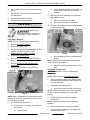
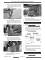
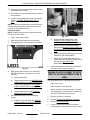
Fig. 6
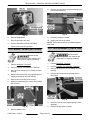
8.
9.
Fig. 7
Remove screw (8) to remove roller (7) from
actuator (6).
Remove screws (21) to remove housing spring
clip (19) from housing assembly (1).
10. Reassemble sharpener in reverse order.
NOTE: If top knife cover is being replaced with a new
cover, perform TOP KNIFE COVER CHECK/
ADJUSTMENT.
3.
11. Reinstall sharpener on slicer.
12. Check for proper knife sharpener operation.
F45476 Rev. A (0313)
Page 10 of 85
Check slicer for proper operation.
HS Series Slicer - REMOVAL AND REPLACEMENT PARTS
RING GUARD
Disconnect the
electrical power to the machine and
follow lockout / tagout procedures.
Ring Guard - Removal
1.
Remove TOP KNIFE COVER.
2.
Remove ring guard cover.
3.
Remove knife per KNIFE- REMOVABLE (NON N
- MODEL SLICER) or KNIFE - NON
REMOVABLE (N - MODEL SLICER).
4.
Remove plug buttons and screws to free knife
ring guard from sharpener housing mount.
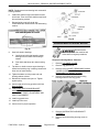
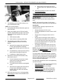
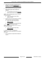
Fig. 10
Ring Guard - Replacement
1.
Reverse removal procedure to install.
2.
Apply Loctite 271 to ring guard post screw.
Torque screw 20 in.-lbs.
3.
Check and adjust height of ring guard to knife
face RING GUARD ADJUSTMENT.
4.
Check slicer for proper operation.
Knife Edge Protector Lock - Removal &
Replacement
Fig. 8
5.
Remove BOTTOM COVER.
6.
Remove KNIFE MOTOR AND BRACKET
ASSEMBLY.
7.
Remove screws securing transport roller bar to
slicer base.
8.
Remove screws (2 places) securing ring guard to
slicer base.
1.
Lift off sharpener.
2.
Remove TOP KNIFE COVER.
3.
Remove ring guard cover.
4.
Remove knife per KNIFE- REMOVABLE (NON N
- MODEL SLICER) or KNIFE - NON
REMOVABLE (N - MODEL SLICER).
5.
Remove screw securing lock.
Fig. 11
Fig. 9
6.
Remove knife edge protector lock and torsion
spring lock.
7.
Reverse procedure to install.
8.
Apply Loctite primer and Loctite 271 to threads of
screw.
Page 11 of 85
F45476 Rev. A (0313)
HS Series Slicer - REMOVAL AND REPLACEMENT PARTS
CARRIAGE TRAY AND MEAT GRIP
ASSEMBLY
Disconnect the
electrical power to the machine and
follow lockout / tagout procedures.
Carriage Tray Assembly - Removal
NOTE: Refer to diagram Carriage Tray and Meat Grip
Assembly.
Fig. 12
NOTE: Knife edge protector lock is spring-loaded.
Tighten screw until knife edge protector lock will not
rotate freely, then back off until just free.
9.
Check slicer for proper operation.
DEFLECTOR
1.
Move carriage transport assembly to home
position.
2.
Unscrew support tray knob.
3.
Tilt carriage tray and tray support assembly away
from slicer until it stops.
4.
Grasp assembly with both hands and lift straight
up.
5.
Reverse procedure to install.
NOTE: When installing carriage tray assembly, verify
that number stamped or etched into key plate of
carriage tray matches the last three digits of the serial
number on the slicer's data plate.
Disconnect the
electrical power to the machine and
follow lockout / tagout procedures.
Carriage Tray - Disassembly
NOTE: Refer to diagram Carriage Tray and Meat Grip
Assembly.
1.
Lift off sharpener.
2.
Pull bottom of deflector from magnet. Rotate up
and out from knife.
3.
Remove deflector when pin in deflector mount
lines up with slot in deflector.
1.
Remove Carriage Tray Assembly - Removal.
2.
Remove two shoulder screws and washers to
free carriage tray assembly from tray support
arm.
3.
Unscrew slide rod knob from mounting block.
4.
Slide grip arm assembly from slide rod.
5.
Slide rod from carriage tray assembly.
6.
Remove screws securing support bracket &
support block to tray.
7.
Remove screws and washers securing thumb
guard to carriage tray.
Fig. 13
4.
Reverse procedure to install.
5.
Check slicer for proper operation.
F45476 Rev. A (0313)
Page 12 of 85
HS Series Slicer - REMOVAL AND REPLACEMENT PARTS
4.
Remove screws securing handle to carriage tray.
Fig. 14
8.
Reverse disassembly procedure to install.
9.
Apply Loctite 242 to threads of shoulder screws,
mounting block and tighten slide rod.
10. Adjust CARRIAGE TRAY ASSEMBLY
ADJUSTMENTS.
Fig. 16
5.
Reverse removal procedure to install.
6.
Apply RTV 732 to area arm contacts tray.
11. Torque shoulder screws to 80 in-lbs.
12. Check slicer for proper operation.
Meat Grip - Disassembly
NOTE: Refer to diagram Carriage Tray and Meat Grip
Assembly.
1.
Unscrew meat grip handle.
2.
Remove washer and product feed grip.
NOTE: Meat grip arm bushings can be replaced.
3.
Reverse the procedure to reassemble.
Fig. 17
Carriage Tray Support Arm Assembly Disassembly
NOTE: Refer to diagram Carriage Tray and Meat Grip
Assembly.
NOTE: Threads of carriage tray support assembly
knob are not to be lubricated.
1.
Remove Carriage Tray Assembly - Removal.
2.
Remove retaining ring to remove knob and
washers from support arm.
Fig. 18
Fig. 15
3.
Drive out roll pin from tray support arm.
Page 13 of 85
F45476 Rev. A (0313)
HS Series Slicer - REMOVAL AND REPLACEMENT PARTS
KNIFE- REMOVABLE (NON N MODEL SLICER)
Disconnect the
electrical power to the machine and
follow lockout / tagout procedures.
The slicer knife is very sharp.
Exercise extreme caution when working near the
knife.
Fig. 20
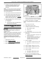
Knife - Removal
NOTE: Replace knife if it is less than 12-3/4"
diameter.
1.
Remove CARRIAGE TRAY AND MEAT GRIP
ASSEMBLY.
2.
Remove TOP KNIFE COVER.
3.
Remove ring guard cover.
4.
Manually rotate knife until arrow is pointing at
small pin.
6.
Push knife removal tool inward until locking pins
bottom onto knife hub. Then turn knife removal
tool handle CCW until it stops.
7.
With knife removal tool engaged lift knife from
machine.
8.
Reverse procedure to install.
NOTE: Make sure line on knife shaft is pointing
toward small pin shown above in graphic 19044 before
installing knife.
9.
Check slicer for proper operation.
Knife - Replacement
1.
Tape edge of knife.
Fig. 19
5.
Position knife removal tool with locator pin
inserted into knife hole clearing three guide pins
on ring guard.
F45476 Rev. A (0313)
Fig. 21
2.
Remove knife per KNIFE- REMOVABLE (NON N
- MODEL SLICER).
3.
Place 7/8" socket on a flat stable surface.
4.
Press knife and tool onto socket compressing
three pins.
Page 14 of 85
HS Series Slicer - REMOVAL AND REPLACEMENT PARTS
Fig. 24
Fig. 22
5.
Turn handle CW until it stops.
10. Turn handle CCW until it stops.
NOTE: Knife will drop over socket onto table.
NOTE: Carefully dispose of knife in replacement knife
box.
6.
Tape edge of replacement knife.
7.
Orient clamp plate as shown.
NOTE: Reuse clamp plate.
11. Reverse removal procedure as outlined under
KNIFE (NON – MODELS) to install.
12. Check slicer for proper operation.
Knife Replacement (Knife Removal Tool
Unavailable)
1.
Remove carriage tray assembly as outlined
under CARRIAGE TRAY AND MEAT GRIP
ASSEMBLY.
2.
Remove top knife cover as outlined under TOP
KNIFE COVER.
3.
Remove ring guard cover.
4.
Use interlock service tool to disengage interlocks
so that gauge plate can be opened. Open gauge
plate.
5.
Tape knife edge.
Fig. 23
8.
Place knife onto knife removal tool.
9.
Compress three pins with 7/8" socket.
Fig. 25
6.
Page 15 of 85
Rotate knife removal clamp plate CCW by
tapping with a brass punch and hammer.
F45476 Rev. A (0313)
HS Series Slicer - REMOVAL AND REPLACEMENT PARTS
Fig. 29
Fig. 26
7.
When knife removal clamp plate lines up with
knife clamp nut, remove knife.
8.
Align clamp nut line to top cover pin.
11. Rotate clamp plate CW with brass punch until
large holes line up with cutout in knife.
Fig. 30
NOTE: When knife is replaced.
A.
Check clearance between knife and gauge
plate as outlined under GAUGE PLATE
ADJUSTMENT.
B.
Check fit of top knife cover.
C.
Check that outside diameter of knife does
not rub inside diameter of ring guard cover
or gauge plate. Refer to GAUGE PLATE
ADJUSTMENT or RING GUARD
ADJUSTMENT.
D.
Sharpen knife as outlined under
SHARPENING.
Fig. 27
9.
Install knife onto locating pins so that arrow also
points to top cover pin.
12. Check slicer for proper operation.
Fig. 28
10. Install clamp plate with large holes as shown
F45476 Rev. A (0313)
Page 16 of 85
HS Series Slicer - REMOVAL AND REPLACEMENT PARTS
KNIFE - NON REMOVABLE (N MODEL SLICER)
Disconnect the
electrical power to the machine and
follow lockout / tagout procedures.
The slicer knife is very sharp.
Exercise extreme caution when working near the
knife.
1.
Remove CARRIAGE TRAY AND MEAT GRIP
ASSEMBLY.
Fig. 32
2.
Remove TOP KNIFE COVER.
7.
Remove knife.
3.
Remove ring guard cover.
8.
Reverse procedure to install.
4.
Use interlock service tool to turn interlocks off so
that gauge plate can be opened. Open gauge
plate.
9.
Apply Loctite 242 to screw threads and torque
screws to 45 in-lbs.
5.
Tape knife edge.
NOTE: When knife is replaced.
A.
Check clearance between knife and gauge
plate as outlined under GAUGE PLATE
ADJUSTMENT.
B.
Check fit of top knife cover.
C.
Check that outside diameter of knife does
not rub inside diameter of ring guard cover
or gauge plate. Refer to GAUGE PLATE
ADJUSTMENT or RING GUARD
ADJUSTMENT.
D.
Sharpen knife as outlined under
SHARPENING.
10. Check slicer for proper operation.
GAUGE PLATE ASSEMBLY
Fig. 31
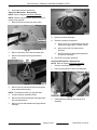
6.
Remove four screws.
Disconnect the
electrical power to the machine and
follow lockout / tagout procedures.
1.
Remove knife per KNIFE- REMOVABLE (NON N
- MODEL SLICER) or KNIFE - NON
REMOVABLE (N - MODEL SLICER).
2.
Pull down gauge plate bottom boot from gauge
plate support.
3.
Remove gauge plate bolts & washers.
Page 17 of 85
F45476 Rev. A (0313)
HS Series Slicer - REMOVAL AND REPLACEMENT PARTS
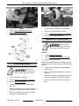
8.
Remove four screws securing lifter bearing block
to auto drive assembly.
Fig. 35
Fig. 33
4.
Remove gauge plate.
9.
5.
Reverse procedure to install.
10. Apply loctite 242 to all screws.
6.
Perform GAUGE PLATE ADJUSTMENT.
7.
Check slicer for proper operation.
NOTE: Ensure both bushings are installed against
lifter arms.
LIFT ASSIST LEVER (HS7 & HS9)
Reverse procedure to install.
LIFT LEG ASSEMBLY (HS6 & HS8)
Disconnect the
electrical power to the machine and
follow lockout / tagout procedures.
Disconnect the
electrical power to the machine and
follow lockout / tagout procedures.
1.
Perform Sharpener - Removal.
2.
Perform Carriage Tray Assembly - Removal.
3.
Place slicer on its side, so it is resting on motor
housing.
4.
Remove screw from lifter arm (opposite side of
handle) and slide off arm and bushing.
5.
Remove screw securing lever to slicer.
6.
Slide lever with bushings out from slicer (handle
side of lever).
1.
Perform Sharpener - Removal.
2.
Perform Carriage Tray Assembly - Removal.
3.
Place slicer on its side, so it is resting on motor
housing.
4.
Remove two screws securing lift leg block to
slicer base.
Fig. 36
Fig. 34
7.
5.
Remove screw securing leg and spring to block
assembly.
6.
Reverse the procedure to install.
Reomve bottom cover.
F45476 Rev. A (0313)
Page 18 of 85
HS Series Slicer - REMOVAL AND REPLACEMENT PARTS
BOTTOM COVER
Disconnect the
electrical power to the machine and
follow lockout / tagout procedures.
1.
Perform Sharpener - Removal.
2.
Remove Carriage Tray Assembly - Removal
3.
Place slicer on its side, so it is resting on motor
housing.
4.
HS7 & HS9 Only. remove Auto / Manual knob by
loosening set screw and sliding knob from shaft.
Fig. 39
7.
Remove bottom cover and pull power cord thru
cover.
8.
Reverse procedure to install.
9.
Check slicer for proper operation.
AUTO / MANUAL ROD ASSEMBLY
(HS7 & HS9)
Disconnect the
electrical power to the machine and
follow lockout / tagout procedures.
Fig. 37
5.
Remove LIFT ASSIST LEVER (HS7 & HS9).
6.
Remove 4 screws and unscrew 4 foot stands.
NOTE: Only screws and 2 foot stands need removed
on HS6 & HS8 bottom cover.
Auto / Manual Rod - Removal
1.
Perform Sharpener - Removal.
2.
Perform Carriage Tray Assembly - Removal.
3.
Remove BOTTOM COVER.
4.
Remove four screws securing auto / manual
selector rod mounting block & switch bracket to
slicer base.
Fig. 38
Fig. 40
5.
Page 19 of 85
While holding end of rod (selector knob end) pull
opposite end away from base to remove auto /
manual selector rod.
F45476 Rev. A (0313)
HS Series Slicer - REMOVAL AND REPLACEMENT PARTS
NOTE: Take note of close to stop actuator and index
cam position for installation. Gauge plate in the closed
position, actuator will be close to switch housing.
Gauge plate in open position, actuator will be away
from switch housing.
NOTE: Hold index cam close to stop actuator in place
with finger to prevent pin from propelling away.
Fig. 43
Check slicer for proper operation.
6.
Perform GAUGE PLATE CLOSED TO STOP
SWITCH 2S ADJUSTMENT (HS8 & HS9).
7.
Perform AUTO / MANUAL BELT GRIP
ADJUSTMENT (HS7 & HS9).
AUTO DRIVE MECHANISM (HS7 &
HS9)
Fig. 41
6.
5.
Note location of lead wires to auto / manual
switch & gauge plate switch, and disconnect.
NOTE: N.O. & COM terminals used.
7.
Reverse removal procedure to install.
8.
Perform GAUGE PLATE CLOSED TO STOP
SWITCH 2S ADJUSTMENT (HS8 & HS9).
9.
Perform AUTO / MANUAL SWITCH 5S
ADJUSTMENT (HS7 & HS9)
Auto / Manual Rod - Disassembly
Disconnect the
electrical power to the machine and
follow lockout / tagout procedures.
Auto Drive Mechanism - Removal
NOTE: Refer to diagram Auto Drive Assembly.
1.
Perform Sharpener - Removal.
2.
Perform Carriage Tray Assembly - Removal.
3.
Remove BOTTOM COVER.
1.
Remove two short and one long screws securing
bracket to mounting block.
2.
Reverse procedure to install.
4.
3.
Verify both mounting bracket screws at middle
location of slotted holes.
Remove screw securing lead wires restraining
clip to auto drive assembly.
5.
Remove screws securing auto drive assembly.
Fig. 44
6.
Carefully lay auto drive assembly down on table
surface.
7.
Remove screws securing lead wire retaining
clips from auto drive assembly & slicer base.
Fig. 42
4.
Install auto drive mounting block & switch bracket
with rod hole position further from the slicer base.
F45476 Rev. A (0313)
Page 20 of 85
HS Series Slicer - REMOVAL AND REPLACEMENT PARTS
8.
Disconnect lead wire connectors.
Auto Drive Mechanism - Disassembly
NOTE: Refer to diagram Auto Drive Assembly.
NOTE: Remove only those parts required to access
part(s) being replaced.
1.
Remove screws securing auto drive motor.
Fig. 47
8.
Remove tensioner assembly.
9.
Reverse procedure to assemble.
Fig. 45
2.
Remove auto drive motor and secondary belt.
3.
Remove set screws securing transmission
pulley.
A.
Apply Loctite 271 to transmission pulley set
screws and support plate / bracket screws.
B.
Apply Loctite 242 to all other screws
removed.
C.
Set belt tension by applying hand pressure
to tensioner assembly.
10. Check slicer for proper operation.
Auto Drive Mechanism - Replacement
NOTE: Refer to diagram Auto Drive Assembly.
1.
Reverse removal procedure to install.
2.
Place primary auto drive belt in clip assembly.
Fig. 46
4.
Remove screws, washers & plate securing auto
drive transmission housing.
NOTE: Transmission housing on opposite side.
5.
Loosen tensioner assembly screws.
6.
Remove auto drive transmission housing primary
belt, and transmission.
7.
Remove screws and washers securing tensioner
assembly.
Fig. 48
3.
Page 21 of 85
Install lead wire retaining clips to auto drive
assembly.
F45476 Rev. A (0313)
HS Series Slicer - REMOVAL AND REPLACEMENT PARTS
Fig. 51
Fig. 49
4.
Perform AUTO / MANUAL BELT GRIP
ADJUSTMENT (HS7 & HS9).
5.
Check slicer for proper operation.
7.
Perform ROLLER BEARING ADJUSTMENT.
8.
Reverse removal procedure to install.
9.
Perform OVERTURN SCREW ADJUSTMENT.
10. Check slicer for proper operation.
TRANSPORT & SLIDE ROD
Disconnect the
electrical power to the machine and
follow lockout / tagout procedures.
Removal
Fig. 50
Perform Sharpener - Removal.
2.
Perform Carriage Tray Assembly - Removal.
3.
Remove BOTTOM COVER.
NOTE: (HS7 & HS9 models) The transport service
tool must be used to move transport away from home
position.
ROLLER BEARING
Disconnect the
electrical power to the machine and
follow lockout / tagout procedures.
1.
Perform Sharpener - Removal.
2.
Perform Carriage Tray Assembly - Removal.
3.
Remove BOTTOM COVER.
4.
( HS& & HS9) Remove Auto / Manual Rod Removal.
5.
Remove 8 screws securing transport roller bar to
slicer base. Slide bar out from roller bearing.
6.
Remove retaining ring and pull roller bearing
assembly from adjusting screw.
F45476 Rev. A (0313)
1.
4.
Remove AUTO / MANUAL ROD ASSEMBLY
(HS7 & HS9).
5.
Move carriage transport assembly to middle of
slide rod.
6.
Remove 8 screws securing transport roller bar to
slicer base. Slide bar out from roller bearing.
7.
Remove two bolts to free slide rod from slicer
base
Page 22 of 85
HS Series Slicer - REMOVAL AND REPLACEMENT PARTS
Fig. 52
6.
Remove two screws and magnet block (HS7 &
HS9).
7.
Remove four screws and washers to remove belt
grip bracket and the auto drive clutch clip (HS7
&HS9).
8.
Remove retaining clip and interlock extention
spring.
9.
Punch out pin from transport securing tray
interlock assembly (HS8 & HS9).
8.
Lift slide rod and carriage transport assembly
from slicer base.
NOTE: Transport at this point is available as a service
part.
9.
Remove washers and bumpers from the slide
rod.
10. Reverse disassembly procedure to assemble.
10. Remove slide rod from carriage transport
assembly.
11. Apply Lubriplate FMO- 200-AW to slide rod and
wick.
12. Perform ROLLER BEARING ADJUSTMENT.
11. Reverse procedure to install.
NOTE: Ensure auto drive belt installed between auto
drive belt clip & auto drive belt bracket.
12. Perform AUTO / MANUAL BELT GRIP
ADJUSTMENT (HS7 & HS9).
13. Perform OVERTURN SCREW ADJUSTMENT.
14. Perform AUTO / MANUAL BELT GRIP
ADJUSTMENT (HS7 & HS9).
15. Perform CARRIAGE TRAY ASSEMBLY
ADJUSTMENTS.
13. Verify CARRIAGE TRAY ASSEMBLY
ADJUSTMENTS.
16. Check for proper operation.
KNIFE MOTOR AND BRACKET
ASSEMBLY
14. Verify OVERTURN SCREW ADJUSTMENT.
15. Check slicer for proper operation.
Transport - Disassembly
1.
Remove wick from transport assembly.
Disconnect the
electrical power to the machine and
follow lockout / tagout procedures.
NOTE: Transport bearings can be replaced and or
included with transport assembly.
2.
Remove retaining ring & roller bearing.
3.
Remove screw securing adjustment screw to
transport.
Knife Motor and Bracket - Removal
Fig. 53
4.
Remove the jam nut and over turn set screw.
5.
Remove jam nuts and set screws from transport.
1.
Perform Sharpener - Removal.
2.
Perform Carriage Tray Assembly - Removal.
3.
Remove BOTTOM COVER.
4.
Remove AUTO DRIVE MECHANISM (HS7 &
HS9).
5.
Note the color and location of motor lead wires
and disconnect them.
6.
Remove POLY-V BELT.
7.
Remove three bolts holding motor plate/motor
and gasket assembly to slicer base.
8.
Tilt assembly and remove motor & bracket
assembly from slicer base.
9.
Note location of pulley on motor shaft.
Page 23 of 85
F45476 Rev. A (0313)
HS Series Slicer - REMOVAL AND REPLACEMENT PARTS
10. Loosen two set screws and remove belt pulley
from shaft.
11. Note location and type of washers with screws
and relationship of motor plate to motor leads.
12. Remove screws and gasket to free motor plate
from motor.
Fig. 55
6.
Lift capacitor and end cap from bracket.
7.
Remove end cap and disconnect lead wires.
Capacitor - Replacement
Fig. 54
Knife Motor and Bracket - Replacement
NOTE: It is recommended that the motor gasket be
replaced anytime the motor is replaced. When
installing a new motor gasket, remove backing from
gasket before installation.
1.
Reverse removal procedure to assemble and
perform POLY- V BELT ADJUSTMENT AND
PULLEY ALIGNMENT.
2.
Install auto drive assembly.
3.
Install bottom cover.
4.
Check for proper operation.
CAPACITOR
Disconnect the
electrical power to the machine and
follow lockout / tagout procedures.
1.
Reverse removal procedure.
2.
Verify capacitor is secured into position within the
bracket.
3.
Check slicer for proper operation.
ELECTRONIC START SWITCH
Disconnect the
electrical power to the machine and
follow lockout / tagout procedures.
1.
Perform Sharpener - Removal.
2.
Perform Carriage Tray Assembly - Removal.
3.
Remove BOTTOM COVER.
4.
Remove AUTO DRIVE MECHANISM (HS7 &
HS9).
5.
Remove two screws holding start switch bracket
to slicer base.
Capacitor - Removal
1.
Perform Sharpener - Removal.
2.
Perform Carriage Tray Assembly - Removal.
3.
Remove BOTTOM COVER.
4.
If necessary, remove AUTO DRIVE
MECHANISM (HS7 & HS9).
5.
With the blade of a screw driver pry end of
capacitor bracket to free capacitor.
Fig. 56
F45476 Rev. A (0313)
Page 24 of 85
HS Series Slicer - REMOVAL AND REPLACEMENT PARTS
6.
Note location and disconnect start switch lead
wires.
7.
Remove two screws from start switch bracket to
free start switch.
8.
Reverse the procedure to install.
9.
Check slicer for proper operation.
KNIFE SHAFT
B.
9.
Continue tapping upward on knife shaft until
shaft is clear of lower hub and bearing
retainer.
Remove knife shaft assembly from slicer base
and deflector mount.
A.
Remove retaining ring from shaft.
B.
Press upper bearing from knife shaft.
10. Remove screws securing lower hub and bearing
retainer to slicer base.
Disconnect the
electrical power to the machine and
follow lockout / tagout procedures.
Knife Shaft - Removal
NOTE: Refer to diagram Knife Shaft Assembly.
1.
Remove TOP KNIFE COVER.
2.
Remove ring guard cover.
3.
Remove knife per KNIFE- REMOVABLE (NON N
- MODEL SLICER) or KNIFE - NON
REMOVABLE (N - MODEL SLICER).
4.
Remove BOTTOM COVER.
5.
Remove AUTO DRIVE MECHANISM (HS7 &
HS9)
6.
7.
Fig. 58
A.
Remove KNIFE MOTOR AND BRACKET
ASSEMBLY.
Press bearing from lower hub and bearing
retainer.
NOTE: Replacement shaft and lower bearing hub
come with bearings installed.
B.
Remove nut and washer from knife shaft.
Remove six screws securing boot to slicer
base.
Knife Shaft - Replacement
CAUTION Excessive Loctite can damage the
bearings.
NOTE: Refer to diagram Knife Shaft Assembly.
1.
Apply Loctite primer and Loctite #638 between
the shaft and both bearings so they rotate as a
unit after assembly.
2.
Install knife shaft boot and ring.
A.
NOTE: Do Not over tighten screws. Over tightening
screws will deform & separate boot from upper
housing.
Fig. 57
NOTE: Care must be taken not to damage the outside
diameter of the pulley. A wooden block can be used
to aid in tapping out shaft.
8.
Tap upward on knife shaft until pulley can
be removed.
1)
Remove pulley.
3.
Press top bearing on shaft and install the
retaining ring.
NOTE: Replacement shaft comes with bearing
installed.
Protect threads of knife shaft.
A.
Apply Loctite 242 to threads of six screws.
4.
Press lower bearing into lower bearing hub.
5.
Loosely install lower bearing hub and bearing
retainer to slicer base.
Page 25 of 85
F45476 Rev. A (0313)
HS Series Slicer - REMOVAL AND REPLACEMENT PARTS
NOTE: Replacement lower bearing hub comes with
bearing installed.
6.
Install knife shaft through knife shaft boot and
slicer base. Then route knife shaft through lower
hub and bearing retainer.
7.
Reinstall pulley onto knife shaft with
counterbored hub toward lower hub and bearing
retainer.
Fig. 60
SHARPENER HOUSING MOUNT
Fig. 59
8.
9.
Disconnect the
electrical power to the machine and
follow lockout / tagout procedures.
Seat knife shaft & bearings.
A.
Carefully tap knife shaft pressing upper
bearing into slicer base until bearing is
seated.
B.
Push knife shaft down thru lower bearing
hub.
Sharpener Housing Mount - Removal
Tap down on shaft to ensure upper bearing is
seated and retaining ring is making contact with
inner race of lower bearing.
10. Tighten hardware securing lower hub and
bearing retainer to base.
1.
Remove TOP KNIFE COVER.
2.
Remove ring guard cover.
3.
Remove knife per KNIFE- REMOVABLE (NON N
- MODEL SLICER) or KNIFE - NON
REMOVABLE (N - MODEL SLICER).
4.
Remove plug buttons and screws securing
housing mount to knife ring guard.
11. Reinstall lock washer and jam nut. Tighten
against pulley.
12. Check height of knife ring guard to knife face
RING GUARD.
13. Install KNIFE MOTOR AND BRACKET
ASSEMBLY, adjust pulley and poly-V belt
tension POLY- V BELT ADJUSTMENT AND
PULLEY ALIGNMENT.
14. Install ring guard cover.
15. Install top knife cover.
16. Check slicer for proper operation.
Fig. 61
F45476 Rev. A (0313)
5.
Remove KNIFE MOTOR AND BRACKET
ASSEMBLY .
6.
Remove two bolts holding housing mount to
base.
Page 26 of 85
HS Series Slicer - REMOVAL AND REPLACEMENT PARTS
Fig. 62
7.
Pull housing mount from slicer base.
Knife Edge Protector
1.
Lift off sharpener.
2.
Remove TOP KNIFE COVER.
3.
Remove ring guard cover.
4.
Remove knife per KNIFE- REMOVABLE (NON N
- MODEL SLICER) or KNIFE - NON
REMOVABLE (N - MODEL SLICER).
5.
Fig. 64
NOTE: Knife edge protector is spring-loaded. Tighten
screw until knife edge protector will not rotate freely,
then back off until just free.
9.
Check slicer for proper operation.
Sharpener Housing Mount - Installation
Remove screw.
1.
Reverse removal procedure to install.
2.
Apply loctite 271 to threads and torque screws
holding housing mount to base 25 in.-lbs.
3.
Apply loctite 242 to threads and torque screws
securing housing mount to knife ring guard 10 in.lbs.
4.
Seal housing mount to slicer base with RTV 732.
Fig. 63
6.
Remove knife edge protector and knife protector
spring.
7.
Reverse procedure to install.
8.
Apply Loctite primer and Loctite 271 to threads of
screw.
Page 27 of 85
Fig. 65
F45476 Rev. A (0313)
HS Series Slicer - REMOVAL AND REPLACEMENT PARTS
INDEX SLIDE MECHANISM
Disconnect the
electrical power to the machine and
follow lockout / tagout procedures.
Index Slide Mechanism - Removal
NOTE: Refer to diagram Indexing Slide mechanism
Assembly.
1.
2.
Remove knife per KNIFE- REMOVABLE (NON N
- MODEL SLICER) or KNIFE - NON
REMOVABLE (N - MODEL SLICER).
Fig. 67
Pull down gauge plate boot from special plate
and braket.
NOTE: Take note of gauge plate boot and index slide
boot, orientation for installing.
Fig. 68
5.
Lift gauge plate and index slide boot from slide.
6.
Lift retainer cover from slide.
NOTE: Take note of index slide boot orientation for
installing.
NOTE: When index slide boot is installed Chevron
ALC-EPO grease should be applied to the flange that
is against the base.
Fig. 66
3.
Remove GAUGE PLATE ASSEMBLY.
4.
Loosen three set screws to free gauge plate
support from index slide mechanism.
A.
Pull gauge plate support from slide.
NOTE: When the three set screws in the gauge plate
support are tightened, torque them to 120 in.*lbs.
Ensure they seat on V groove in slide
Fig. 69
7.
F45476 Rev. A (0313)
Page 28 of 85
Remove AUTO DRIVE MECHANISM (HS7 &
HS9).
HS Series Slicer - REMOVAL AND REPLACEMENT PARTS
8.
9.
Turn index knob as required to remove the three
screws holding the index slide/support
mechanism assembly to the slicer base.
Turn index knob to allow the most vertical
movement of slide dowel pin within cam as
possible.
2.
Inspect bushings for burrs.
3.
Carefully insert the three bushings (squeezing
lightly) into the slide mechanism making them
flush with the edges of the casting.
NOTE: Splits in bushings must not line up with slots
in casting.
4.
Lubricate the bushings and index slide
mechanism and slide rod with Chevron ALCEPO.
5.
Insert the index slide rod through the opening in
the support assembly.
Fig. 70
10. Gently tap end of index slide mechanism with a
punch & rubber mallet until dowel pins on index
slide support clear the holes in slicer base.
11. Move pin side of assembly up and out away from
index cam knob until the slide dowel pin is free of
the cam then back toward index knob and lift from
slicer base.
6.
A.
Insert the index slide rod through the
support bore, index slide mechanism
bushings and the other support bore making
both ends of the rod even with the edges of
the casting.
B.
Tighten the set screws in support to fix the
slide rod in place.
Lubricate the anti-rotation rod with Chevron ALCEPO and insert into the index slide mechanism
bushing.
A.
13. Perform GAUGE PLATE ADJUSTMENT.
Install index slide/support mechanism into slicer
base. Move index knob as necessary to tighten
bolts.
14. Check slicer for proper operation.
A.
12. Reverse removal procedure to install.
7.
Insert and tighten the two mounting screws
to secure anti-rotation rod onto the support
assembly.
With assembly in place install the backlash
spring.
Index Slide Mechanism - Disassembly
NOTE: Refer to diagram Indexing Slide mechanism
Assembly.
8.
Install interlock stop bracket. Leave screws loose
for index slide adjustment.
1.
Remove interlock stop bracket.
9.
Install GAUGE PLATE ASSEMBLY
2.
Remove index backlash spring.
3.
Loosen three clamping screws.
10. Perform INDEX SLIDE MECHANISM
ADJUSTMENT.
A.
Remove bolts securing anti-rotation index
rod to support assembly and pull antirotation rod from slide.
B.
Loosen two set screws in support assembly,
and slide the index slide rod from support
assembly.
C.
Remove bushings from index slide
mechanism and anti rotation clamp.
11. Perform GAUGE PLATE ADJUSTMENT.
12. Check slicer for proper operation.
Index Slide Mechanism - Reassembly
NOTE: Refer to diagram Indexing Slide mechanism
Assembly.
1.
Inspect index slide mechanism bores for burrs.
Page 29 of 85
F45476 Rev. A (0313)
HS Series Slicer - REMOVAL AND REPLACEMENT PARTS
Fig. 73
Fig. 71
8.
Pull indexing cam and shim washers from shaft.
NOTE: When indexing cam is installed, the grooves
should be lubricated with Lubriplate 630 AA.
INDEXING CAM
9.
Disconnect the
electrical power to the machine and
follow lockout / tagout procedures.
Reverse removal procedure.
10. If cam rubs braket install up to 6 shim washers
and recheck. Make sure indexing pin does not
bottom out in cam.
NOTE: Nominal is 3 to 6 shim washers.
1.
Remove Sharpener - Removal.
2.
Remove Carriage Tray Assembly - Removal.
11. Perform AUTO / MANUAL BELT GRIP
ADJUSTMENT (HS7 & HS9).
3.
Remove BOTTOM COVER.
12. Perform GAUGE PLATE ADJUSTMENT.
4.
(HS7 & HS9) Remove AUTO / MANUAL ROD
ASSEMBLY (HS7 & HS9).
13. Check slicer for proper operation.
5.
Remove Index Slide Mechanism - Removal.
6.
Drive roll pin from cam.
CONTROL BOARD & KEYPAD (HS6
& HS8)
NOTE: Rotate index knob to access pin.
Disconnect the
electrical power to the machine and
follow lockout / tagout procedures.
1.
Remove Sharpener - Removal.
2.
Remove Carriage Tray Assembly - Removal.
3.
Remove BOTTOM COVER.
4.
Disconnect lead wires from control board.
5.
Remove screws securing control board and
mylar to keypad housing and remove board.
Fig. 72
7.
Remove screw securing cam to shaft.
F45476 Rev. A (0313)
Page 30 of 85
HS Series Slicer - REMOVAL AND REPLACEMENT PARTS
CONTROL BOARD (HS7 & HS9)
Disconnect the
electrical power to the machine and
follow lockout / tagout procedures.
Control Board - Removal
Fig. 74
6.
1.
Remove BOTTOM COVER.
2.
Note location and disconnect electrical wire
connections.
3.
Loosen two screws securing IGBT of control
board to slicer base.
Remove mylar from keypad housing.
NOTE: Heat sink pad will need to be replaced any
time control board is removed.
4.
Remove four screws securing board to slicer.
Fig. 75
7.
Remove 4 screws, washers, and 2 bezel
mounting washers securing keypad housing to
slicer base.
Fig. 77
5.
Remove control board.
Control Board - Replacement
1.
Reverse removal procedure to install.
NOTE: Install replacement pad between control
board IGBT and heat sink.
Fig. 76
8.
Remove overlay from keypad housing.
NOTE: Overlay is not reusable. Clean off any residue
before installing replacement overlay.
NOTE: Keypad housing come with overlay installed.
9.
Reverse the procedure to install.
NOTE: Do not over tighten control board mounting
screws causing damage to keypad housing.
10. Check slicer for proper operation.
Page 31 of 85
F45476 Rev. A (0313)
HS Series Slicer - REMOVAL AND REPLACEMENT PARTS
Fig. 80
Fig. 78
2.
Tighten screws to secure heat sink to slicer base.
NOTE: Do Not over tighten screws securing heat sink
to slicer base.
3.
Check slicer for proper operation.
KEYPAD (HS7 & HS9)
7.
Remove keypad.
8.
Remove overlay from bezel.
NOTE: Overlay is not reusable. Clean off any residue
before installing replacement overlay.
NOTE: Keypad housing come with overlay installed.
9.
Reverse removal procedure to install.
NOTE: Seal lower bezel cover with RTV.
10. Check slicer for proper operation.
Disconnect the
electrical power to the machine and
follow lockout / tagout procedures.
Keypad Housing - Replacement
1.
Perform keypad board removal.
2.
Remove bolts securing keypad housing and
bezel gasket to slicer base.
Keypad Board - Removal
1.
Perform Sharpener - Removal.
2.
Perform Carriage Tray Assembly - Removal.
3.
Remove BOTTOM COVER.
4.
Remove screws securing lower bezel cover.
Fig. 81
3.
Reverse removal & replacement procedures to
install.
4.
Check slicer for proper operation.
Fig. 79
5.
Disconnect electrical connectors.
6.
Remove screws securing keypad.
F45476 Rev. A (0313)
Page 32 of 85
HS Series Slicer - REMOVAL AND REPLACEMENT PARTS
GAUGE PLATE CLOSED TO STOP
SWITCH 2S (HS8 & HS9)
NOTE: N.O. & COM terminals used.
7.
Remove two screws securing switch to auto /
manual selector rod mounting block.
Disconnect the
electrical power to the machine and
follow lockout / tagout procedures.
1.
Perform Sharpener - Removal.
2.
Perform Carriage Tray Assembly - Removal.
3.
Remove BOTTOM COVER.
4.
Remove four screws securing end of auto /
manual selector rod mounting block to slicer
base.
Fig. 84
8.
Remove two short and one long screws securing
bracket to mounting block.
9.
Reverse procedure to install.
10. Verify both mounting bracket screws at middle
location of slotted holes.
Fig. 82
5.
While holding end of rod (selector knob end) pull
opposite end away from base to remove auto /
manual selector rod.
NOTE: Take note of close to stop actuator and index
cam position for installation. Gauge plate in the closed
position, actuator will be close to switch housing.
Gauge plate in open position, actuator will be away
from switch housing.
NOTE: Hold index cam close to stop actuator in place
with finger to prevent pin from propelling away.
Fig. 85
11. Install auto drive mounting block with rod hole
position further from the slicer base.
Fig. 83
6.
Note location of lead wires to auto / manual
switch & gauge plate switch, and disconnect.
Fig. 86
12. Perform GAUGE PLATE CLOSED TO STOP
SWITCH 2S ADJUSTMENT (HS8 & HS9).
Page 33 of 85
F45476 Rev. A (0313)
HS Series Slicer - REMOVAL AND REPLACEMENT PARTS
13. Verify AUTO / MANUAL SWITCH 5S
ADJUSTMENT (HS7 & HS9).
AUTO / MANUAL SWITCH 5S (HS7
& HS9)
14. Verify AUTO / MANUAL BELT GRIP
ADJUSTMENT (HS7 & HS9).
15. Check slicer for proper operation.
Disconnect the
electrical power to the machine and
follow lockout / tagout procedures.
CARRIAGE TRAY INTERLOCK
SWITCH 1S (HS8 & HS9)
Disconnect the
electrical power to the machine and
follow lockout / tagout procedures.
1.
Perform Sharpener - Removal.
2.
Perform Carriage Tray Assembly - Removal.
3.
Remove BOTTOM COVER.
4.
Note location of lead wires and disconnect.
1.
Perform Sharpener - Removal.
2.
Perform Carriage Tray Assembly - Removal.
3.
BOTTOM COVER .
4.
Note location of lead wires and disconnect.
NOTE: N.O. & COM terminals used.
5.
Remove two screws securing switch to auto /
manual rod mounting block.
NOTE: N.O. & COM terminals used.
5.
Remove screws securing switch bracket to slicer
base.
Fig. 88
6.
Reverse procedure to install.
7.
Position switch such that switch actuator is
engaged when auto / manual selector rod is
turned to the auto position.
Fig. 87
6.
Remove screws securing switch to bracket.
7.
Reverse procedure to install.
NOTE: Do not allow rod to bend or damage switch
actuator.
NOTE: Install switch bracket such that mounting
screws positioned at top of slotted holes and tighten
screws.
8.
CARRIAGE HOME SWITCH 3S
( HS7, HS8 & HS9)
NOTE: Do not allow cam interlock pin to deform the
switch actuator when engaged.
NOTE: Do not allow switch to contact index cam. If
so, install shim washers onto index knob shaft.
Nominal is 3 to 6 shim washers.
8.
Disconnect the
electrical power to the machine and
follow lockout / tagout procedures.
Check slicer for proper operation.
1.
F45476 Rev. A (0313)
Check slicer for proper operation.
Page 34 of 85
Perform Sharpener - Removal.
HS Series Slicer - REMOVAL AND REPLACEMENT PARTS
2.
Perform Carriage Tray Assembly - Removal.
3.
Remove BOTTOM COVER.
4.
Note location of lead wires and disconnect.
5.
Remove lock nut securing switch to slicer base.
KNIFE RESET SWITCH 4S (HS8 &
HS9)
Disconnect the
electrical power to the machine and
follow lockout / tagout procedures.
NOTE: Use of double wrenches required during
removal and installation of switch.
1.
Perform Sharpener - Removal.
2.
Perform Carriage Tray Assembly - Removal.
3.
Remove BOTTOM COVER.
4.
Note location of lead wires and disconnect.
5.
Remove lock nut securing switch to slicer base.
NOTE: Use of double wrenches required during
removal and installation of switch.
Fig. 89
6.
Reverse the procedure to install.
7.
Adjust switch using lock nuts to obtain switch
actuation at:
•
Closes at 10mm (3/8") when carriage
moves towards home position. #2 LED
illuminated.
•
Opens at 15mm (9/16") when the carriage
moves away from home position. #2 LED
not illuminated.
NOTE: HS8 slicer does not have diagnostic LED's.
Ohm meter will need to be used to check for continuity
at specified distances.
Fig. 90
6.
Reverse the procedure to install.
7.
Position switch with 6 threads showing below nut.
NOTE: This measurement is taken near rod from end
of transport to rubber bumper. Make sure rubber
bumper is pushed all the way towards the base until it
stops.
8.
Secure lock nuts to a maximum torque setting of
14 inch lbs.
9.
Check slicer for proper operation.
Fig. 91
8.
Secure lock nuts to a maximum torque setting of
14 inch lbs.
9.
Check slicer for proper operation.
Page 35 of 85
F45476 Rev. A (0313)
HS Series Slicer - REMOVAL AND REPLACEMENT PARTS
POLY-V BELT
Disconnect the
electrical power to the machine and
follow lockout / tagout procedures.
Poly-V Belt - Removal
1.
Perform Sharpener - Removal.
2.
Perform Carriage Tray Assembly - Removal.
3.
Remove BOTTOM COVER.
4.
Loosen nuts on belt tensioning adjustment screw
nuts.
5.
Loosen screw holding tensioner bracket to motor
plate.
6.
Loosen screws holding motor plate to motor.
7.
Pivot motor to allow slack in poly-V belt and
remove from pulleys.
Fig. 92
Poly-V Belt - Replacement
1.
Install poly-V belt onto pulleys.
2.
Perform procedures POLY- V BELT
ADJUSTMENT AND PULLEY ALIGNMENT.
3.
Reassemble slicer and check for proper
operation.
F45476 Rev. A (0313)
Page 36 of 85
HS Series Slicer - SERVICE PROCEDURES AND ADJUSTMENTS
SERVICE PROCEDURES AND ADJUSTMENTS
GASKET INSPECTION
The slicer knife is very sharp.
Exercise extreme caution when working near the
knife.
Gaskets shown below must be inspected at intervals
not to exceed 6 months. If gasket is worn or damaged
replace as required.
Fig. 93
D.
TOP KNIFE COVER CHECK/
ADJUSTMENT
The slicer will be operating during
portions of this check. Make certain that the gauge
plate is completely closed anytime the slicer is
running.
The slicer knife is very sharp.
Exercise extreme caution when working near the
knife.
2.
Remove CARRIAGE TRAY AND MEAT GRIP
ASSEMBLY and use tray arm interlock key to
allow slicer to be started.(HS8, HS9)
3.
Check to ensure top knife cover is installed
correctly. The knob should be locked in position
on magnet.
4.
Lay a six inch straight edge near center of top
knife cover and slowly move it toward knife until
straight edge touches outer 1/3 of knife face, or
leading end of straight edge extends beyond
cutting edge of knife.
Top Knife Cover - Check
1.
Slicer has unsatisfactory slice quality.
Perform this procedure anytime:
A.
A new knife is installed.
B.
If product is going under top knife cover.
C.
If product is being torn by top knife cover.
Page 37 of 85
F45476 Rev. A (0313)
HS Series Slicer - SERVICE PROCEDURES AND ADJUSTMENTS
NOTE: Fine adjustments can be accomplished by
adjusting tapered pins on ring guard.
Fig. 94
A.
If straight edge touches 1/3, repeat at
several locations and ensure the contact
points are consistent.
NOTE: Check with straight edge at several places
from center out. All contact points should make
contact at the same relative place within outer 1/3 of
knife edge.
Fig. 96
3.
If top knife cover cannot be reformed to
satisfactory performance, replace top knife cover
and recheck.
4.
After cover properly adjusted, perform RULON
SCREW ADJUSTMENT.
RING GUARD ADJUSTMENT
Ring Guard - Check
1.
Remove TOP KNIFE COVER.
2.
Remove ring guard cover.
3.
Ring guard to knife gap should be 0.120" along
diameter of ring guard.
If gap not achieved, perform Ring Guard Adjustment
Fig. 95
B.
If straight edge does not touch face of knife
at one or more test points, perform Top
Knife Cover - Adjustment.
4.
C.
If knife is new, straight edge must touch face
of knife. If straight edge does not touch face
of knife, perform Top Knife Cover Adjustment.
1.
D.
If knife has been sharpened several times,
check diameter of knife. If knife diameter is
less than 12-3/4", replace knife.
Ring Guard - Adjustment
Remove screws securing transport roller bar to
slicer base and remove from transport.
Top Knife Cover - Adjustment
1.
Turn rulon screw in fully to avoid contact with
cover.
NOTE: Non-removable knives have a fixed nonadjustable rulon screw.
2.
Fig. 97
Reform top knife cover by lightly tapping with a
rubber mallet.
F45476 Rev. A (0313)
2.
Page 38 of 85
Remove ring guard post screw.
HS Series Slicer - SERVICE PROCEDURES AND ADJUSTMENTS
4.
Verify auto / manual drive selector is in manual
position.
5.
Loosen 4 screws to adjust belt grip bracket to
touch auto drive belt.
Fig. 98
3.
Use ring guard post to adjust gap between ring
guard and knife.
NOTE: Post is threaded into slicer base.
NOTE: If ring guard is damaged replace and perform
adjustment.
Fig. 100
6.
Tighten screws securing belt grip bracket.
7.
Place slicer auto / manual selector knob in the
auto position.
8.
Loosen lock nut to adjust belt grip screw to touch
belt grip magnet and 0.005" clearance from belt
grip block to selector rod. Then tighten lock nut.
Fig. 99
4.
Apply Loctite 271 to ring guard post screw
threads.
5.
Tighten ring guard post screw.
NOTE: If results are not satisfactory, replace knife
ring guard
6.
Install transport roller bar.
7.
Install ring guard cover.
8.
Install TOP KNIFE COVER
9.
Check slicer for proper operation.
Fig. 101
9.
Reassembly slicer and check for proper
operation.
POLY- V BELT ADJUSTMENT AND
PULLEY ALIGNMENT
AUTO / MANUAL BELT GRIP
ADJUSTMENT (HS7 & HS9)
Disconnect the
electrical power to the machine and
follow lockout / tagout procedures.
1.
Remove Sharpener - Removal.
2.
Remove Carriage Tray Assembly - Removal.
Poly-V Belt Tension Check
3.
Remove BOTTOM COVER
1.
Page 39 of 85
Access poly-V belt by removing BOTTOM
COVER.
F45476 Rev. A (0313)
HS Series Slicer - SERVICE PROCEDURES AND ADJUSTMENTS
2.
Follow Belt Tension Gauge Instructions to test
belt tension.
A.
B.
Free feeler bar from carrying position by
unscrewing upper sleeve.
Turn upper sleeve until bottom aligns with
the required 50 Lbs. (new belt) or 35 Lbs.
(used belt) of belt tension. Normal tensions
are read on the black scale.
Fig. 102
3.
If bottom of feeler bar is above gauge line,
pull feeler bar down. Tighten belt tension
and re-test.
B.
If bottom of feeler bar is below gauge line,
pull feeler bar down. Loosen belt tension
and re-test.
C.
If bottom aligns with gauge line, proper
tension is present.
Position feeler bar perpendicular to upper
sleeve and pull feeler bar down.
NOTE: Feeler bar must be moved to bottom before
each test.
C.
A.
Align feeler bar along belt close to the center of
the span between the center lines of the two
pulleys.
Poly-V Belt Tension Adjustment
1.
Loosen nuts on belt tensioning adjustment
screw.
2.
Loosen screws that allow motor to pivot.
3.
Pivot motor in proper direction by adjusting belt
tensioning adjustment screw.
4.
Tighten nuts on adjustment screw and motor
mounting bolts.
5.
Re-test belt tension. Repeat until 50 Lbs. (new
belt) or 35 Lbs. (used belt) belt tension is present.
6.
Check pulley alignment and align if necessary, as
outlined under Poly-V Belt Adjustment and
PULLEY Alignment.
7.
Reassemble slicer.
8.
Check slicer for proper operation.
Poly-V Belt Adjustment and PULLEY Alignment
NOTE: The pulley alignment should be checked
every time preventive maintenance is performed and
each time the belt or pulleys are removed or replaced.
The poly-v belt tension should be checked before
alignment of the pulleys.
1.
Access poly-V belt by removing BOTTOM
COVER.
2.
Check poly-v belt tension by performing Poly-V
Belt Tension Check.
3.
Position a straight edge across both pulley hubs.
The straight edge should touch the pulleys at the
four points indicated.
Fig. 103
4.
With a finger over the cap of the gauge, press
down perpendicularly until pressure indicator
touches the finger. This will occur at the same
time 0 is aligned with the bottom of upper sleeve.
5.
Lift gauge from belt and observe where bottom of
feeler bar has come to rest, in relation to the
gauge line.
F45476 Rev. A (0313)
Page 40 of 85
Fig. 104
HS Series Slicer - SERVICE PROCEDURES AND ADJUSTMENTS
A.
B.
If pulleys are not touching the straight edge
at all four points, loosen the two set screws
in motor pulley and move pulley in the
required direction. Tighten the set screws.
Perform Poly-V Belt Tension Check and
Poly-V Belt Tension Adjustment.
4.
Reassemble in reverse order.
5.
Check slicer for proper operation.
7.
Turn one set screw in fully.
8.
Adjust tray with other adjusting screw in transport
as needed to square the arm. Lock in place using
jam nuts.
9.
With carriage tray assembly resting on first
adjustment set screw, turn the other set screw
out until it makes contact with tray arm stud. Lock
in place using jam nut.
CARRIAGE TRAY ASSEMBLY
ADJUSTMENTS
Carriage Tray Assembly - Intoduction
The carriage tray assembly is adjusted properly when
•
Tray is square to knife edge.
•
The two adjusting screws in transport assembly
contact the drive studs in tray arm
simultaneously.
•
Clearance between three specific points on the
edge of carriage tray and knife are within
tolerances shown in the table.
Disconnect the
electrical power to the machine and
follow lockout / tagout procedures.
Fig. 106
10. Verify both screws are touching drive studs by
inserting a thin piece of paper between adjusting
screws and tray arm drive studs.
A.
Close the arm against adjusting screws.
B.
Open the arm, remove the paper and check
it for signs of contact. Both screws must
make contact with the tray arm drive studs.
Squareness To Knife Check And Adjustment
1.
Check and adjust the squareness.
2.
Remove TOP KNIFE COVER.
3.
Securely attach carriage tray assembly to
transport assembly.
4.
Check squareness of carriage tray to knife.
NOTE: If squareness not obtainable, check for
exssesive up and down travel of the carriage transport
that may be caused by roller bearing.
Carriage Tray To Knife Gap Check & Adjustments
1.
Check and adjust carriage tray to knife gap.
A.
Take measurements at three points.
Fig. 105
5.
Remove plugs in transport behind adjusting
screws.
6.
Loosen jam nuts from both adjustment screws.
Fig. 107
Page 41 of 85
F45476 Rev. A (0313)
HS Series Slicer - SERVICE PROCEDURES AND ADJUSTMENTS
B.
Move tray until point 1 (leading edge of tray)
is above knife edge. Measure the gap and
record the dimension(gap must be between
0.060" to 0.070").
Fig. 111
Fig. 108
C.
Move tray until point 2 (tray "V") is above
knife edge. Measure the gap and record the
dimension (gap must be between 0.060" to
0.070").
3.
Reposition tray as required.
4.
Torque screws in increments up to 180 inch Lbs.
5.
Recheck all points and readjust as needed.
OVERTURN SCREW ADJUSTMENT
1.
Remove Sharpener - Removal.
2.
Remove Carriage Tray Assembly - Removal.
3.
Adjust overturn screw within 0.005" maximum,
but with no interference with the transport roller
bar, loosen the locknut and turn overturn screw
until proper clearance is present.
Fig. 109
D.
Move tray until point 3 (trailing edge) is
above knife edge. Measure the gap and
record the dimension(gap must be between
0.060" to 0.070").
Fig. 112
Fig. 110
2.
To make adjustments, loosen both shoulder
screws securing tray to arm.
F45476 Rev. A (0313)
4.
Tighten locknut.
5.
Install carriage tray assembly, move to operating
position and move it back and forth to its full
travel.
6.
Operate transport arm assembly several time to
verify no grabbing or binding.
7.
Check slicer for proper operation.
ROLLER BEARING ADJUSTMENT
1.
Page 42 of 85
Remove Sharpener - Removal.
HS Series Slicer - SERVICE PROCEDURES AND ADJUSTMENTS
2.
Remove Carriage Tray Assembly - Removal
3.
Insert tray arm interlock key.
4.
Remove BOTTOM COVER.
5.
Remove Auto / Manual Rod - Removal.
6.
Remove 8 screws securing transport roller bar to
slicer base. Slide bar out from roller bearing.
7.
Loosen screw securing adjustment screw.
8.
Turn adjustment screw and adjust roller bearing
to its center position.
edge of knife cover and the knife cover does not
scrape the knife.
NOTE: Top knife cover must be in proper adjustment.
If not, perform TOP KNIFE COVER CHECK/
ADJUSTMENT.
Rulon Screw Test
1.
Remove Carriage Tray Assembly - Removal.
2.
Fully close gauge plate and use tray arm interlock
key to disengage interlocks (HS8 & HS9).
3.
Turn knife on.
4.
Use V-belt tension tester to apply 10 lbs of force
to outer edge of top knife cover.
Fig. 113
9.
Move transport to home position and engage
interlock. If not, adjust roller bearing and recheck.
10. Reassemble slicer.
11. Perform OVERTURN SCREW ADJUSTMENT.
Fig. 114
12. Perform AUTO / MANUAL SWITCH 5S
ADJUSTMENT (HS7 & HS9).
13. Perform AUTO / MANUAL BELT GRIP
ADJUSTMENT (HS7 & HS9).
14. Perform CARRIAGE TRAY ASSEMBLY
ADJUSTMENTS.
NOTE: HS 8 & HS9 only, when properly adjusted cam
lock pin will insert into index cam interlock slot.
15. Check for proper operation.
RULON SCREW ADJUSTMENT
The slicer knife is very sharp.
Exercise extreme caution when working near the
knife.
A.
If scraping sound is not present and / or
rulon screw contacts top knife cover, rulon
screw is properly adjusted.
B.
If scraping sound is present and / or rulon
screw does not contact top knife cover,
perform Rulon Screw - Adjustment.
Rulon Screw - Adjustment
NOTE: Top knife cover must be in proper adjustment.
if not, perform TOP KNIFE COVER CHECK/
ADJUSTMENT
1.
Remove top cover.
2.
Turn rulon screw CW to a hieght of 0.115".
NOTE: Rulon screw has LH threads.
NOTE: Only slicers with removable knives have an
adjustable ruion screw. Non-removable knives have a
fixed rulon plug.
NOTE: Rulon screw is properly adjusted when it only
comes into contact with the top cover after
approximately 10 lbs. of pressure is applied to outer
Page 43 of 85
F45476 Rev. A (0313)
HS Series Slicer - SERVICE PROCEDURES AND ADJUSTMENTS
MOTOR RESISTANCE
Volts
Hertz
Min.
Nomina
l
Max.
115
60
2.28
2.40
2.52
230
60
9.12
9.60
10.08
115
50
2.39
2.52
2.65
230
50
9.59
10.09
10.59
Knife Motor Continuity Test
Fig. 115
3.
Replace top cover.
4.
Recheck with V-belt tension tester to apply 10 lbs
of force to outer edge of top knife cover.
5.
If rulon screw does not contact top knife cover:
A.
6.
Remove top knife cover and turn rulon
screw CW 1/4 turn outward.
Repeat the procedure until conditions met.
Rulon screw contacts top knife cover and no
scrapping sound of knife to top knife cover.
NOTE: If after 10 lbs. of force applied and rulon screw
contacts top knife cover with scraing present, check
issues with top knife cover or adjustment such as knife
shaft not fully seated.
NOTE: If rulon screw cannot be properly adjusted or
is worn, remove rulon screw and discard. When
replacing rulon screw, wrap threads with teflon tape
prior to install.
7.
Replace all parts previously removed.
8.
Check for proper operation.
Verify no continuity between motor lead wires to
motor chassis.
2.
Verify there is continuity between chassis and
motor ground lead wire.
3.
Check gauge plate switch 2S and auto / manual
switch 5S for proper operation.
AUTO MOTOR TEST (HS7 & HS9)
Replace top knife cover and recheck.
A.
1.
1.
Unplug power cord to slicer.
2.
Remove Sharpener - Removal.
3.
Remove Carriage Tray Assembly - Removaland
insert interlock service tool.
4.
Remove BOTTOM COVER.
5.
Disconnect J6 connector from control board.
6.
Verify resistance between any two leads on J6
connector reads 7.3 ohms ± 10% (6.57 to 8.03
ohms acceptable).
7.
If not as specified, replace auto motor. See
AUTO DRIVE MECHANISM (HS7 & HS9).
Knife Motor Ohm Test
NOTE: The following encoder test assuming that
control board is not defective. If diagnostic passes,
control auto motor is good. If diagnostic does not pass,
control board could potentially be malfunctioning;
however a malfunction of a control board in this area
is highly unlikely.
1.
Remove Sharpener - Removal.
8.
Plug in power cord to slicer.
2.
Remove Carriage Tray Assembly - Removal.
9.
3.
Remove BOTTOM COVER.
With J9 Connector installed on control board
locate encoder diagnostic LED’s.
4.
Remove Auto Drive Mechanism - Removal.
5.
Note location of motor lead wires and disconnect.
6.
Connect a volt/ohm meter to motor lead wires
and verify ohm readings per chart below.
KNIFE MOTOR TEST
A.
If ohm readings are out of spec, replace
motor. See KNIFE MOTOR AND BRACKET
ASSEMBLY.
F45476 Rev. A (0313)
Page 44 of 85
HS Series Slicer - SERVICE PROCEDURES AND ADJUSTMENTS
CONTROL BOARD TEST (HS6 &
HS8)
Do not attempt a direct voltage check or
other in depth probing of board or connectors as
damage will result. Control board functionality is
based on verifying external switches, LED's, input &
output voltages and a functional test using wire
harness plug Part No. 00-915276 installed into J3
connector.
Fig. 116
10. Based on current encoder position, LED6, LED7,
& LED8 or some combination will be illuminated.
11. Slowly rotate large 50T pulley CW on Auto Drive
Assembly until only LED6 is illuminated.
NOTE: Pulley will turn one step at a time and have a
notched feeling. Each notch is one step. Be sure to
rotate pulley slowly.
12. Turn 50T Pulley CW one step at a time and verify
LED sequence is as indicated. The sequence will
repeat after every 6th step.
Fig. 118
1.
Remove Sharpener - Removal.
2.
Remove Carriage Tray Assembly - Removal.
3.
Remove BOTTOM COVER.
4.
Verify supply voltage of 120VAC at J1 & J4
connectionsFig. 118.
5.
If 120VAC not present, verify following:
6.
Power cord.
•
Circuit breaker.
•
Wall receptacle supply voltage.
Verify following:
•
White power LED is on steady.
•
White knife on LED's are blinking.
7.
If not as indicated, replace the control board. See
CONTROL BOARD & KEYPAD (HS6 & HS8)
8.
Verify all start conditions are met and start the
slicer.
9.
Verify 120VAC output to knife motor at J2 & J5
Fig. 118.
Fig. 117
13. If sequence is not as above, replace auto motor.
See AUTO DRIVE MECHANISM (HS7 & HS9).
•
10. If 120VAC is present at J2 & J5 the issue may be
with:
Page 45 of 85
A.
Knife motor. See KNIFE MOTOR TEST.
B.
Electronic start switch. See ELECTRONIC
START SWITCH.
C.
Capacitor. See CAPACITOR.
F45476 Rev. A (0313)
HS Series Slicer - SERVICE PROCEDURES AND ADJUSTMENTS
11. If voltage is not present unplug power cord to
slicer. Remove harness/connector J3 from
control board and install harness Part No.
00-915276.
NOTE: This part by passes all switch requirements
on HS8 slicer. This part can not be left on an HS8
slicer. This is the same harness used in HS6 slicer and
can be left with HS6 slicer.
12. Verify all start conditions are met and start slicer.
13. Verify 120VAC output to knife motor at J2 & J5.
14. If no output with harness Part No. 00-915276
installed, replace control board. See CONTROL
BOARD & KEYPAD (HS6 & HS8).
15. If slicer starts with Part No. 00-915276 installed,
verify the following:
A.
J3 harness.
B.
3S home switch (HS8. See HOME SWITCH
3S TEST (HS7, HS8 & HS9).
CONTROL BOARD TEST (HS7 &
HS9)
Fig. 119
5.
Remove control board connectors leaving power
cord & jumper wires P3, P4, P9 & P10 attached.
6.
HS9 only, verify jumper J11 is installed.
NOTE: J11 jumper should not be installed on HS7
slicer.
7.
Plug in power cord to slicer.
8.
Verify 120VAC across P5 & P7.
9.
If 120VAC not present verify the following:
Do not attempt a direct voltage check or
other in depth probing of board or connectors as
damage will result.
NOTE: The J11 jumper on control board is only used
on model HS9. Be sure to remove the jumper when
installing or replacing control board on an HS7 Slicer.
If jumper not removed on an HS7 slicer proper
operation will not be achieved when running in
automatic mode. Ensure jumper is present on HS9
slicer.
1.
Unplug power cord to slicer.
2.
Remove Sharpener - Removal.
3.
Remove Carriage Tray Assembly - Removal.
4.
Remove BOTTOM COVER.
A.
Wall receptacle voltage.
B.
Power cord.
C.
Circuit breaker.
10. With 120VAC at control board verify amber LED9
is illuminated.
A.
If LED9 is not illuminated, verify fuses F1 &
F2 are known good.
B.
If fuses are known good and LED9 is not
illuminated, replace control board. See
CONTROL BOARD (HS7 & HS9).
11. Verify J12 voltages:
A.
J12 connector: +5VDC at J12-3 to J12-2.
B.
J12 connector: +5VDC ±1V at J12-3 to
J12-1.
12. Verify J2 voltages: +5VDC at J2-1 to J2-6.
13. Verify J5 voltages: +3.3VDC at J5-1 to J5-4.
14. Verify J4 voltages: +5VDC at J4-1 to J4-5.
15. Verify J9 voltages:
A.
J9 connector +5VDC at J9-1 to J8-8.
B.
J9 connector +5VDC at J9-1 to J8-7.
16. If J12, J2, J5, J4, & J9 voltages are not as
indicated replace control board. See CONTROL
BOARD (HS7 & HS9).
F45476 Rev. A (0313)
Page 46 of 85
HS Series Slicer - SERVICE PROCEDURES AND ADJUSTMENTS
17. Install J12 & J2 harness.
D.
NOTE: Board labels do not line up with LED's and are
not in numerical order.
18. Install J5 harness.
If switch test OK, replace control board. See
CONTROL BOARD (HS7 & HS9).
22. Verify keypad power on LED (white) is
illuminated & knife on-pause LED (green) is
blinking.
A.
With gauge plate closed LED3 should be
illuminated.
A.
If operation is not as specified, test J2
harness for continuity.
B.
With gauge plate open LED3 should not be
illuminated.
B.
If harness OK, use a known good keypad
and retest.
C.
If operation is not as specified, perform
GAUGE PLATE CLOSED SWITCH 2S
TEST (HS8 & HS9).
C.
If keypad LED function still not achieved,
replace CONTROL BOARD (HS7 & HS9).
D.
If switch test OK, replace control board. See
CONTROL BOARD (HS7 & HS9).
19. With J5 harness installed move transport
towards knife reset switch.
23. Place auto/manual lever into auto mode.
24. Verify stroke length and speed LED's illuminate.
and function when corresponding buttons are
pressed.
A.
If operation is not as specified, test J2
harness for continuity.
B.
If harness OK, use a known good keypad
and retest.
C.
If keypad LED function still not achieved,
replace CONTROL BOARD (HS7 & HS9).
A.
With transport near knife reset switch LED5
should illuminate.
B.
With transport away from knife reset switch
LED5 should not be illuminated.
C.
If operation is not as specified, perform
KNIFE RESET SWITCH 4S TEST (HS8 &
HS9).
25. Install J6 & J9 connector.
If switch test OK, replace control board. See
CONTROL BOARD (HS7 & HS9).
NOTE: Output to auto motor has no effective way to
test.
D.
20. Install J4 harness.
A.
B.
C.
D.
With transport in home position & gauge
plate closed, remove interlock service tool
or actuate carriage tray interlock switch.
LED1 should illuminate.
Reinstall interlock service tool or un-actuate
carriage tray interlock switch. LED1 should
not be illuminated.
If operation is not as specified, perform
CARRIAGE TRAY INTERLOCK SWITCH
1S TEST (HS8 & HS9).
If switch test OK, replace control board. See
CONTROL BOARD (HS7 & HS9).
21. With J4 harness installed turn auto/manual lever
to auto.
A.
With lever in auto LED4 should illuminate.
B.
With lever in manual LED4 should not be
illuminated.
C.
If operation is not as specified, perform
AUTO / MANUAL SWITCH 5S TEST (HS7
& HS9).
26. Move transport to home position, place auto/
manual lever in manual then press knife onpause button on keypad.
A.
Verify 120VAC across P1 & P2.
B.
Verify green on LED's on keypad go from
blinking (standby) to on solid (running).
27. If 120VAC is not present at P1 and P2, replace
control board. See CONTROL BOARD (HS7 &
HS9).
28. If green on LED's to keypad does not go from
blinking (standby) to on solid. (running), use a
known good keypad and retest.
29. If keypad LED function still not achieved, replace
control board. See CONTROL BOARD (HS7 &
HS9).
30. Press stop button and unplug power cord to
slicer.
31. Install motor leads to P1 & P2 and verify motor
runs.
32. If 120VAC is present at P1 & P2 problem is with
the following:
A.
Page 47 of 85
Knife motor. See KNIFE MOTOR TEST.
F45476 Rev. A (0313)
HS Series Slicer - SERVICE PROCEDURES AND ADJUSTMENTS
B.
Electronic start switch. See ELECTRONIC
START SWITCH.
C.
Capacitor. See CAPACITOR.
12. With J12 connected, verify the knife on-pause
switch voltages:
KEYPAD TEST (HS7 & HS9)
The slicer will be operating during
portions of this check. Make certain that the gauge
plate is completely closed anytime the slicer is
running.
1.
Remove Sharpener - Removal.
2.
Remove Carriage Tray Assembly - Removal.
3.
Remove BOTTOM COVER.
4.
Disconnect J2 & J12 connector from control
board.
5.
Plug power cord in and test for voltage.
A.
Verify 5VDC between J12-2 & J12-3.
B.
Verify 0.7VDC between J12-2 & J12-3 with
knife on-pause switch pressed.
C.
Release the knife on-pause switch and
verify voltage drops to approximattly
1.5VDC.
D.
Press stop button, voltage should return to
5VDC.
NOTE: Ensure overlay buttons depress keypad board
buttons (audible click should be heard).
13. If voltages are not as indicated, check harness
for continuity. Repair or replace as required.
NOTE: Harness is not wired numerically pin to pin.
See figure below.
Fig. 121
14. If harness OK, replace the Keypad. See
KEYPAD (HS7 & HS9)
15. Reassemble slicer and check for proper
operation.
Fig. 120
6.
Place meter leads across J12-1 & J12-3, meter
should read approximately +5 VDC.
SHARPENING
7.
Place meter leads across J12-2 & J12-3, meter
should read +5VDC.
8.
Place meter leads across J2-1 & J2-6, meter
should read +15VDC.
9.
Place meter leads across J2-1 & J2-4, meter
should read +5VDC.
Introduction
It is essential that slicer knife be sharp in order to
produce thin cuts of product without shredding, tearing
or creating undesirable chunks. A used knife may
require 15 seconds of sharpening before a sharp edge
is achieved.
10. If readings for J2 & J12 are not as specified,
replace control board. See CONTROL BOARD
(HS7 & HS9).
11. Connect J12 harness to control board and verify
stop switch voltages:
A.
Verify 0VDC between J12-1 & J12-3.
B.
Verify approx. 5VDC between J12-1 & J12-3
with stop switch pressed.
F45476 Rev. A (0313)
Knife Sharpening
The slicer knife is very sharp.
Exercise extreme caution when working near the
knife.
NOTE: Sharpen only when necessary; prolonged or
too frequent sharpening results in unnecessary knife
wear.
1.
Turn index knob fully CW to close gauge plate
and place carriage in home position.
2.
Remove TOP KNIFE COVER.
Page 48 of 85
HS Series Slicer - SERVICE PROCEDURES AND ADJUSTMENTS
3.
Remove plastic ring guard.
4.
Thoroughly wash area around knife, exposed
knife surfaces and knife edge. Grease should not
be allowed to transfer from knife to sharpener.
5.
To verify that knife is sharpening correctly, place
four marks on back sharpened edge of knife 90
degrees apart.
12. Wipe slicer with a clean damp cloth to remove
any grinding particles.
13. Install ring guard and top knife cover.
QUALITY OF SLICE CHECKS
The slicer will be operating for
portions of this check. Make certain that the gauge
plate is completely closed anytime the slicer is
running.
The slicer knife is very sharp.
Exercise extreme caution when working near the
knife.
1.
Perform SHARPENING.
2.
Perform CARRIAGE TRAY ASSEMBLY
ADJUSTMENTS, and that transport is moving
smoothly.
Fig. 122
6.
Plug in power cord and start slicer.
3.
7.
With your left hand, pull sharpener handle until it
stops. (There is a positive stop. The grinding
wheel is spring loaded to prevent excessive
force).
Check that carriage tray to knife clearance is
within specifications at three positions (leading
edge, 'V' and upper tip of rear wall) CARRIAGE
TRAY ASSEMBLY ADJUSTMENTS.
4.
Verify that there is no bind in movement of
carriage throughout its length of travel. To test,
slowly push and pull tray assembly, listening and
feeling for interference.
5.
If binding occurs, clean and lubricate slide rod as
required using FMO 200 AW.
6.
Perform TOP KNIFE COVER CHECK/
ADJUSTMENT.
7.
Perform GAUGE PLATE ADJUSTMENT.
8.
Verify that index knob does not exhibit backlash,
binding, or skipping.
9.
Perform INDEX SLIDE MECHANISM
ADJUSTMENT.
Fig. 123
8.
Press and hold KNIFE / ON - PAUSE button
(HS7, HS9) or KNIFE / ON button (HS6, HS8).
10. Verify that meat grip slides freely and does not
bind on meat grip slide rod.
NOTE: Knife should be sharpened manually by
operating knife with KNIFE running for 15 seconds.
9.
A.
If meat grip binds, clean meat grip slide rod
and recheck.
B.
Verify that tips of meat grip do not extend
past edge of tray. If adjustment is required,
add or remove spacer to meat grip slide rod
in front of meat grip.
Release handle and turn slicer off.
10. Check to see if marks have been removed on
back of knife. If marks are still visible, re-sharpen
and check again.
A.
If marks are still only partially being
removed, sharpener may be faulty.
11. If you have verified that all slicer adjustments are
within specifications, but are still having trouble
obtaining acceptable slices, observe customer's
slicing procedure, then check following.
11. Unplug power cord.
A.
Page 49 of 85
All removable slicer parts (top knife cover,
fences, etc.) are installed properly.
F45476 Rev. A (0313)
HS Series Slicer - SERVICE PROCEDURES AND ADJUSTMENTS
B.
C.
Number stamped on inside of tray arm
matches last three numbers of serial
number on slicer.
The product fence should be used to keep
product from moving side to side in tray, but
should not interfere with product sliding
down tray.
F45476 Rev. A (0313)
Page 50 of 85
D.
Meat grip is in place against back of product.
E.
Slicer table is not wobbling excessively.
HS Series Slicer - SERVICE PROCEDURES AND ADJUSTMENTS
Fig. 124
Page 51 of 85
F45476 Rev. A (0313)
HS Series Slicer - SERVICE PROCEDURES AND ADJUSTMENTS
INDEX SLIDE MECHANISM
ADJUSTMENT
The slicer knife is very sharp.
Exercise extreme caution when working near the
knife.
NOTE: The index slide & slide rod must be lubricated
with Lubriplate 630AA for the index slide mechanism
to operate properly.
NOTE: When the index slide mechanism is properly
adjusted, there will be no backlash, binding or skipping
in the mechanism throughout its travel. With index
knob below 0, check for free play by grasping the
gauge plate in the area shown. Attempt to move gauge
plate front to back and side to side. There should be
no free play in the index slide mechanism. You will
experience deflection of the gauge plate depending on
the force applied, but there should not be any
mechanism free play.
Fig. 126
A.
1)
Remove Sharpener - Removal.
2.
Remove Carriage Tray Assembly - Removal.
3.
Remove BOTTOM COVER.
4.
Move transport assembly to expose index slide
mechanism (HS8 & HS9 use transport key tool to
accomplish this).
5.
Loosen the four screws securing interlock stop
bracket.
6.
Loosen the two index slide rod clamp screws and
the anti-rotation rod clamp screw.
7.
Turn index knob until the 7/16" dimension shown
is present (knife exposed).
F45476 Rev. A (0313)
Turn index knob to the point where
index mechanism pin is not touching
cam groove sides.
B.
Slowly back off clamp screw until you notice
movement of slide mechanism. Do not
tighten or loosen this screw anymore.
C.
Repeat previous steps for remaining index
slide rod clamp screws and anti-rotation rod
clamp screws in the same manner.
8.
Turn index knob below 0 position.
9.
Check index slide mechanism adjustment by
turning index knob throughout its travel.
Fig. 125
1.
Tighten one of the index slide rod clamp
screws until index slide mechanism will not
move.
A.
Index slide mechanism must move freely
without backlash, binding or skipping.
B.
If backlash, binding or skipping is present,
repeat adjustment procedure until free
movement of index slide mechanism is
acquired.
10. Reassemble slicer.
11. Perform GAUGE PLATE ADJUSTMENT.
NOTE: Index knob will have less tension opening
gauge plate then closing which is nominal operation.
12. Check slicer for proper operation.
CARRIAGE TRAY INTERLOCK
SWITCH 1S TEST (HS8 & HS9)
Operational Check
1.
Unplug power cord to slicer.
2.
Remove Sharpener - Removal.
Page 52 of 85
HS Series Slicer - SERVICE PROCEDURES AND ADJUSTMENTS
3.
Remove Carriage Tray Assembly - Removal and
insert tray arm interlock key.
4.
Remove BOTTOM COVER.
5.
Move transport to home position.
6.
Fully close gauge plate and remove interlock
service tool.
7.
Verify cam lock pin drops fully into cam and locks
the index knob. If not, check the following:
8.
9.
A.
See ROLLER BEARING ADJUSTMENT.
B.
Interlock stop bracket. See INDEX SLIDE
MECHANISM ADJUSTMENT.
With cam interlock pin fully in cam verify the
following:
5.
If switch does not test as indicated, replace
switch. See CARRIAGE TRAY INTERLOCK
SWITCH 1S (HS8 & HS9)
6.
Reconnect switch lead wires.
7.
Connect meter leads to control board J4-1 &
J4-4.
8.
With index cam locked verify meter does read
continuity.
9.
With index cam unlocked (insert interlock service
tool) verify meter does not read continuity.
10. If verification is not as indicated, repair or replace
wiring harness.
11. If proper slicer operation still cannot be restored,
perform CONTROL BOARD TEST (HS6 & HS8)
A.
Switch actuates (audible sound). If not,
perform CARRIAGE TRAY INTERLOCK
SWITCH 1S ADJUSTMENT (HS8 & HS9).
B.
Switch actuator is not deformed when
actuated. If so, perform CARRIAGE TRAY
INTERLOCK SWITCH 1S ADJUSTMENT
(HS8 & HS9).
Perform Continuity Test (HS8) or Continuity Test
(HS9).
LED Check (HS9)
NOTE: Board labels are not in numerical order and
do not line up with LED’s.
1.
Plug in power cord to slicer.
2.
Move transport to home position.
3.
Fully close gauge plate.
4.
Remove the interlock service tool to lock cam.
LED1 should be illuminated.
Continuity Test (HS8)
1.
Disconnect switch lead wires.
2.
Connect meter leads across switch terminals
N.C. & COM.
3.
With index cam locked, verify meter does not
reads continuity.
4.
With index cam unlocked (insert interlock service
tool) verify meter does read continuity.
5.
If not, replace switch and perform CARRIAGE
TRAY INTERLOCK SWITCH 1S (HS8 & HS9).
6.
If proper operation is still not achieved, perform
CONTROL BOARD TEST (HS6 & HS8).
7.
If control board OK, check and/or replace wiring
harness.
Fig. 127
5.
Insert the interlock service tool to unlock cam.
LED1 should not be illuminated. If lit, verify the
following:
Continuity Test (HS9)
A.
Wiring connections.
1.
Disconnect switch lead wires.
B.
2.
Connect meter leads to switch terminals N.O. &
COM.
Proper switch function. See CARRIAGE
TRAY INTERLOCK SWITCH 1S TEST
(HS8 & HS9).
3.
With index cam locked verify meter Does read
continuity.
C.
4.
With index cam unlocked (insert interlock service
tool) verify meter does not read continuity.
Proper switch adjustment. See CARRIAGE
TRAY INTERLOCK SWITCH 1S
ADJUSTMENT (HS8 & HS9).
D.
Control board function. See CONTROL
BOARD TEST (HS6 & HS8).
Page 53 of 85
F45476 Rev. A (0313)
HS Series Slicer - SERVICE PROCEDURES AND ADJUSTMENTS
6.
If LED check passes, reassemble slicer and
check for proper operation.
CARRIAGE TRAY INTERLOCK
SWITCH 1S ADJUSTMENT (HS8 &
HS9)
AUTO / MANUAL SWITCH 5S TEST
(HS7 & HS9)
Operational Check
1.
Remove Sharpener - Removal.
2.
Remove Carriage Tray Assembly - Removal and
insert tray arm interlock key.
1.
Unplug power cord to slicer.
2.
Remove Sharpener - Removal.
3.
Remove BOTTOM COVER.
3.
Remove Carriage Tray Assembly - Removal and
insert tray arm interlock key.
4.
Plug in power cord to slicer
4.
Remove BOTTOM COVER.
5.
Put auto / manual lever in auto position and verify
the following:
5.
Move transport to home position.
•
Switch actuates (audible click).
6.
Fully close gauge plate and remove interlock
service tool..
•
Switch actuator is not deformed when
actuated.
7.
Verify cam lock pin drops fully into cam and locks
index knob.
•
Keypad auto functions illuminated.
8.
Loosen two screws securing switch to housing.
6.
If verification does not pass, perform AUTO /
MANUAL SWITCH 5S ADJUSTMENT (HS7 &
HS9).
7.
Perform Continuity Test.
Continuity Test
Fig. 128
9.
Adjust switch up or down as required and verify
the following:
A.
B.
Switch actuates (audible sound). If not,
perform CARRIAGE TRAY INTERLOCK
SWITCH 1S ADJUSTMENT (HS8 & HS9).
Switch actuator is not deformed when
actuated. If so, perform CARRIAGE TRAY
INTERLOCK SWITCH 1S ADJUSTMENT
(HS8 & HS9).
10. If proper adjustment is not possible, look for
damaged or bent components and repair/replace
as needed.
11. Reassemble the slicer and check for proper
operation.
1.
Unplug power cord to slicer.
2.
Disconnect switch lead wires.
3.
Connect meter leads to switch terminals N.O. &
COM.
4.
With auto/manual lever in manual verify meter
does not read continuity.
5.
With auto/manual lever in auto verify meter does
read continuity.
6.
If switch does not test as indicated, replace
switch. See AUTO / MANUAL SWITCH 5S (HS7
& HS9).
7.
Reconnect switch lead wires.
8.
On control board connect meter leads to
terminals J4-1 & J4-2.
9.
With auto/manual lever in manual verify meter
does not read continuity.
10. With auto/manual lever in auto verify meter does
read continuity.
11. If verification is not as indicated, repair or replace
wiring harness.
12. If proper slicer operation still cannot be restored,
perform CONTROL BOARD TEST (HS7 &
HS9).
F45476 Rev. A (0313)
Page 54 of 85
HS Series Slicer - SERVICE PROCEDURES AND ADJUSTMENTS
LED Check
NOTE: Board labels are not in numerical order and
do not line up with LED’s.
1.
Plug in power cord to slicer.
2.
With auto/manual lever in manual verify LED 4 is
not illuminated.
Fig. 130
5.
Turn auto/manual lever to auto position until
switch is actuated.
6.
Adjust switch as required and verify the following:
Fig. 129
3.
With auto/manual lever in auto verify LED 4 is
illuminated.
4.
If not, verify following:
5.
A.
Switch actuator is not deformed when
actuated.
B.
Switch actuates (audible click).
7.
Tighten screws securing switch to mounting
bracket.
A.
Wiring connections.
8.
B.
Proper switch function. See AUTO /
MANUAL SWITCH 5S TEST (HS7 & HS9).
Actuate auto/manual lever a few times to ensure
proper adjustment.
9.
C.
Control board function. See CONTROL
BOARD TEST (HS7 & HS9).
Repeat adjustment procedure until proper
adjustment is achieved.
10. If proper adjustment is not possible, verify no
damage or bent components, repair/replace as
required.
If LED check passes, reassemble slicer and
check for proper operation.
11. Reassemble slicer and check for proper
operation.
AUTO / MANUAL SWITCH 5S
ADJUSTMENT (HS7 & HS9)
1.
Remove Sharpener - Removal.
HOME SWITCH 3S TEST (HS7, HS8
& HS9)
2.
Remove Carriage Tray Assembly - Removal and
insert tray arm interlock key.
Operational Check
3.
Remove BOTTOM COVER.
1.
Plug in power cord to slicer.
4.
Loosen two screws securing switch to mounting
bracket.
2.
Remove Sharpener - Removal.
3.
Remove Carriage Tray Assembly - Removal and
insert tray arm interlock key.
4.
Remove BOTTOM COVER.
5.
Move transport away from home position and
verify slicer knife does not start.
6.
Move transport back to home position and verify
slicer knife does start. If slicer knife starts,
perform HOME SWITCH 3S ADJUSTMENT
(HS7, HS8 & HS9).
Page 55 of 85
F45476 Rev. A (0313)
HS Series Slicer - SERVICE PROCEDURES AND ADJUSTMENTS
7.
Perform Continuity Test (HS8) or Continuity Test
(HS7 & HS9).
Continuity Test (HS8)
13. If proper slicer operation still cannot be restored,
perform CONTROL BOARD TEST (HS7 &
HS9).
LED Check (HS7 & HS9)
1.
Unplug power cord to slicer.
2.
Disconnect switch lead wires.
3.
Connect meter leads across switch terminals.
4.
With carriage tray at home position verify meter
does read continuity.
5.
With carriage tray away from home position verify
meter does not read continuity.
6.
If switch does not test as indicated, loosen lock
nut and adjust reed switch up or down to achieve
continuity as indicated above. If continuity cannot
be achieved replace switch. See KNIFE RESET
SWITCH 4S (HS8 & HS9).
7.
If continuity is as specified, perform KNIFE
RESET SWITCH 4S ADJUSTMENT (HS8 &
HS9).
8.
If proper slicer operation still cannot be restored,
perform CONTROL BOARD TEST (HS6 & HS8)
9.
If control board OK, problem is in wiring harness.
1.
Plug in power cord to slicer.
2.
Fully close gauge plate.
3.
Move transport to home position. LED 2 should
be illuminated.
Fig. 131
Continuity Test (HS7 & HS9)
1.
Unplug power cord to slicer.
2.
Disconnect switch lead wires.
3.
Connect meter leads to switch terminals.
4.
With carriage tray at home position verify meter
does read continuity.
5.
With carriage tray away from home position verify
meter does not read continuity.
6.
If switch does not test as indicated, loosen lock
nut and adjust reed switch up or down to achieve
continuity as indicated above. If continuity cannot
be achieved replace switch. See KNIFE RESET
SWITCH 4S (HS8 & HS9).
7.
Reconnect switch lead wires.
8.
Connect meter leads to terminals J4-1 & J4-3.
9.
With carriage tray at home position verify meter
does read continuity.
Fig. 132
4.
Move transport away from home position. LED 2
should not be illuminated.
5.
If switch does not test as indicated, loosen lock
nut and adjust reed switch up or down to achieve
LED operation as indicated above. If LED
operation cannot be achieved, replace switch.
See KNIFE RESET SWITCH 4S (HS8 & HS9).
6.
If operation is as specified, perform KNIFE
RESET SWITCH 4S ADJUSTMENT (HS8 &
HS9).
10. With carriage tray away from home position verify
meter does not read continuity.
11. If verification not as indicated, replace or repair
wiring harness.
12. If continuity is as specified, perform KNIFE
RESET SWITCH 4S ADJUSTMENT (HS8 &
HS9).
F45476 Rev. A (0313)
Page 56 of 85
HS Series Slicer - SERVICE PROCEDURES AND ADJUSTMENTS
HOME SWITCH 3S ADJUSTMENT
(HS7, HS8 & HS9)
The slicer will be operating during
portions of this check. Make certain that the gauge
plate is completely closed anytime the slicer is
running.
Power Applied Adjustment (HS7 & HS9)
1.
Remove Sharpener - Removal.
2.
Remove Carriage Tray Assembly - Removal and
insert tray arm interlock key.
3.
Remove BOTTOM COVER.
4.
Plug in power cord to slicer.
5.
Starting with transport at midpoint of stroke, pull
transport towards home start position until LED 2
on control board illuminates.
7.
NOTE: Board labels do not line up with LED's and are
not in numerical order.
Fig. 133
6.
Fig. 134
Ensure washer and slide rod bumper are against
slide rod mounting screw. Verify dimension from
bumper to transport carriage is 3/8" or (10mm).
A.
If dimension is greater than, loosen locknut
and adjust home reed switch downward.
Tighten locknut and retest.
B.
If dimension is less than, loosen locknut and
adjust home reed switch upward. Tighten
locknut and retest.
Reassemble slicer and check for proper
operation.
Power Not Applied Adjustment (HS7, HS8 & HS9)
1.
Remove Sharpener - Removal.
2.
Remove Carriage Tray Assembly - Removal and
insert tray arm interlock key.
3.
Remove BOTTOM COVER.
4.
Disconnect home switch lead wires and attach a
multi meter to check for continuity.
5.
Ensure washer and slide rod bumper are against
slide rod mounting screw. Verify dimension from
bumper to transport carriage is 3/8" or (10mm).
A.
If dimension is greater than, loosen locknut
and adjust home reed switch downward.
Tighten locknut and retest.
B.
If dimension is less than, loosen locknut and
adjust home reed switch upward. Tighten
locknut and retest.
NOTE: Do Not over tighten locknuts. Proper torque is
14 in.-Lbs. Over torque locknuts can result in erratic
slicer behavior or damage to reed switch.
NOTE: Do NOT over tighten locknuts. Proper torque
is 14 in.-Lbs. Over torque locknuts can result in erratic
slicer behavior or damage to reed switch.
Fig. 135
6.
Page 57 of 85
Reassemble slicer and check for proper
operation.
F45476 Rev. A (0313)
HS Series Slicer - SERVICE PROCEDURES AND ADJUSTMENTS
KNIFE RESET SWITCH 4S TEST
(HS8 & HS9)
9.
Reassemble slicer and check for proper
operation.
Continuity Test (HS9)
Operational Check (HS8 & HS9)
1.
Unplug power cord to slicer.
1.
Plug power cord in to slicer.
2.
Remove Sharpener - Removal.
2.
Move transport to home position.
3.
Remove Carriage Tray Assembly - Removal.
3.
Turn slicer on.
4.
Remove BOTTOM COVER.
4.
Let slicer run untouched (in home position) for 30
seconds. Verify slicer shuts off after 30 seconds
if no movement detected.
5.
Disconnect switch lead wires.
6.
Connect meter leads across switch lead wires.
7.
Move transport magnet towards reset switch and
verify meter Does read continuity.
8.
Move transport magnet past reset switch and
verify meter does not read continuity.
5.
(HS9) slicer run in Auto or slice continuously in
manual.
A.
6.
Slicer must stay running if transport
movement is detected. If not, perform
KNIFE RESET SWITCH 4S ADJUSTMENT
(HS8 & HS9).
A.
Perform Continuity Test (HS8) or Continuity Test
(HS9).
Continuity Test (HS8)
If switch does not test as indicated, loosen
lock nut and adjust reed switch up or down
to achieve continuity as indicated. If
continuity cannot be achieved replace
switch. See KNIFE RESET SWITCH 4S
(HS8 & HS9).
1.
Unplug power cord to slicer.
9.
2.
Remove Sharpener - Removal.
3.
Remove CARRIAGE TRAY AND MEAT GRIP
ASSEMBLY.
10. Connect meter leads to control board terminals
J5-1 & J5-2.
4.
Remove BOTTOM COVER.
5.
Disconnect switch lead wires.
6.
Connect meter leads across switch lead wires.
7.
Move transport magnet towards reset switch and
verify meter does read continuity.
8.
If switch does not test as indicated, loosen
lock nut and adjust reed switch up or down
to achieve continuity as indicated. If
continuity cannot be achieved replace
switch. See KNIFE RESET SWITCH 4S
(HS8 & HS9).
B.
If continuity is as specified, perform KNIFE
RESET SWITCH 4S ADJUSTMENT (HS8
& HS9)
C.
If proper slicer operation still cannot be
restored, perform CONTROL BOARD
TEST (HS6 & HS8).
D.
If control board tests OK, the problem is in
wiring harness.
F45476 Rev. A (0313)
11. Move transport magnet towards reset switch and
verify meter does read continuity.
12. Move transport magnet past the reset switch and
verify meter does not read continuity.
Move transport magnet past the reset switch and
verify meter does not read continuity.
A.
Reconnect switch lead wires.
A.
If test ok, check and/or replace the wiring
harness.
13. If continuity is as specified, perform KNIFE
RESET SWITCH 4S ADJUSTMENT (HS8 &
HS9).
14. If proper slicer operation still cannot be restored,
perform CONTROL BOARD TEST (HS7 &
HS9).
LED Check (HS9)
NOTE: Board labels are not in numerical order and
do not line up with LED’s.
1.
Plug power cord in to slicer.
2.
Fully close gauge plate.
3.
Move transport magnet towards reset switch.
LED 5 should be illuminated.
Page 58 of 85
HS Series Slicer - SERVICE PROCEDURES AND ADJUSTMENTS
Fig. 136
Fig. 137
4.
Move transport magnet past reset switch. LED 5
should not be illuminated.
7.
5.
If switch does not test as indicated, loosen lock
nut and adjust reed switch up or down to achieve
LED operation as indicated above. If LED
operation cannot be achieved, replace the
switch. See KNIFE RESET SWITCH 4S (HS8 &
HS9).
NOTE: If LED 5 never illuminates, loosen locknut and
adjust reed switch upward until it does. If this does not
produce satisfactory results replace the reed switch.
See KNIFE RESET SWITCH 4S (HS8 & HS9).
6.
If operation is as specified, perform KNIFE
RESET SWITCH 4S ADJUSTMENT (HS8 &
HS9).
7.
If LED check passes, reassemble slicer and
check for proper operation.
Start with transport at Home Position, push
transport towards knife until LED 5 on control
board illuminates.
KNIFE RESET SWITCH 4S
ADJUSTMENT (HS8 & HS9)
The slicer will be operating during
portions of this check. Make certain that the gauge
plate is completely closed anytime the slicer is
running.
Fig. 138
8.
NOTE: Board labels are not in numerical order and
do not line up with LED’s.
Power Applied Test (HS9)
1.
Remove Sharpener - Removal.
2.
Remove Carriage Tray Assembly - Removal and
insert interlock service tool.
3.
Remove BOTTOM COVER.
4.
HS9 slicer only, remove Auto Drive Mechanism Removal.
5.
Plug power cord in to slicer.
6.
Verify at least 6 threads of reed switch exposed
as shown.
Measure gap between magnet and Reed Switch.
Verify dimension from magnet to reed switch is
5/8" or (16mm).
A.
If dimension is greater than, loosen locknut
and adjust reed switch downward. Tighten
locknut and retest.
B.
If dimension is less than, loosen locknut and
adjust reed switch upward. Tighten locknut
and retest.
NOTE: Do not over tighten locknuts. Proper torque is
14 in.-Lbs. Over torque locknuts can result in erratic
slicer behavior or damage to the reed switch.
NOTE: Adjustment set at factory.
Page 59 of 85
F45476 Rev. A (0313)
HS Series Slicer - SERVICE PROCEDURES AND ADJUSTMENTS
9.
Measure gap between magnet and reed switch.
Verify dimension from Magnet to Reed Switch is
5/8" or (16mm).
A.
If dimension is greater than, loosen locknut
and adjust reed switch downward. Tighten
locknut and retest.
B.
If dimension is less than, loosen locknut and
adjust reed switch upward. Tighten locknut
and retest.
NOTE: Do Not over tighten locknuts. Proper torque is
14 in.-Lbs. Over torque locknuts can result in erratic
slicer behavior or damage to reed switch.
Fig. 139
Power Not Applied Test (HS8 & HS9)
1.
Remove Sharpener - Removal.
2.
Remove Carriage Tray Assembly - Removal and
insert interlock service tool.
3.
Remove BOTTOM COVER.
4.
HS9 slicer only, remove Auto Drive Mechanism Removal.
5.
Plug power cord in to slicer.
6.
Verify at least 6 threads of reed switch exposed
as shown.
Fig. 141
NOTE: Adjustment set at factory.
GAUGE PLATE CLOSED SWITCH
2S TEST (HS8 & HS9)
NOTE: The HS8 and HS9 have special requirements
for correct operation and adjustment of the Gauge
Plate Closed Switch. An Operational Check is
required anytime the switch is replaced or adjusted.
ALL criteria must be correct for proper operation and
safety.
Slicer criteria as follows:
Fig. 140
7.
8.
Disconnect reed switch lead wires and attach a
multi meter and check for continuity.
Start with transport at home position; push
transport towards knife until meter reads
continuity.
NOTE: If continuity is not achievable, loosen locknut
and adjust reed switch upward until it does. If this does
not produce satisfactory results replace the reed
switch. See KNIFE RESET SWITCH 4S (HS8 &
HS9).
F45476 Rev. A (0313)
•
Index knob set to zero.
•
Actuator is over cam node.
•
Switch actuates (audible click).
•
Switch actuator is not deformed when actuated.
•
The Gauge Plate must be flush with knife at
bottom rib and 0.010” above knife at 3rd rib from
top.
Operational Check
1.
Unplug power cord to slicer.
2.
Remove Sharpener - Removal.
Page 60 of 85
HS Series Slicer - SERVICE PROCEDURES AND ADJUSTMENTS
3.
Remove Carriage Tray Assembly - Removal and
insert tray arm interlock key.
4.
Remove BOTTOM COVER.
5.
Move transport to home position.
6.
Plug in power cord to slicer.
7.
Start slicer with gauge plate open at least 10 on
the index knob.
8.
A.
Close gauge plate while slicer is running.
B.
Verify slicer shuts off.
Start slicer with gauge plate closed.
A.
9.
Open gauge plate at least 10 on the index
knob.
E.
Gauge plate must be flush with knife at
bottom rib and 0.010” above knife at 3rd rib
from top. See GAUGE PLATE
ADJUSTMENT.
NOTE: If requirements above are true with exception
of index knob not on zero, unscrew index knob without
upsetting switch and actuator then set index knob to
zero. Tighten index knob screw and recheck for proper
operation.
10. If operation is not as specified, adjust or repair as
required.
11. Perform Continuity Test (HS8) or Continuity Test
(HS9).
Continuity Test (HS8)
B.
Close gauge plate while slicer is running.
1.
Unplug power cord to slicer.
C.
Verify the slicer shuts off.
2.
Disconnect switch lead wires.
3.
Connect meter leads to switch terminals N.O. &
COM.
4.
With gauge plate open or with switch un-actuated
verify meter does not read continuity.
5.
With gauge plate closed or switch actuated verify
meter does read continuity.
6.
If switch does not test as indicated, replace
switch. See GAUGE PLATE CLOSED TO STOP
SWITCH 2S (HS8 & HS9).
7.
If control board OK, problem is in wiring harness.
Repeat above steps 7 thru 8c. Slowly close
gauge plate making sure to stop turning index
knob the moment slicer shuts off. Verify the
following:
A.
Actuator is over cam node. See GAUGE
PLATE CLOSED TO STOP SWITCH 2S
ADJUSTMENT (HS8 & HS9).
NOTE: If operation is as specified, verify all criteria as
outlined at beginning of this section are met before
returning slicer back into service.
Continuity Test (HS9)
Fig. 142
B.
Switch actuates (audible click). See
GAUGE PLATE CLOSED TO STOP
SWITCH 2S ADJUSTMENT (HS8 & HS9).
C.
The Switch actuator is not deformed when
actuated. See GAUGE PLATE CLOSED TO
STOP SWITCH 2S ADJUSTMENT (HS8 &
HS9).
D.
Index indicator should be at zero. See
GAUGE PLATE ADJUSTMENT.
1.
Unplug power cord to slicer.
2.
Disconnect switch lead wires.
3.
Connect meter leads to switch terminals N.O. &
COM.
4.
With gauge plate open or with switch un-actuated
verify meter does not read continuity.
5.
With gauge plate closed or switch actuated verify
meter does read continuity.
6.
If switch does not test as indicated, replace
switch. See GAUGE PLATE CLOSED TO STOP
SWITCH 2S (HS8 & HS9).
7.
Reconnect switch lead wires.
8.
Connect meter leads to control board J5-1 &
J5-3.
9.
With gauge plate open or with switch un-actuated
verify meter does not read continuity.
Page 61 of 85
F45476 Rev. A (0313)
HS Series Slicer - SERVICE PROCEDURES AND ADJUSTMENTS
10. With gauge plate closed or switch actuated verify
meter does read continuity.
11. If verification is not as indicated, repair or replace
wiring harness.
12. If proper slicer operation still cannot be restored,
perform CONTROL BOARD TEST (HS7 &
HS9).
NOTE: If operation is as specified, verify all criteria as
outlined at beginning of this section are met before
returning slicer back into service.
LED Check (HS9)
NOTE: Board labels are not in numerical order and
do not line up with LED’s.
Fig. 144
1.
Plug in power cord to slicer.
2.
Open gauge plate at least 10 on index knob.
3.
Close gauge plate. LED 3 should be illuminated.
6.
Fig. 143
4.
Open gauge plate at least 10 on index knob.
LED3 should not be illuminated. If not, verify
following:
Switch actuates (audible click). See
GAUGE PLATE CLOSED TO STOP
SWITCH 2S ADJUSTMENT (HS8 & HS9).
C.
Switch actuator is not deformed when
actuated. See GAUGE PLATE CLOSED TO
STOP SWITCH 2S ADJUSTMENT (HS8 &
HS9).
D.
Index knob indicator should be at zero. See
GAUGE PLATE ADJUSTMENT.
E.
Gauge plate must be flush with knife at
bottom rib and 0.010” above knife at 3rd rib
from top. See GAUGE PLATE
ADJUSTMENT.
If LED check passes as indicated, reassemble
slicer and verify for proper operation.
GAUGE PLATE CLOSED TO STOP
SWITCH 2S ADJUSTMENT (HS8 &
HS9)
A.
Wiring connections.
B.
Proper switch function. See GAUGE PLATE
CLOSED SWITCH 2S TEST (HS8 & HS9).
The gauge plate switch is adjusted properly when:
C.
Proper switch adjustment. See GAUGE
PLATE CLOSED SWITCH 2S TEST (HS8
& HS9).
•
Index knob is at 0.
•
Index actuator is over cam node.
•
Switch actuator is not deformed when actuated.
•
The gauge plate is flush with knife at bottom rib
and 0.010" greater at 3rd rib from top.
1.
Remove Sharpener - Removal.
2.
Remove Carriage Tray Assembly - Removal.
3.
Remove BOTTOM COVER.
4.
Loosen 2 screws securing switch bracket to
mounting block enough to allow bracket to move.
D.
5.
B.
Control board function. See CONTROL
BOARD TEST (HS7 & HS9).
LED illumination must occur with following
criteria:
A.
Actuator is over cam node. See GAUGE
PLATE CLOSED TO STOP SWITCH 2S
ADJUSTMENT (HS8 & HS9).
F45476 Rev. A (0313)
Page 62 of 85
HS Series Slicer - SERVICE PROCEDURES AND ADJUSTMENTS
A.
Gauge plate must be flush with knife at
bottom rib and 0.010” greater at 3rd rib from
top.
11. Adjust gauge plate as required. See GAUGE
PLATE ADJUSTMENT.
GAUGE PLATE ADJUSTMENT
The slicer knife is very sharp.
Exercise extreme caution when working near the
knife.
Fig. 145
5.
Turn adjusting screw fully CW until there is no
more switch bracket travel.
NOTE: Do not bend bracket.
6.
7.
8.
Close gauge plate slowly until actuator goes over
index cam node.
Slowly turn adjusting screw CCW until switch
actuator is depressed far enough to close switch.
There should be and audible click. and verify
following:
A.
LED illuminates (HS9).
B.
Switch will have continuity (HS8, HS9).
Introduction
The gauge plate is properly adjusted when the
following are correct:
•
Gauge plate warp is 0.010" or less.
•
Gauge plate parallelism to knife is with in 0.005"
to 0.062".
•
Gauge plate to knife gap is within 0.015" to
0.046".
•
Gauge plate to knife angle is within 0.005" to
0.015" (at bottom rib) and 0.015" to 0.025" (at 3rd
rib from top) when fully closed with the 3rd rib
from the top measurement 0.010" greater than
bottom rib measurement.
•
Zero adjust is when index knob is at zero and
gauge plate is flush with knife at the bottom rib.
Turn adjusting screw CCW 1/16 turn and
temporarily tighten top screw to secure the
bracket.
A.
9.
NOTE: Verify the knife is at least 12-3/4" before
making any checks or adjustments to the gauge plate.
Open and close gauge plate several times
to verify switch actuation consistently
occurs when Actuator goes over index cam
node.
B.
If not satisfactory, loosen top screw securing
switch bracket and adjust as required.
C.
If satisfactory, tighten bottom screw.
With switch correctly set and actuated, verify
index knob is at zero.
A.
If Index Knob does not read zero, loosen
screw at end of index knob without
disturbing cam and switch.
NOTE: After gauge plate is properly adjusted, ensure
bolts (#5 & #6) Adjustment Points are tighten and set
screws (#1,#2,#3,#4) Adjustment Points torque set to
120 in. lbs.
The gauge plate has an infinite number of possible
adjustments, each adjustment potentially affecting the
next or the previous adjustments. Understanding the
basic mechanical principles involved, can minimize
the time required for adjustments.
All gauge plate adjustments can be accomplished by
the rules as follows:
B.
Turn index knob to read zero and relighted
screw.
•
C.
Open and close gauge plate several times
to verify index knob reads zero when
actuator goes over index cam node and
switch actuates.
Never attempt to adjust a set screw (#1,#2,#3,#4)
Adjustment Points CW if bolts (#5,#6)
Adjustment Points are secured tight.
•
Turning one of the set screws (#1,#2,#3,#4)
Adjustment Points CW will raise gauge plate
corner associated with screw turned, but will
lower the opposite corner of gauge plate.
10. With index knob set at zero, verify gauge plate
adjustments as outlined under GAUGE PLATE
ADJUSTMENT.
Page 63 of 85
F45476 Rev. A (0313)
HS Series Slicer - SERVICE PROCEDURES AND ADJUSTMENTS
Example: Turning set screw (#1 & #2) Fig.
146CW will have an effect on rasing the gauge
plate at points (A & B) Fig. 146while lowering
gauge plate points © & D) Fig. 146.
•
When one or all set screws (#1,#2,#3,#4)
Adjustment Points are turned CCW, tighten bolts
(#5 & #6) Adjustment Points to secure the gauge
plate to gauge plate support after adjustments
has been completed.
•
Turning one or all of the set screws (#1,#2,#3,#4)
Adjustment Points CCW will lower gauge plate
corner associated with screw turned, but will
raise the opposite corner of gauge plate.
4.
Adjust all 4 set screws such that 5/32" of treads
are exposed (side facing gauge plate).
5.
Reverse the procedure to install.
Example: Turning set screw (#2 & #3)
Adjustment Points CCW will have an effect on
lowering the gauge plate at points (B & D)
Adjustment Points while raising gauge plate
points (A & C) Adjustment Points.
•
To raise or lower all four corners of the gauge
plate at once, turn all 4 set screws (#1,#2,#3,#4)
Adjustment Points CW (to raise) or CCW (to
lower) equally the same in the desired direction.
Fig. 147
Gauge Plate Warp Check
1.
Remove Top Knife Cover - Removal.
2.
Remove Carriage Tray Assembly - Removal.
3.
Install interlock service tool to free indexing knob
(HS7, HS9 only).
4.
If gauge plate is warped more than .010" gauge
plate must be replaced.
5.
Use a straight edge across face of gauge plate
as shown.
6.
If not within specification, replace gauge plate.
Adjustment Points
Gauge Plate Factory Default Setting
NOTE: Prior to making any gauge plate adjustments,
slide mechanism must be properly adjusted (without
free play).
1.
Remove gauge plate boot to expose adjustment
screws.
2.
Loosen 3 set screws securing gauge plate
support to index slide.
A.
3.
Lift gauge plate off index slide.
Remove 2 bolts (#5 & #6) Adjustment Points
securing support to gauge plate.
F45476 Rev. A (0313)
Fig. 148
Gauge Plate Parallelism To Knife - Check
1.
Remove Top Knife Cover - Removal.
2.
Open gauge plate slightly.
Page 64 of 85
HS Series Slicer - SERVICE PROCEDURES AND ADJUSTMENTS
3.
Place straight edge across center of knife
contacting knife at 3 O'clock and 9 O'clock
positions.
4.
Turn indexing knob until gauge plate contacts
straight edge next to 9 O'clock position.
5.
Check gap at operator end to be within 0.005" to
0.062".
NOTE: Use of 1/16" allen wrench as a feeler gauge.
It should drag when checking clearance. If so,
parallelism is correct.
2.
Fully close gauge plate.
3.
Verify knife diameter is at least 12-3/4". If not,
replace knife.
4.
Use feeler gauges to verify gap between knife
and gauge plate.
A.
Verify gap to be within 0.015" to 0.046".
NOTE: Reference for a (Go No Go) check, feeler
gauges 0.015" should fit between and 0.046" should
not fit between gauge plate and knife.
Fig. 149
Gauge Plate Parallelism To Knife - Adjustment
Fig. 150
1.
Verify knife diameter is at least 12-3/4". If not,
replace knife.
5.
2.
If gap is greater than 0.062" conduct the
following:
Gauge Plate To Knife Gap - Adjustment
A.
Loosen gauge plate bolts (#5 & #6)
Adjustment Points.
B.
Turn adjustment set screws (#3 & #4)
Adjustment Points CW to adjust gap.
NOTE: Make small adjustment turn of a 1/4" to set
screws and recheck gap.
C.
3.
Tighten gauge plate bolts (#5 & #6)
Adjustment Points.
If gap is less than 0.005" conduct the following:
A.
Turn adjustment set screws (#3 & #4)
Adjustment Points CCW to adjust gap.
B.
Tighten gauge plate bolts (#5 & #6)
Adjustment Points.
Recheck parllelism to knife.
5.
Recheck all previous adjustments and adjust as
required.
1.
Remove Top Knife Cover - Removal.
1.
Verify knife diameter is at least 12-3/4". If not,
replace knife.
2.
Open gauge plate slightly.
3.
Loosen gauge plate bolts (#5 & #6) Adjustment
Points.
4.
Use of a rubber mallet to tap gauge plate into
position.
5.
Tighten gauge plate bolts (#5 & #6) Adjustment
Points.
6.
Recheck gauge plate to knife gap and adjust as
required.
7.
Recheck all previous adjustments and adjust as
required.
Gauge Plate To Knife Angle - Check
4.
Gauge Plate To Knife Gap - Check
Repeat the process until correct adjustment
obtained.
1.
Remove Top Knife Cover - Removal.
2.
Turn the index knob to raise the gauge plate until
bottom rib is flush with the knife.
3.
Take measurement from 3rd rib down from top
and find height of gauge plate.
Page 65 of 85
F45476 Rev. A (0313)
HS Series Slicer - SERVICE PROCEDURES AND ADJUSTMENTS
4.
3rd rib from top height measurement must be
0.010" greater than bottom rib.
5.
If not, adjust the height of the gauge plate by
adjustment set screws.
B.
5.
Tighten gauge plate bolts (#5 & #6)
Adjustment Points.
Recheck gauge plate to knife angle.
NOTE: Position gauge plate such that bottom rib is
flush before rechecking adjustment.
6.
Recheck all previous adjustments and adjust as
required.
Zero Adjust - Check
1.
Remove Top Knife Cover - Removal.
2.
On HS8 & HS9 gauge plate close switch 2S must
be adjusted properly. If not, Perform GAUGE
PLATE CLOSED TO STOP SWITCH 2S
ADJUSTMENT (HS8 & HS9).
3.
Turn index knob to zero.
NOTE: On HS8 & HS9 slicers knife must shut off at
zero. If not, perform GAUGE PLATE CLOSED TO
STOP SWITCH 2S ADJUSTMENT (HS8 & HS9) prior
to zero check.
Fig. 151
Gauge Plate To Knife Angle - Adjustment
1.
Remove Top Knife Cover - Removal.
4.
2.
Verify knife diameter is at least 12-3/4". If not,
replace knife.
Ensure measurement of gauge plate is flush at
bottom rib.
5.
Fully close the gauge plate.
3.
If 3rd rib from top height measurement is greater
than 0.010" and greater than bottom rib, conduct
the following:
6.
The bottom rib must be 0.005" to 0.015" above
knife and 3rd rib from top must be 0.015" to
0.025".
A.
Loosen gauge plate bolts (#5 & #6)
Adjustment Points.
7.
If not to specification, adust as required.
B.
Turn adjustment set screws (#1 & #4)
Adjustment Points CW.
NOTE: Make small adjustment turn of a 1/4" to set
screws and recheck gap.
NOTE: The same adjustment can be done by
adjusting set screws (#2 & #3) CCW. Refer to rules in
Introduction.
C.
4.
Tighten gauge plate bolts (#5 & #6)
Adjustment Points.
If 3rd rib from top height measurement is greater
than 0.010" than bottom rib, conduct the
following:
A.
Turn adjustment set screws (#1 & #4)
Adjustment Points CCW to adjust gap.
Fig. 152
Zero Adjust - Adjustment
NOTE: Make small adjustment turn of a 1/4" to set
screws and recheck gap.
1.
Remove Top Knife Cover - Removal.
2.
Verify knife diameter is at least 12-3/4". If not,
replace knife.
NOTE: The same adjustment can be done by
adjusting set screws (#2 & #3) CW. Refer to rules in
Introduction.
F45476 Rev. A (0313)
Page 66 of 85
HS Series Slicer - SERVICE PROCEDURES AND ADJUSTMENTS
3.
Gauge plate close switch 2S must be adjusted
properly. If not, Perform GAUGE PLATE
CLOSED TO STOP SWITCH 2S ADJUSTMENT
(HS8 & HS9).
4.
With index knob at zero and If bottom rib is not
flush with knife (above knife) conduct the
following:
A.
Turn all 4 adjustment set screws Adjustment
Points CW to the same amount.
NOTE: Make small adjustment turn of a 1/4" to set
screws and recheck.
B.
5.
Tighten gauge plate bolts (#5 & #6)
Adjustment Points.
With index knob at zero and If bottom rib exposes
knife (below knife) conduct the following:
A.
Loosen gauge plate bolts (#5 & #6)
Adjustment Points.
B.
Turn all 4 adjustment set screws Adjustment
Points CW to the same amount.
NOTE: Make small adjustment turn of a 1/4" to set
screws and recheck gap.
C.
6.
Tighten gauge plate bolts (#5 & #6)
Adjustment Points.
Recheck for proper zero adjustment.
NOTE: Open and close gauge plate a few time before
rechecking.
7.
Recheck all previous adjustments and adjust as
required.
Page 67 of 85
F45476 Rev. A (0313)
HS Series Slicer - ELECTRICAL OPERATION
ELECTRICAL OPERATION
COMPONENT FUNCTION
Control Board (HS6,
HS8) . . . . . . . . . . . . . . . . . .
Controls power to knife motor. Allows user to turn the slicer ON-OFF.
Carriage Tray Interlock
Microswitch (1S) (HS8,
HS9) . . . . . . . . . . . . . . . . . .
When carriage tray is removed or unlocked, knife motor will only run while the KNIFE ON
button is pressed.
Gauge Plate Closed
Microswitch (2S) (HS8,
HS9) . . . . . . . . . . . . . . . . . .
Turns off the knife motor if gauge plate position is moved to fully closed (index knob turned
fully clockwise).
Home Switch (3S)
(HS7, HS8, HS9) . . . . . .
Detects when carriage is in home position. And detects when auto mode has been
engaged on model HS9 only.
Knife Reset Switch
(4S) (HS8, HS9) . . . . . .
Signals movement of carriage tray to the board during product slicing. If carriage tray is
idle for more than 30 seconds, the board removes power from knife motor (1MTR) on
models HS8 & HS9; and auto drive motor (2MTR) on HS9 only.
Auto / Manual
Microswitch (5S) (HS7,
HS9) . . . . . . . . . . . . . . . . . .
Switch position determines slicer operation between automatic or manual mode.
Key Pad (HS7, HS9) . . .
User interface for slicer operation through input/output signals to the control board. Allows
user to turn the slicer on or off. Set manual or automatic slicing mode, automatic slicing
speed and stroke length on model HS9 only.
Control Board (HS7,
HS9) . . . . . . . . . . . . . . . . . .
Controls operation of all electrical components.
Auto Drive Motor
(2MTR) (HS7, HS9) . . .
Drives automatic slicing mechanism.
Knife Motor (1MTR) . . .
Turns knife for slicing product.
Electronic Start Switch
........................
Current sensing switch for knife motor. Removes power from start windings when motor
reaches operating speed.
Thermal Overload
(1CB) . . . . . . . . . . . . . . . . .
Shuts down slicer if knife motor overheats.
Start Capacitor . . . . . . .
Generates a phase verianc on the startwindings that is used to dictae the rotational
direction of the motor.
F45476 Rev. A (0313)
Page 68 of 85
HS Series Slicer - ELECTRICAL OPERATION
COMPONENT LOCATION
HS8 - MANUAL SLICER WITH INTERLOCKS SHOWN
NOTE: Model HS6 (not pictured) is a fully manual slicer without the Carriage Tray Interlock (1S), Gauge Plate
Closed to Stop (2S), Carriage Home (3S) or Knife Reset (4S) switches shown in model HS8 picture above.
NOTE: Model HS7 (not pictured) is also an auto slicer but without the Carriage Tray Interlock (1S), Gauge Plate
Closed to Stop (2S) or Knife Reset (4S) switches shown in model HS9 picture above.
Page 69 of 85
F45476 Rev. A (0313)
HS Series Slicer - ELECTRICAL OPERATION
HS9 - AUTO SLICER WITH INTERLOCKS SHOWN
HS6 - ELECTRICAL DIAGRAM & SEQUENCE OF OPERATION
HS6 Sequence Of Operation
NOTE: Knife can be started with carriage in any
position.
HS6 Diagram
Manual Sequence:
1.
Start Conditions:
1.
Correct voltage supplied to slicer.
2.
White power light is lit on keypad.
3.
KNIFE ON button flashes white light on keypad.
4.
Carriage tray secured.
5.
Thermal overload (1CB) is closed.
F45476 Rev. A (0313)
Page 70 of 85
Press KNIFE ON button - Control board outputs
12VAC on J2 & J5.
A.
KNIFE ON button stops flashing.
B.
1MTR motor energized and knife turns.
C.
Motor at operating RPM. Electronic start
switch removes power from start windings
and capacitor.
HS Series Slicer - ELECTRICAL OPERATION
2.
3.
Open gauge plate to desired slicing thickness.
Move carriage back and forth to begin slicing
product.
4.
KNIFE ON button returns to flashing white light.
5.
Motor de-energized and knife stops.
Motor runs until OFF button is pressed - Control
board removes output at J2 & J5.
HS7 - CONTROL BOARD, LED & ERROR CODE CHARTS
HS7 Control Board
LED CHART - HS7
LED
Order is same as on
control board (L-R)
2
Switch No.
3S (N.O.)
Switch Condition for LED to
Turn ON
Slicer Condition for LED to
Activate
Home sensor reed switch closed Carriage in the home position
Page 71 of 85
F45476 Rev. A (0313)
HS Series Slicer - ELECTRICAL OPERATION
LED CHART - HS7
LED
Switch No.
Order is same as on
control board (L-R)
Switch Condition for LED to
Turn ON
Slicer Condition for LED to
Activate
4
5S (N.O.)
Auto/ Manual microswitch closed
Auto/manual lever is in Auto
position
9
NA
AC power on
Power applied to control board
NOTE: LED's 5, 3, 1, (in order L-R on the board) are not utilized on this model.
ERROR CODE CHART (HS7, HS9)
No. of Flashes
Problem
Probable Cause
NOTE: Error codes are designated by the number of times the white power on light on the keyboard flashes. To
reset, push the OFF button on the keyboard.
1
Control board over temperature
Control board malfunction.
2
Auto motor excessive current detected
Auto motor malfunction, short circuit, binding
in auto mechanism.
3
Knife motor over temperature
P3 - P4 jumper malfunction, control board
malfunction.
4
Auto motor internal hall effect malfunction
Auto motor malfunction.
5
Auto motor internal hall effect transition
malfunction
Auto motor malfunction.
6
Encoder input not active
Auto motor malfunction.
7
Unable to find home, Ran too far looking for
home.
N/A
8
Carriage moving too fast or slow
Binding in auto mechanism, auto motor
malfunction, control board malfunction.
9
Clutch disengaged while running
5S auto manual switch malfunction, auto/
manual mechanism.
10
Transport lock engaged while running
1S carriage tray interlock switch malfunction.
11
Auto motor over temperature
P9 - P10 jumper malfunction, control board
malfunction.
12
Slicer failed to enter the On state
J2 harness malfunction, keypad malfunction,
control board malfunction.
F45476 Rev. A (0313)
Page 72 of 85
HS Series Slicer - ELECTRICAL OPERATION
HS7 - ELECTRICAL DIAGRAM, SWITCH CHART & SEQUENCE OF
OPERATION
HS7 Wiring Diagram
Page 73 of 85
F45476 Rev. A (0313)
HS Series Slicer - ELECTRICAL OPERATION
HS7 Switch Chart
Switch No.
Name / Function
Switch State (inoperated)
3S
Carriage home - reed switch
N.O.
5S
Auto / Manual - microswitch
N.O.
HS7 Sequence Of Operation
Start Conditions:
4.
1.
Correct voltage supplied to slicer.
2.
Control board powered LED 9 on control board
lit.
3.
Keypad is powered.
A.
White power light on keyboard is lit.
B.
Knife ON button flashes green light on
keyboard if carriage is in home position. If
carriage is not at home position, light is off.
C.
A.
OFF button is pressed - Output removed
from control board. KNIFE ON - PAUSE
button light returns to flashing. If in home
position and KNIFE ON - PAUSE button is
pressed - Output removed from control
board. KNIFE ON button returns to flashing
light if carriage is at home position; or light
remains off if carriage not at home.
B.
KNIFE ON - PAUSE button is pressed Output removed from control board. KNIFE
ON button returns to flashing light if carriage
is at home position; or light remains off if
carriage not at home.
Slowest speed indicator light is on (if auto
mode is selected).
4.
Carriage tray secured on transport.
5.
Thermal overload (1CB) is closed.
6.
Carriage in home position, carriage reed switch
(3S) N.O. is inactivated LED 2 on the control
board lit.
7.
1MTR Motor runs until one of the following
conditions is met:
5.
Auto / Manual microswitch (5S) is inactivated for
manual slicer operation as outlined below. If Auto
mode is selected, refer to Auto Sequence in this
section.
Output voltage from P1 & P2 on control board
removed from 1MTR knife motor.
A.
Motor de-energized and knife stops.
NOTE: Knife can only be started with carriage tray in
home position.
Auto Sequence:
1.
Turn Auto / Manual lever to Auto.
A.
Manual Sequence:
Auto / manual microswitch (5S) is operated.
With switch actuated, the input signal is
applied to control board indicating auto
mode selected.
1.
1)
All stroke length lights are lit on the
keyboard PCB. Indicates the longest
stroke length is selected (default).
2)
Single speed light is lit on the
keyboard. Indicates the slowest knife
speed is selected (default).
3)
LED 4 on control board is lit.
4)
Belt engaged on 2 MTR Auto Drive
Motor.
NOTE: Knife can only be started with carriage tray in
home position.
2.
3.
Press KNIFE ON - PAUSE button – Ground
signal output from keypad.
A.
Knife ON - PAUSE button light stays ON.
B.
Supply voltage output from P1 & P2 on
control board to 1MTR knife motor.
1MTR motor energized.
A.
Motor at operating RPM. Electronic start
switch removes power from start windings
and capacitor.
B.
Knife turns.
Open gauge plate to desired slicing thickness.
Move carriage back and forth to begin slicing
product. Return carriage to home position when
slicing is complete.
F45476 Rev. A (0313)
NOTE: Speed and stroke can be changed at any time
during slicer operation. However, slicer will remember
last settings unless power has been removed from the
slicer.
Page 74 of 85
HS Series Slicer - ELECTRICAL OPERATION
2.
Select desired stroke length and speed as
necessary. The number of lights lit on keyboard
indicate stroke length (shortest, medium,
longest) and speed selection (slowest, med1,
med2 highest).
3.
Open gauge plate to desired slicing thickness.
4.
Press KNIFE ON - PAUSE button – Ground
signal output from keypad.
5.
A.
KNIFE ON - PAUSE button light stays ON
(solid).
B.
Supply voltage output from P1 & P2 on
control board to 1MTR knife motor.
1MTR knife motor energized and knife turns.
A.
6.
Motor at operating RPM. Electronic start
switch removes power from start windings.
2MTR auto drive motor energized.
A.
7.
B.
Carriage moves back and forth at selected
speed and stroke to slice product.
C.
1MTR knife motor and 2MTR auto drive motor
run until one of the following conditions is met:
A.
1)
Control board removes P1 & P2 output
from 1MTR knife motor. Motor deenergized and knife stops.
2)
Control board removes power from
2MTR auto drive motor. Motor deenergized and carriage remains at
current position.
3)
Keypad and control board lights are off.
KNIFE ON - PAUSE button is pressed –
Slicer placed in pause mode. KNIFE ON
button light turns off temporally until
transport returns to home.
1)
2MTR returns carriage to home
position and stops.
2)
Power removed from 1MTR knife
motor.
3)
KNIFE ON button returns to flashing
light with carriage at home position.
Auto / manual lever returned to manual
position.
OFF button is pressed. Slicer immediately
shuts down.
HS8 - ELECTRICAL DIAGRAM, SWITCH CHART & SEQUENCE OF
OPERATION
HS8 Wiring Diagram
HS8 Switch Chart
Switch No.
Name / Function
Switch State (unoperated)
1S
Carriage tray interlock - microswitch
N.C.
2S
Gauge plate closed to stop - microswitch
N.O.
3S
Carriage home - reed switch
N.O.
4S
Knife reset (or cut-through) - reed switch
N.O.
Page 75 of 85
F45476 Rev. A (0313)
HS Series Slicer - ELECTRICAL OPERATION
HS8 Sequence Of Operation
Start Conditions:
C.
1.
Correct voltage supplied to slicer.
2.
White power light is lit on keypad.
3.
KNIFE ON button flashes white light on keypad
(if carriage is in home position).
4.
Carriage tray secured on transport.
5.
Thermal overload (1CB) is closed.
6.
Carriage is unlocked, interlock microswitch (1S)
is inactive.
7.
Gauge plate microswitch (2S) un-actuated
(gauge plate set to desired slicing thickness).
8.
Carriage in home position, carriage reed switch
(3S) actuated.
9.
Knife reset (cut-through) reed switch (4S)
unactuated.
2.
Open gauge plate to desired slicing thickness.
Move carriage back and forth to begin slicing
product.
3.
As carriage magnet passes over knife reset reed
switch (4S), the ON-OFF PC board receives the
knife reset signal from reed switch (4S) to reset
the timer circuitry on the board. If carriage idle
time exceeds 30 seconds, time expires and the
board removes power from motor.
4.
Motor runs until one of the following conditions is
met:
Notes:
1.
Knife can only be started with carriage tray in
home position.
2.
Knife will start with gauge plate open or closed,
but closing gauge plate when running will shut off
the knife.
3.
With carriage tray removed or transport locked,
knife will only run while KNIFE ON button is held.
Manual Sequence:
1.
Press KNIFE ON button - Control board outputs
120VAC on J2 & J5.
A.
KNIFE ON button light stays ON.
B.
1MTR motor energized and knife turns.
F45476 Rev. A (0313)
Motor at operating RPM. Electronic start
switch removes power from start windings.
5.
Page 76 of 85
A.
OFF button is pressed - Control board
removes output from J2 & J5. KNIFE ON
button light turns off. KNIFE ON button
returns to flashing white light if carriage is at
home position.
B.
KNIFE ON button is pressed - Output
removed from ON-OFF PC board. KNIFE
ON button returns to flashing white light if
carriage is at home position.
C.
Carriage tray is idle for more than 30
seconds. The control board must receive
the knife reset signal from the reed switch
(4S) to reset the timer circuitry clock on the
board. If time expires, the board removes
power from the motor.
D.
Gauge plate is closed (actuates gauge
closed microswitch 2S).
Motor de-energized and knife stops.
HS Series Slicer - ELECTRICAL OPERATION
HS9 - CONTROL BOARD, LED & ERROR CODE CHARTS
HS9 Control Board
LED CHART - HS9
LED
Order is same as on
control board (L-R)
Switch No.
Switch Condition for LED to
Turn ON
Slicer Condition for LED to
Activate
5
4S (N.O.)
Cut through sensor reed switch Carriage magnet passes over
closed
reed switch
3
2S (N.O.)
Close to stop microswitch closed Gauge plate is fully closed
2
3S (N.O.)
Home sensor reed switch closed Carriage in the home position
Page 77 of 85
F45476 Rev. A (0313)
HS Series Slicer - ELECTRICAL OPERATION
LED CHART - HS9
LED
Switch No.
Order is same as on
control board (L-R)
Switch Condition for LED to
Turn ON
Slicer Condition for LED to
Activate
1
1S (N.O.)
Carriage tray interlock
microswitch closed
Carriage tray is removed from
slicer
4
5S (N.O.)
Auto/ Manual microswitch closed
Auto/manual lever is in Auto
position
6
—
Auto dive motor hall effect switch DC auto drive motor rotates to
activated
activate
7
—
Auto dive motor hall effect switch DC auto drive motor rotates to
activated
activate
8
—
Auto dive motor hall effect switch DC auto drive motor rotates to
activated
activate
9
—
AC power on
See ERROR CODE CHART (HS7, HS9)
F45476 Rev. A (0313)
Page 78 of 85
Power applied to control board
HS Series Slicer - ELECTRICAL OPERATION
HS9 - ELECTRICAL DIAGRAM, SWITCH CHART & SEQUENCE OF
OPERATION
HS9 Wiring Diagram
Page 79 of 85
F45476 Rev. A (0313)
HS Series Slicer - ELECTRICAL OPERATION
HS9 Switch Chart
Switch No.
Name / Function
Switch State (unoperated)
1S
Carriage tray interlock - microswitch
N.O.
2S
Gauge plate closed to stop - microswitch
N.O.
3S
Carriage home - reed switch
N.O.
4S
Knife reset (or cut-through) - reed switch
N.O.
5S
Auto / Manual - microswitch
N.O.
HS9 Sequence Of Operation
Start Conditions:
1.
Press KNIFE ON - PAUSE button – ground signal
output from keypad.
1.
Correct voltage supplied to slicer.
A.
Knife ON - PAUSE button light stays ON.
2.
Control board powered with LED 9 on control
board is lit.
B.
Supply voltage output from P1 & P2 on
control board to 1MTR knife motor.
3.
Keyboard PCB is powered.
2.
1MTR motor energized.
A.
White power light on keyboard is lit.
A.
B.
Knife ON button flashes green light on
keyboard if carriage is in home position. If
carriage is not at home position, light is off.
Motor at operating RPM. Electronic start
switch removes power from start windings
and capacitor.
B.
Knife turns.
C.
Slowest speed indicator light is on (if auto
mode is selected).
4.
Carriage tray secured on transport.
5.
Thermal overload (1CB) is closed.
6.
Carriage is unlocked, interlock microswitch (1S)
is unactuated.
7.
Carriage in home position, carriage reed switch
(3S) is actuated and LED 2 on the control board
is lit.
8.
Knife reset (cut-through) reed switch (4S) is
unactuated
9.
Auto / Manual microswitch (5S) is unactuated for
manual slicer operation as outlined below. If Auto
mode is selected, refer to Auto Sequence in this
section.
3.
Open gauge plate to desired slicing thickness.
Move carriage back and forth to begin slicing
product. Return carriage to home position when
slicing is complete.
4.
LED 5 on control board cycles ON/OFF as
carriage magnet passes over knife reset reed
switch (4S).
5.
1MTR Motor runs until one of the following
conditions is met:
A.
OFF button is pressed - Output removed
from control board. KNIFE ON button
returns to flashing light if carriage is at home
position; or light remains off if carriage not
at home.
B.
KNIFE ON - PAUSE button is pressed Output removed from control board. KNIFE
ON button returns to flashing light if carriage
is at home position; or light remains off if
carriage not at home.
C.
Carriage tray is idle for more than 30
seconds. The control board must receive
the knife reset signal from the reed switch
(4S) to reset the timer circuitry on the board.
If time expires, the board removes power
from the motor.
D.
Gauge plate is closed, gauge closed switch
2S is actuated and LED 3 on control board
is lit (as long as switch 2S remains
operated).
Notes: Manual Sequence
1.
Knife can only be started with carriage tray in
home position.
2.
Knife will start with gauge plate open or closed,
but closing gauge plate when running will shut off
the knife.
3.
With carriage tray removed or transport locked,
knife will only run while KNIFE ON – PAUSE
button is held.
Manual Sequence:
F45476 Rev. A (0313)
Page 80 of 85
HS Series Slicer - ELECTRICAL OPERATION
6.
Output voltage from P1 & P2 on control board
removed from 1MTR knife motor.
A.
B.
6.
Motor de-energized and knife stops.
2MTR auto drive motor energized.
A.
Carriage moves back and forth at selected
speed and stroke to slice product.
B.
LED 5 on control board turns on
momentarily as carriage magnet passes
over knife reset reed switch (4S) to close it.
As carriage magnet moves away from reed
switch (4S), the reed switch opens and LED
5 turns off. This condition repeats as long as
slicer is operating.
Notes: Auto Sequence
1.
Knife can only be started with carriage tray in
home position.
2.
Knife will start with gauge plate open or closed,
but closing gauge plate when running will shut off
the knife motor and auto drive motor in auto
mode.
3.
With carriage tray removed or transport locked,
knife will only run while KNIFE ON – PAUSE
button is held.
7.
1.
1MTR knife motor and 2MTR auto drive motor
run until one of the following conditions is met:
A.
Auto Sequence:
Turn Auto / Manual lever to Auto.
A.
Auto / manual microswitch (5S) is actuated.
With switch actuated, the input signal is
applied from board indicating auto mode
selected.
1)
All stroke length lights are lit on the
keyboard PCB. Indicates the longest
stroke length is selected (default).
2)
Single speed light is lit on the
keyboard. Indicates the slowest knife
speed is selected (default).
3)
LED 4 on control board is lit.
4)
Belt engaged on 2 MTR Auto Drive
Motor.
B.
NOTE: Speed and stroke can be changed at any time
during slicer operation. However, slicer will remember
last settings unless power has been removed from the
slicer.
2.
Select desired stroke length and speed as
necessary. The number of lights lit on keyboard
indicate stroke length (shortest, medium,
longest) and speed selection (slowest, med1,
med2 highest).
3.
Open gauge plate to desired slicing thickness.
4.
Press KNIFE ON - PAUSE button – ground signal
output from keypad.
A.
B.
5.
KNIFE ON - PAUSE button light stays ON
(solid).
Supply voltage output from P1 & P2 on
control board to 1MTR knife motor.
Knife turns.
OFF button is pressed. Slicer immediately
shuts down.
1)
Control board removes P1 & P2 output
from 1MTR knife motor. Motor deenergized and knife stops.
2)
Control board removes power from
2MTR auto drive motor. Motor deenergized and carriage remains at
current position.
3)
auto control keypad lights are all off.
KNIFE ON - PAUSE button is pressed –
Slicer placed in pause mode. KNIFE ON
button light turns off temporally until
transport returns home.
1)
2MTR returns carriage to home
position and stops.
2)
Power removed from 1MTR knife
motor.
3)
KNIFE ON button returns to flashing
light with carriage at home position.
C.
Carriage is idle for more than 30 seconds (if
there is a fault in the belt drive system). The
control board must receive the knife reset
signal from the reed switch (4S) to reset the
timer circuitry on the board. If time expires,
the board removes power from motor.
D.
Gauge plate is closed (gauge closed switch
2S is actuated and LED 3 on control board
is lit as long as switch is operated).
E.
Auto / manual lever returned to manual
position.
1MTR knife motor energized.
A.
Motor at operating RPM. Electronic start
switch removes power from start windings.
Page 81 of 85
F45476 Rev. A (0313)
HS Series Slicer - TROUBLESHOOTING
TROUBLESHOOTING
TROUBLESHOOTING
SYMPTOM
Knife motor (1MTR) will not start.
POSSIBLE CAUSE
1.
No power to slicer.
2.
Thermal overload (1CB) open.
3.
Carriage tray assembly not in home start position (except HS6).
4.
3S home switch malfunction or out of adjustment (except HS6).
5.
Electronic start switch malfunction.
6.
Start capacitor malfunction.
7.
Keypad malfunction (HS7 & HS9).
8.
Control board malfunction.
9.
Knife motor malfunction.
1.
Thermal overload (1CB) open.
2.
Slicer being overloaded.
3.
2S gauge plate switch out of adjustment or malfunction (HS8 &
HS9).
4.
4S knife reset switch (HS8 & HS9).
5.
J12 harness (HS7 & HS9).
6.
Knife motor malfunction.
1.
Keypad malfunction (HS7 & HS9).
2.
Control board malfunction.
3.
J12 harness (HS7 & HS9).
1.
Knife dull.
2.
Carriage tray assembly slide rod not properly lubricated.
3.
Transport bushings worn.
4.
Auto mode engaged or out of adjustment.
1.
Product not stable in carriage tray.
2.
Gauge plate not aligned.
3.
Carriage tray assembly not aligned.
4.
Transport roller out of adjustment.
Knife motor shuts off during use.
Slicer will not shut off.
Hard to slice in manual mode.
Wedge shaped slice.
1.
Product going under top knife cover or being
2.
torn by top knife cover.
3.
F45476 Rev. A (0313)
Top knife cover not installed properly.
Top knife cover not fitted properly.
Top knife cover warped or damaged.
Page 82 of 85
HS Series Slicer - TROUBLESHOOTING
SYMPTOM
Noisy.
Indexing mechanism hard to turn.
Meat grip hard to turn.
Transport hard to move or noisy during
operation.
Top knife cover not remaining in position.
Knife motor operating, knife not turning.
POSSIBLE CAUSE
1.
Knife shaft bearings.
2.
Knife motor bearings.
3.
Top knife cover rubbing knife.
4.
Carriage tray rubbing gauge plate.
5.
Carriage tray rubbing top cover.
6.
Knife motor poly V-belt alignment.
7.
Auto motor belt tension.
1.
Index knob and cam not properly shimmed.
2.
Slider mechanism out of adjustment.
3.
Indexing cam broken or not properly lubricated.
4.
Damaged index knob.
1.
Meat grip handle screwed on too tight.
2.
Meat grip arm may need cleaning.
3.
Bushings worn.
1.
Lubrication needed.
2.
Overturn screw not adjusted properly.
3.
Roller bearing worn.
4.
Worn or damaged bushings in transport.
5.
Interlock damage or wear.
6.
Auto manual mechanism damaged or worn.
1.
Magnet malfunction.
2.
Top cover not adjusted properly.
3.
Ring guard out of adjustment.
1.
Poly V-belt slipping, out of adjustment or damaged.
2.
Knife shaft broken.
3.
Pulley loosen on shaft.
Knife operating or starting at less than rated 1.
RPM (slow).
2.
Motor malfunction.
1.
Motor malfunction.
2.
Poly V-belt slipping.
3.
Electric start switch.
4.
Capacitor malfunctioning.
Knife motor slow to start.
Poly V-belt slipping.
Page 83 of 85
F45476 Rev. A (0313)
HS Series Slicer - TROUBLESHOOTING
SYMPTOM
Automatic slicing not engaging (HS7, HS9).
On/Off problems.
Hard to start/stop.
Intermittent stopping.
POSSIBLE CAUSE
1.
Slicer not in automatic mode.
2.
Auto manual switch malfunction or out of adjustment.
3.
Auto drive motor wiring harness disconnected from motor or
control board.
4.
Auto drive Primary belt not properly aligned or in clip assembly.
5.
Keypad malfunction.
6.
Control board malfunction.
7.
Auto drive motor malfunction.
1.
Keypad malfunction.
2.
Keypad harness malfunction.
3.
Control board malfunction.
1.
Keypad malfunction.
2.
Keypad harness malfunction.
3.
Control board malfunction.
1.
Gauge plate closed switch malfunction or out of adjustment.
2.
Keypad malfunction.
3.
Keypad harness malfunction.
4.
Control board malfunction.
1.
Auto drive motor overheated (Blink code).
Auto drive motor shuts off during use (HS7, 2.
HS9).
3.
Knife motor & auto drive motor shuts off
during use (HS7, HS9).
F45476 Rev. A (0313)
Control board malfunction.
4.
Keypad malfunction.
1.
Auto/ manual switch malfunction or out of adjustment.
2.
Gauge plate switch malfunction or out of adjustment.
3.
Control board malfunction.
4.
Keypad malfunction.
1.
Roller Bearing damaged or worn
2.
Shutter or hesitation present in stroke. Stroke
3.
not smooth (HS7, HS9).
4.
Carriage shaking in home position (HS7,
HS9).
Auto drive motor connections.
Debris on roller bar.
Carriage tray assembly slide rod not properly lubricated.
Control board malfunction.
5.
Auto drive motor malfunction.
1.
Slicer isn't level.
2.
Auto drive primary belt slipping or not aligned properly.
3.
Control board malfunction.
Page 84 of 85
HS Series Slicer - TROUBLESHOOTING
SYMPTOM
Knife removal tool doesn't fit.
POSSIBLE CAUSE
1.
Knife isn't oriented properly.
2.
Clamp plate is not properly aligned with mounting plate.
3.
Knife shaft damaged or malfunctioned.
4.
Knife removal tool damaged or malfunctioned.
Carriage tray assembly slams or bangs hard 1.
(HS7, HS9).
2.
Transmission assembly malfunction.
Loose belt.
Page 85 of 85
F45476 Rev. A (0313)