1
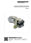
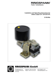
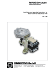
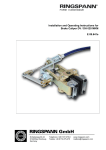
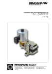
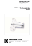
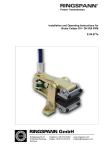
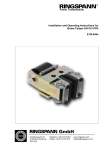
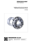
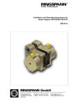
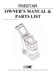
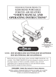
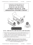
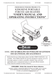
Power Transmission Installation and Operating Instructions for Brake Caliper DV / DH 030 FPM E 09.657e Schaberweg 30-34 61348 Bad Homburg Germany Telephone +49 6172 275-0 Telefax +49 6172 275-275 www.ringspann.com mailbox@ringspann.com Installation and Operating Instructions for Brake Caliper DV and DH 030 FPM spring activated - pneumatically released Issue: 06.06.2013 Version : 7 drawn: Su checked: Su E 09.657 e Pages: 11 Page: 2 IMPORTANT Please read these instructions carefully before installing and operating the product. Your particular attention is drawn to the notes on safety. These installation and operating instructions are valid on condition that the product meets the selection criteria for its proper use. Selection and design of the product is not the subject of these installation and operating instructions. Disregarding or misinterpreting these installation and operating instructions invalidates any product liability or warranty by RINGSPANN; the same applies if the product is taken apart or changed. These installation and operating instructions should be kept in a safe place and should accompany the product if it is passed on to others -either on its own or as part of a machine- to make it accessible to the user. SAFETY NOTICE Installation and operation of this product should only be carried out by skilled personnel. Repairs may only be carried out by the manufacturer or accredited RINGSPANN agents. If a malfunction is indicated, the product or the machine into which it is installed, should be stopped immediately and either RINGSPANN or an accredited RINGSPANN agent should be informed. Switch off the power supply before commencing work on electrical components. Rotating machine elements must be protected by the purchaser to prevent accidental contact. Supplies abroad are subject to the safety laws prevailing in those countries. Installation and Operating Instructions for Brake Caliper DV and DH 030 FPM spring activated - pneumatically released Issue: 06.06.2013 Version : 7 drawn: Su Contents 1. General information 2. Configuration and function 2.1 Safety instructions 3. Drawing and parts list 4. Condition on delivery 5. Installing the RINGSPANN brake caliper 5.1 Installation 5.2 Compressed air connection 5.3 Brake caliper adjustment 5.4 Running-in procedure 5.5 Electrical connection for the inductive proximity switch 6. Maintenance 6.1 General maintenance 6.2 Checking / adjusting braking force 6.3 Checking brake pad wear 7. Replacing wearing parts 7.1 Brake pads 7.2 Brake chamber checked: Su E 09.657 e Pages: 11 Page: 3 Installation and Operating Instructions for Brake Caliper DV and DH 030 FPM spring activated - pneumatically released Issue: 06.06.2013 1. Version : 7 drawn: Su checked: Su E 09.657 e Pages: 11 Page: 4 General information These installation and operating instructions apply to: the DV 030 FPM, brake caliper mounted parallel to the brake disc (frame construction V see Fig. 3.1 in Section 3); brake chamber mounted on the right. the DH 030 FPM, brake caliper mounted at a right angle to the brake disc (frame construction H see Fig. 3.2 in Section 3); brake chamber mounted on the right. the DV 30 FPM and DH 30 FPM with left mounted brake chamber for installation on an brake disc with a thickness of 25.0 or 12.5 mm. (28.6 mm) various types of brake-pads, e.g. with wear alarm cable, increased glide speed, double friction surface or other special brake pad materials. Versions without the additional rubber protection cap with cable tie. the version with adapter for encoder mounting, without inductive proximity switches. the version for mounting on a 40 or 30 mm thick clamping rail. the version with a 050 or 060 brake chamber. An identification plate with a 16-digit part number is affixed to the calliper. The precise design of the brake calliper is defined by this part number only. Please consult the drawings in each section when using this instructions. Danger to life and limb! It is essential to secure the entire drive train against inadvertent starts during brake installation and maintenance. Rotating components can cause severe injuries. Therefore, rotating components (e.g. brake disc) must be secured by the operator to prevent accidental contact. 2. Configuration and function The brake caliper is used as a stopping and parking brake. Braking force is generated by a spring in the brake chamber (5). It is released (opened) pneumatically with compressed air. Brake pad (3) wear decreases holding/braking force, as spring pressure is reduced. When brake pad wear occurs in the course of normal operation, brake pads must be inspected and adjusted as described in Section 6.2 and 6.1. Rotating parts must be secured by the user against inadvertent contact (e.g. brake disc). 2.1 Safety instruction The brake chamber (5, see parts list) may be dismantled by the manufacturer only. Warning! Danger of injury! Brake chambers are equipped with high-pressure pre-tensed springs. When the safety ring (9) is loosened or removed is spring pressure tension is relieve abruptly. Installation and Operating Instructions for Brake Caliper DV and DH 030 FPM spring activated - pneumatically released Issue: 06.06.2013 3. Version : 7 drawn: Su checked: Su E 09.657 e Pages: 11 Page: 5 Drawing and parts list Brake caliper Type DV 030 Brake caliper Type DH 030 Fig. 3.1 Fig. 3.2 Parts list: Part 5 Nomenclature Quantity Part number Brake chamber D30FPM 1 3514-100103-000000 Brake chamber D30FPM-50 1 3514-100115-000000 Brake chamber D30FPM-60 1 3514-100120-000000 Standard brake pad for brake calipers:: 4457-301616-000000 4457-901145-000000 4457-300643-000000 4457-300642-000000 4457-301648-000000 4457-301649-000000 2 2472-005013-A00112* Brake pad from BK 8006 for brake caliper: 4457-301621-000000 2 2472-005013-A00109* 3 *) Part number for 1 pad 4. Condition on delivery The brake calliper is delivered with a clamping gap of approx. 8.00 mm or 19.0 mm between the brake pads. Under air pressure DV(H) 030 FPM-050 (4,2 bar) and DV(H) 030 FPM-060 (5,5 bar), Installation and Operating Instructions for Brake Caliper DV and DH 030 FPM spring activated - pneumatically released Issue: 06.06.2013 Version : 7 drawn: Su checked: Su E 09.657 e Pages: 11 Page: 6 the brake caliper opens to the pre-defined clamping gap of 26.0 or 13.5 mm (Example:. Brake disc thickness 25.0 mm plus 0.5 mm gap on each side between the brake disc and the brake pads = 26.0 mm). 5. Installing the RINGSPANN brake caliper Before installing the brake, the brake disc must be cleaned with alcohol, e.g. ethyl or isopropyl alcohol, or a water-based surfactant solution (soapy water, etc.) and then rubbed dry with a clean cloth. When cleaning the brake disc with a thinner, acetone or a brake cleaning agent, it is important to ensure that neither these cleaners nor any cleaner residues come in contact with the brake pads. This is especially important in the case of brakes used only as parking brakes, as no dynamic braking operations take place during which thinner residues would be rubbed off the brake disc. Caution! Oil and rust-proofing-agent residues reduced friction coefficient and thus diminish transmissible braking torque substantially! Before installing on the brake disc, the brake caliper must be released (opened). This is possible by: once the compressed air supply has been connected (see Section 5.2) by turning the push rod unit (2) back to a distance of approx. 7 mm from the face of the piston (7); see detail in Fig. 3.1, Section 3 Caution! When the plunger unit is turned back, all procedures described in Sections 5.1 through 5.4 must be performed to ensure full brake caliper function after installation! 5.1 Installation The brake calliper should be mounted to stabile, vibration-free machine components in order to ensure noise-free, non-screech. During installation, it is essential to ensure that brake pads are centred and in full contact with the brake disc (the midlines of the brake arm must point to the midpoint of the brake disc.). Maximum permissible lateral brake disc wobble is 0.2 mm. Greater wobble may cause rattling and shaking of the brake unit. The brake caliper is using: 4 bolts M12 (Type DV 030 ) or. 3 bolts M12 (Type DH 030) the strength class 8.8. attached in the machine part. Installation and Operating Instructions for Brake Caliper DV and DH 030 FPM spring activated - pneumatically released Issue: 06.06.2013 Version : 7 drawn: Su checked: Su E 09.657 e Pages: 11 Page: 7 5.2 Compressed air connection The system requires pressure of at least 4.2 bar at the brake chamber size 050 and 5.5 bar at the brake chamber size 060; maximum permissible pressure is 8 bar. A flexible hose connection is required. Please use hoses with a diameter of 6 mm. Hose pressure must be at least 7 bar (preferably 12 bar) with a temperature range of approx. - 20°C to + 80°C. Air hoses are connected (at 1, Fig. 3.1, Section 3) to the brake chamber with a G 1/4 " fitting (Whitworth threaded pipe, DIN ISO 228-1). Compressed air must be filtered to remove all dirt, pipe chips, rust and condensation. Purified air must then be enriched with a fine oil mist injected by a standard, commercially available airpreparation unit. The quantity of oil added depends on the nominal air flow rate in l/min and is specified by the manufacturer of the air-preparation unit. The following types of oil are recommended for air-preparation units: Suitable types of oil Viscosity at 20° C (mm²/s) Avia Avilub RSL 3 BP Energol HLP 40 ESSO Spinesso 34 Shell Tellus Öl C 10 Mobil VAC HLP 9 34 27 23 22 25,2 Maximum air consumption per braking operations is approx. 55 cm³ . 5.3 Brake caliper adjustment Caution! The brake or holding torque must be adjusted before to commissioning. Pressurize the brake chamber with the respective permissible minimum air pressure. Please note: Actual operating pressure must be equal to or greater than this pressure setting, as otherwise the brake calliper will not open completely during normal operation and brake pads may rub against the brake disc. Turn both threaded pins M10x40 DIN EN ISO 4026 (8) in the caliper arms counter-clockwise, approx. 2 full turns. Turn the push rod unit (2) clockwise with an SW 10 Allen key until the push rod (4) makes contact with the lever. Stellen Adjusting a small gap (from 0.2 to 0.4 mm) between the two brake pads and the brake disc, but not the friction pads rub against the disc. This is best done by pressing one brake pad against the brake disc and setting the total gap on the other side with the aid of a feeler gauge. Installation and Operating Instructions for Brake Caliper DV and DH 030 FPM spring activated - pneumatically released Issue: 06.06.2013 Version : 7 drawn: Su checked: Su E 09.657 e Pages: 11 Page: 8 Please note: The minimum adjustable gap depending on the existing lateral wobble of the disc. The smaller the gap, the larger the wear reserve, i.e. the distance to the point at which the brake pads must be readjusted. Depending upon the positions of the brake calliper and the brake disc axle, the laterally mounted brake chamber may cause tipping resulting in an unequal gap between the brake pads and the brake disc. In extreme cases, one brake pad may come to rest against the brake disc, while the total gap shifts to the other side of the disc., which in turn would result in constant rubbing of this brake pad against the disc during operation. The gap can be adjusted (distributed equally) with the aid of the threaded pin (8). Determine where the gap between the brake pad (caliper lever) and the disc is largest. Then turn the threaded pin (8) on that side clockwise until the gap is equal on both sides. Caution! It is important to ensure that the brake pads (3) do not rub against the brake disc when the brake is released (open). When pressure is released from the brake chamber is now the full braking torque (holding torque) available. 5.4 Running-in procedure Optimum braking effect is achieved only when both brake pads (3) are in full contact with the brake disc and the brake pads have attained a temperature of approx. 200°C. A repeated, short braking at the rotating disc is therefore necessary. Caution! If running-in is not performed, the braking forces cited in our catalogue no. 46 cannot be achieved. Reductions of up to 50% are possible. Please note: If a running-in at fully vented brake caliper is not possible (it acts full spring force), you can braking force by a low air pressure (1...4 bar) reduce. 5.5 Electrical connection for the inductive proximity switch A DC 12V02PSLK inductive proximity switcher manufactured by DIEL is installed: Switching function Operating voltage Voltage drop Temp. range Connection : PNP (closer) : 10....35 V DC : < or = 1.5 V : -25 to +80°C : 2 m PVC cable Circuit diagram, PNP technology Switching distance : 2 mm flush-mountable Max. op. current : 0...200 mA Polarity reversal-resistant : yes Safety class : IP 67 Housing : M12x1 V4A Installation and Operating Instructions for Brake Caliper DV and DH 030 FPM spring activated - pneumatically released Issue: 06.06.2013 Version : 7 drawn: Su E 09.657 e checked: Su Pages: 11 Page: 9 The proximity switch is positioned in such a way that it is closed by the reference plate when spring pressure is exerted (air pressure > 5 bar or > 4.2 bar). When air pressure is released, the brake closes and the reference plate moves out of the range of the switch (the switch is no longer closed). Procedure for installing or replacing the proximity switch: The following instructions apply to the proximity switch listed above, with 2-mm switching distance. To prevent the connecting cable from twisting, mount the proximity switch before making the electrical connection. Apply air pressure (5.5 – 6 bar) to the brake cahmber. The brake caliper opens, the reference plate is pressed into the end position. Measure gap “a”. Mount the proximity switch to the adapter with a length of “a-1mm” (Fig. 5.1) and secure the switch in place with a counter-nut. Screw the adapter with the washer into the brake chamber and tighten the adapter firmly. Test for proper function by activating the brake caliper several times in succession. When the brake caliper is opened (air pressure is applied), the proximity switch must be closed and current can flow through Example of an optical display: Fig. 5.1 A monostable switch relay is required. Contact 0 - 1 : relay in passive state (rest) IL = 0 mA Braking force is applied - Lamp A glows. Contact 0 - 2 : relay in active state (inductive proximity switch closed) IL > 0 mA No braking force is exerted - Lamp B glows. Fig. 5.2 Installation and Operating Instructions for Brake Caliper DV and DH 030 FPM spring activated - pneumatically released Issue: 06.06.2013 6. Version : 7 drawn: Su checked: Su E 09.657 e Pages: 11 Page: 10 Maintenance Maintenance should be performed on the brake caliper at intervals of 4 to 12 weeks, depending upon the frequency and duration of operation. 6.1 General maintenance Check both brake levers for easily of movement. Clean all bearings and glide points Lubricate all bearing and glide points. Check to ensure that the brake pads do not rub against the brake disc when the brake caliper is open, i.e. hat the gap is uniform on both sides; optionally adjust the air gap, as described under 5.3. Caution! Brake pads must not be come in contact with lubricants. Check for fixed bolt / screw connections: Brake caliper to machine component Brake chamber to caliper-lever arm Brake pads to caliper-lever arm Check the following for proper seal / leaks: Brake chamber Hose connection (leaks can be detected quickly and easily using e.g. "Güpoflex LECKSUCHER", manufactured by: GÜPO GmbH, 77694 Kehl, Telephone 07851/4044-45, or equivalent products). 6.2 Checking / adjusting braking force Check the braking torque and/or spring preload. When the brake caliper is closed, on the brake chamber measure how far the piston (7), shown in Fig. 3.1, Section 3, against the brake chamber cover projecting. Caution! If brake pads are worn, brake caliper spring relaxation increases when the brake is closed and the distance to which the piston (7, Measure “V”) protrudes (Fig. 3.1) decreases. This reduces the braking force. When this distance reaches 13.0 mm, at the latest, braking torque adjustment must be performed as described in Section 5.3. Installation and Operating Instructions for Brake Caliper DV and DH 030 FPM spring activated - pneumatically released Issue: 06.06.2013 Version : 7 drawn: Su checked: Su E 09.657 e Pages: 11 Page: 11 6.3 Checking brake pad wear Brake pad material must have a thickness of at least 6 mm (from the top surface of the brake pad to the top surface of the steel mounting plate). Brake pads or brake linings (Pos. 3) must always be replaced in pairs. 7. Replacing wearing parts 7.1 Brake pads Ensure that the mass held by the brake is secured against shifting or movement, as the brake must be released (opened) in order to replace the brake pads. The brake chamber with air pressurize; the brake opens. Turn back the push rod unit (2) return to the point at which a gap of approx. 7 mm from the face of the piston (7) remains (see detail Fig. 3.1, Section 3). Then turn the threaded pin (8) used as a stop so far return until the brake pads can be replaced easily. Fixed spanner or ring spanner SW13 are used to tighten connect and solve bolts/screws. Following replacement of the brake pads, the braking torque and gap must be readjusted as described in Section 5.3. Danger to life and limb! Brake pads may be replaced only when the equipment system and/or the working machine is at a complete standstill! 7.2 Brake chamber The brake chamber is defective when the push rod (4) does not move when pressure is applied and released or when air escapes from the brake chamber. Inspection and repair of the brake chamber must be performed by the manufacturer. Caution! Danger opf injury! Brake chambers are equipped with high-pressure pre-tensed springs. When the safety ring (9) is loosened or removed is spring pressure tension is relieve abruptly.