1
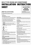
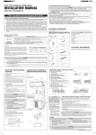
AIR CONDITIONER
OUTDOOR UNIT
Solo para personal autorizado.
MANUALE D'INSTALLAZIONE
Ad uso esclusivo del personale autorizzato.
ΕΓΧΕΙΡΙΔΙΟ ΕΓΚΑΤΑΣΤΑΣΗΣ
Για εξουσιοδοτημένο προσωπικό σέρβις.
MANUAL DE INSTALAÇÃO
Apenas para técnicos autorizados.
РУКОВОДСТВО ПО УСТАНОВКЕ
Для уполномоченного персонала.
KURULUM KILAVUZU
Yetkili servis personeli içindir.
Deutsch
Français
Español
MANUAL DE INSTALACIÓN
Italiano
Pour le personnel agréé uniquement.
EλληvIkά
MANUEL D'INSTALLATION
Português
Nur für autorisiertes Personal.
Русский
INSTALLATIONSANLEITUNG
Türkçe
INSTALLATION MANUAL
For authorized service personnel only.
English
INSTALLATION MANUAL
PART NO. 9374995202-02
9374995202-02_IM.indb 1
28/11/2555 10:28:08
AIR CONDITIONER
OUTDOOR UNIT
2.2. Special tools for R410A
Tool name
INSTALLATION MANUAL
9374995202-02
Gauge manifold
Contents
1.
SAFETY PRECAUTIONS .......................................................................................... 1
2.
ABOUT THE UNIT ..................................................................................................... 1
3.
SELECTING THE MOUNTING POSITION ............................................................... 2
4.
INSTALLATION DIAGRAM ........................................................................................ 2
5.
INSTALLATION ......................................................................................................... 3
6.
PUMP DOWN ............................................................................................................ 6
Contents of change
Pressure is high and cannot be measured with a conventional (R22) gauge. To prevent erroneous mixing of other
refrigerants, the diameter of each port has been changed.
It is recommended the gauge with seals -0.1 to 5.3 MPa
(-1 to 53 bar) for high pressure. -0.1 to 3.8 MPa (-1 to
38 bar) for low pressure.
Charge hose
To increase pressure resistance, the hose material and base
size were changed.
Vacuum pump
A conventional vacuum pump can be used by installing a
vacuum pump adapter.
Gas leakage detector
Special gas leakage detector for HFC refrigerant R410A.
Copper pipes
It is necessary to use seamless copper pipes and it is desirable that the amount of residual
oil is less than 40 mg/10 m. Do not use copper pipes having a collapsed, deformed or
discolored portion (especially on the interior surface). Otherwise, the expansion value or
capillary tube may become blocked with contaminants.
As an air conditioner using R410A incurs pressure higher than when using R22, it is
necessary to choose adequate materials.
Thicknesses of copper pipes used with R410A are as shown in Table1. Never use copper
pipes thinner than 0.8 mm even when it is available on the market.
1. SAFETY PRECAUTIONS
1.1. For authorized service personnel only
CONNECTION PIPE REQUIREMENT
WARNING
This mark indicates procedures which, if improperly performed, might lead to the death or serious injury of the user.
For the room air conditioner to operate satisfactory, install it as outlined in this installation manual.
Connect the indoor unit and outdoor unit with the air conditioner piping and cables
available standards parts. This installation manual describes the correct connections
using the standard accessories and the parts specified in this installation manual.
Have installation work done by authorized service personnel only.
Do not turn on the power until all installation work is complete.
This mark indicates procedures which, if improperly
performed, might possibly result in personal harm to the user,
or damage to property.
When installing pipes shorter than 3 m, sound of the outdoor unit will be transferred to
the indoor unit, which will cause large operating sound or some abnormal sound.
This installation manual describes how to install the outdoor unit only.
To install the indoor unit, refer to the installation manual included with the indoor unit.
• Be careful not to scratch the air conditioner when handling it.
• After installation, explain correct operation to the customer, using the operating manual.
• Let the customer keep this installation manual because it is used when the air conditioner is serviced or moved.
• The maximum lengths of this product are shown in the following table.
If the units are further apart than this, correct operation cannot be guaranteed.
Model
type
30L
Pipe diameter
Liquid
Gas
9.52 mm 15.88 mm
(3/8 in.) (5/8 in.)
Piping length
Outer diameter
Thickness
3/8 in
5/8 in
9.52 mm
15.88 mm
0.8 mm
1.0 mm
WARNING
Do not use the existing (for R22) piping and flare nuts.
If the existing materials are used, the pressure inside the refrigerant cycle will rise and
cause failure, injury, etc. (Use the special R410A materials.)
Do not use this equipment with air or any other unspecified refrigerant in the refrigerant
lines.
Excess pressure can cause a rupture.
Do not use an extension cable.
CAUTION
Nominal diameter
MAX.
MIN.
Max. height difference
(Indoor unit to outdoor unit)
50 m
5m
30 m
2. ABOUT THE UNIT
2.1. Precautions for using R410A refrigerant
The basic installation work procedures are the same as conventional refrigerant (R22)
models.
However, pay careful attention to the following points:
Since the working pressure is 1.6 times higher than that of conventional refrigerant
(R22) models, some of the piping and installation and service tools are special. (See
the table below.)
Especially, when replacing a conventional refrigerant (R22) model with a new refrigerant
R410A model, always replace the conventional piping and flare nuts with the R410A piping
and flare nuts.
Models that use refrigerant R410A have a different charging port thread diameter to prevent erroneous charging with conventional refrigerant (R22) and for safety. Therefore,
check beforehand. [The charging port thread diameter for R410A is 1/2 inch.]
During installation, make sure that the refrigerant pipe is attached firmly before you run
the compressor.
Do not operate the compressor under the condition of refrigerant piping not attached
properly with 2-way or 3-way valve open. This may cause abnormal pressure in the
refrigeration cycle that leads to rupture and even injury.
When installing and relocating the air conditioner, do not mix gases other than the
specified refrigerant (R410A) to enter the refrigerant cycle.
If air or other gas enters the refrigerant cycle, the pressure inside the cycle will rise to
an abnormally high value and cause rupture, injury, etc.
2.3. Power
• The rated voltage
230V
AC 50Hz.
WARNING
The rated voltage of this product is 230 V AC 50 Hz.
Before turning on the power, check if the voltage is within the 220 V -10 % to 240 V
+10 % range.
Always use a special branch circuit and install a special receptacle to supply power to
the room air conditioner.
Use a circuit breaker and receptacle matched to the capacity of the air conditioner.
Do not extend the power cable.
Perform wiring work in accordance with standards so that the air conditioner can be
operated safely and positively.
Install a leakage circuit breaker in accordance with the related laws and regulations and
electric company standards.
The circuit breaker is installed in the permanent wiring. Always use a circuit that can trip
all the poles of the wiring and has an isolation distance of at least 3 mm between the
contacts of each pole.
CAUTION
Be more careful that foreign matter (oil, water, etc.) does not enter the piping than with
refrigerant (R22) models. Also, when storing the piping, securely seal the opening by
pinching, taping, etc.
The power source capacity must be the sum of the air conditioner current and the current of other electrical appliances. When the current contracted capacity is insufficient,
change the contracted capacity.
When charging the refrigerant, take into account the slight change in the composition of
the gas and liquid phases. And always charge from the liquid phase where refrigerant
composition is stable.
When the voltage is low and the air conditioner is difficult to start, contact the power
company the voltage raised.
En-1
9374995202-02_IM.indb 1
28/11/2555 10:28:09
2.4. Electric requirement
3. SELECTING THE MOUNTING POSITION
• Electric wire size and fuse capacity:
• Decide the mounting position with the customer as follows:
MAX.
MIN.
MAX.
MIN.
Power supply cable (mm2)
Connection cable (mm2)
4.0
3.5
2.5
1.5
Fuse capacity (A)
• Do not set to a place where there is oily smoke, oil is used in the factory, the unit can
contact sea breeze, sulfide gases will be generated in the hot spring area, corrosive
gases will be generated, animal may urine on the unit and ammonia will be generated
and a dusty place.
30
3.1. Outdoor unit
• Use conformed cable with Type245 IEC57.
• Install all electrical works in accordance to the national standard.
• Install the disconnect device with a contact gap of at least 3 mm in all poles nearby the
units. (Both indoor unit and outdoor unit)
• Install the circuit breaker nearby the units.
2.5. Operating range
Outdoor
Temperature
Cooling / Dry Mode
About -10 to 46 °C
Heating Mode
About -15 to 24 °C
2.6. Additional charge
Refrigerant suitable for a piping length of 20 m is charged in the outdoor unit at the factory.
When the piping is longer than 20 m, additional charging is necessary.
For the additional amount, see the table below.
Piping length
Model type
30L
(1) If possible, do not install the unit where it will be exposed to direct sunlight.
(If necessary, Install a blind that does not interfere with the air flow.)
(2) Do not install the unit where a strong wind blows or where it is very dusty.
(3) Do not install the unit where people pass.
(4) Take you neighbors into consideration so that they are not disturbed by air blowing
into their windows or by noise.
(5) Provide the space shown in figure so that the airflow is not blocked. Also for efficient
operation, leave open three of the four directions front, rear, and both sides.
(6) Install the outdoor unit in a location which can withstand the weight of the unit and
vibration, and which can install horizontally.
(7) Provide the indicated space to ensure good airflow.
(8) During heating operation, drain water flows from the outdoor unit.
Therefore, install the outdoor unit in a place where the drain water flow will not be
obstructed. (Reverse cycle model only)
(9) Install the outdoor unit in a place where it will be free from being dirty or getting wet
by rain as much as possible.
(10) Install the unit where connection to the indoor unit is easy.
WARNING
20 m
30 m
40 m
50 m
Rate
None
400 g
800 g
1200 g
40 g/m
Install at a place that can withstand the weight of the outdoor units and install positively
so that the units will not topple or fall.
CAUTION
CAUTION
When moving and installing the air conditioner, do not mix gas other than the specified
refrigerant R410A inside the refrigerant cycle.
When charging the refrigerant R410A, always use an electronic balance for refrigerant
charging (to measure the refrigerant by weight).
When charging the refrigerant, take into account the slight change in the composition
of the gas and liquid phases, and always charge from the liquid phase side whose
composition is stable.
Gas
Do not install where there is the danger of combustible gas leakage.
Do not install near heat sources.
If children under 10 years old may approach the unit, take preventive measures so that
they cannot reach the unit.
4. INSTALLATION DIAGRAM
[OUTDOOR UNIT]
• Do not directly install it on the ground, otherwise it will cause failure.
R410A
Liquid
Add refrigerant from the charging valve after the completion of the work.
If the units are further apart than the maximum pipe length, correct operation cannot be
guaranteed.
2.7. Accessories
Name and Shape
Q’ty
Insulation (seal)
Name and Shape
Q’ty
Installation manual
1
1
5 cm or more
Drain cap
Drain pipe
1
CAUTION
2
In the area with heavy snowfall, if the intake and outlet of outdoor unit is blocked with snow,
it might become difficult to get warm and it is likely to cause of the breakdown. Please
construct a canopy and a pedestal or place the unit on a high stand (local configured).
One set of following parts are necessary in installation of this air conditioner.
Name
Connection pipe assembly
Connection cable
Wall pipe
Decorative tape
Vinyl tape
Wall cap
Saddle
Drain hose
Tapping screws
Sealant
M10 bolt, nut
En-2
9374995202-02_IM.indb 2
28/11/2555 10:28:09
(3) Since the drain water flows out of the outdoor unit during heating operation, install
the drain pipe and connect it to a commercial 16 mm hose. When installing the drain
pipe, plug all the holes other than the drain pipe mounting hole in the bottom of the
outdoor unit with putty so there is no water leakage. (Reverse cycle model only)
When there are obstacles at the back side.
370 mm
Drain cap mounting holes
Bottom
side
10 cm
or more
650 mm
When there are obstacles at the back and front sides.
Drain pipe mounting hole
4-ø12 hole
Base
Drain pipe
10 cm
or more
60 cm or more
CAUTION
When the outdoor temperature is 0 °C or less, do not use the accessory drain pipe
and drain cap. If the drain pipe and drain cap are used, the drain water in the pipe may
freeze in extremely cold weather. (Reverse cycle model only)
When there are obstacles at the back, side(s), and top.
5.2. Outdoor unit wiring
60 cm
or more
WARNING
Use crimp-type terminals and tighten the terminal screws to the specified torques, otherwise,
abnormal overheating may be produced and possibly cause heavy damage inside the unit.
Match the terminal block numbers and connection cable colors with those of the outdoor
unit. Erroneous wiring may cause burning of the electric parts.
Connect the connection cable firmly to the terminal block. Imperfect installation may
cause a fire.
10 cm
or more
30 cm
or more
25 cm or more
(Service space)
When there are obstacles at the back side with the installation of more than one unit.
Always fasten the outside covering of the connection cable with the cable clamp.
(If the insulator is chafed, electric leakage may occur.)
Securely earth the power cable plug.
Do not use the earth screw for an external connector. Only use for interconnection
between two units.
HOW TO CONNECT THE WIRE TO THE TERMINALS
(1) Use crimp-type terminals with insulating sleeves as shown in the figure below to
connect to the terminal block.
(2) Securely crimp the crimp-type terminals to the wires using an appropriate tool so that
the wires do not come loose.
(3) Use the specified wires, connect them securely, and fasten them so that there is no
stress placed on the terminals.
(4) Use an appropriate screwdriver to tighten the terminal screws. Do not use a
screwdriver that is too small, otherwise, the screw heads may be damaged and
prevent the screws from being properly tightened.
25 cm
or more
30 cm
or more
25 cm
or more
(5) Do not tighten the terminal screws too much, otherwise, the screws may break.
(6) See the table below for the terminal screw tightening torques.
Crimp-type terminal
Strip
10 mm
5. INSTALLATION
Sleeve
5.1. Installation
(1) Outdoor unit to be fasten with bolts at the four places indicated by the arrows without
fail.
(2) Fix securely with bolts on a solid block. (Use 4 sets of commercially available M10
bolt, nut and washer.)
Bolt
Nut
Screw with
special washer
Wire
Crimp-type
terminal
Terminal board
Block
Terminal block
Screw with
special washer
Crimp-type
terminal
Wire
En-3
9374995202-02_IM.indb 3
28/11/2555 10:28:09
Tightening torque
M4 screw
1.2 to 1.8 N·m (12 to 18 kgf·cm)
M5 screw
2.0 to 3.0 N·m (20 to 30 kgf·cm)
1. CONNECTION DIAGRAMS
Connection cable
Power supply
EARTH
Power supply cable
EARTH
3
2
1
N
L
3
2
1
Indoor unit
side terminal
Outdoor unit
side terminal
Power line
Indoor
unit
(5) Power supply cable and connection cable should be fixed with cable clip as shown in
the figure.
Fill in a gap at the entrance of the cables with insulation (seal).
EARTH
Power supply cable and connection cable
2. CONNECTION CABLE PREPARATION
Keep the earth wire longer than the other wires.
30 mm
or more
Cable clip
Power supply cable
or connection cable
Earth wire
Insulation
(Seal)
40 mm
or more
CAUTION
CAUTION
When connecting the power supply cable, make sure that the phase of the power
supply matches with the phase of the terminal board. If the phases do not match, the
compressor will rotate in reverse and will not be able to compress.
Fix cables so that cables do not make contact with the pipes (especially on high pressure side).
Do not make power supply cable and connection cable come in contact with valve (Gas).
Power supply cable
and connection cable
Gap
(1) Service cover removal
• Remove the two mounting screws.
• Remove the service cover by pushing downwards.
Valve
(Gas)
Hook (3 places)
Direction of the
service cover
removal
(6) Put the service cover and valve cover back after completion of the work.
5.3. Connecting the piping
Service cover
(2) Valve cover removal.
• Remove the one mounting screw.
• Remove the valve cover by sliding upward.
Valve cover
FLARING
(1) Cut the connection pipe to the necessary length with a pipe cutter.
(2) Hold the pipe downward so that cuttings will not enter the pipe and remove the
burrs.
(3) Insert the flare nut onto the pipe and flare the pipe with a flaring tool.
Insert the flare nut (always use the flare nut attached to the indoor and outdoor units
respectively) onto the pipe and perform the flare processing with a flare tool.
Use the special R410A flare tool, or the conventional (for R22) flare tool.
When using the conventional flare tool, always use an allowance adjustment gauge and
secure the A dimension shown in table 2.
Check if [L] is flared uniformly and
is not cracked or scratched.
Hook (4 places)
Die
(3) Connect the power supply cable and the connection cable to terminal.
(4) Fasten the power supply cable and connection cable with cable clamp.
A
Control box
Pipe
Terminal blocks
Pipe outside
diameter
Cable clamp
Firmly secure
cable clamp so
wire terminations
will not receive
external stress.
Cable clamp
ø 9.52 mm (3/8")
ø 15.88 mm (5/8")
Flaring tool for
R410A, clutch type
0 to 0.5
0 to 0.5
A (mm)
Conventional (R22) Flaring tool
Clutch type
Wing nut type
1.0 to 1.5
1.5 to 2.0
1.0 to 1.5
1.5 to 2.0
BENDING PIPES
Use the specified
wire type and
connect it securely.
(1) When bending the pipe, be careful not to crush it.
(2) To prevent breaking of the pipe, avoid sharp bends.
Bend the pipe with a radius of curvature of 70 mm or over.
(3) If the copper pipe is bend the pipe or pulled to often, it will become stiff. Do not
bend the pipes more than three times at one place.
En-4
9374995202-02_IM.indb 4
28/11/2555 10:28:09
Connection pipe
CONNECTION PIPES
Outdoor unit
(1) Detach the caps and plugs from the pipes.
Blank cap
Outdoor unit
Hexagon wrench
CAUTION
Be sure to apply the pipe against the port on the indoor unit and the outdoor unit correctly. If the centering is improper, the flare nut cannot be tightened smoothly. If the flare
nut is forced to turn, the threads will be damaged.
Use a 4 mm
hexagon wrench.
3-way valve
Service hose
with valve core
Charging port
Do not remove the flare nut from the indoor unit pipe until immediately before connecting the connection pipe.
Cap
(2) Centering the pipe against port on the outdoor unit, turn the flare nut with your hand.
To prevent gas leakage,
coat the flare surface with
alkylbenzene oil (HAB).
Do not use mineral oil.
(3) Tighten the flare nut of the connection pipe at the outdoor unit valve connector.
CAUTION
Gauge manifold
Lo
Use a clean gauge
manifold and charging
hose for R410A exclusively
Hi
Vacuum pump
3-way valve
(Liquid)
Flare nut
Connection
pipe (Liquid)
3-way valve
(Gas)
Flare nut
Connection pipe
(Gas)
Service hose
(4) When the flare nut is tightened properly by your hand, use a torque wrench to finally
tighten it.
Holding spanner
CAUTION
Do not purge the air with refrigerants, but use a vacuum pump to vacuum the installation!
There is no extra refrigerant in the outdoor unit for air purging!
Use a vacuum pump and gauge manifold and charging hose for R410A exclusively.
Using the same vacuum for different refrigerants may damage the vacuum pump or the unit.
Body side
90°
GAS LEAKAGE INSPECTION
CAUTION
Torque wrench
After connecting the piping, check the all joints for gas leakage with gas leak detector.
When inspecting gas leakage, always use the vacuum pump for pressure. Do not use
nitrogen gas.
CAUTION
Hold the torque wrench at its grip, keeping it in the right angle with the pipe, in order to
tighten the flare nut correctly.
Flare nut
9.52 mm (3/8 in.) dia.
15.88 mm (5/8 in.) dia.
Tightening torque
32 to 42 N·m (320 to 420 kgf·cm)
63 to 75 N·m (630 to 750 kgf·cm)
CAUTION
Fasten a flare nut with a torque wrench as instructed in this manual. If fastened too
tight, the flare nut may be broken after a long period of time and cause a leakage of
refrigerant.
CAUTION
Install insulation around both the gas and liquid pipes. Failure to do so may cause water
leaks.
Use insulation with heat resistance above 120 °C. (Reverse cycle model only)
In addition, if the humidity level at the installation location of the refrigerant piping is
expected to exceed 70%, install insulation around the refrigerant piping. If the expected
humidity level is 70-80%, use insulation that is 15 mm or thicker, and if the expected
humidity level exceeds 80%, use insulation that is 20 mm or thicker.
If insulation is used that is not as thick as specified, condensation may form on the
surface of the insulation.
In addition, use insulation with heat conductivity of 0.045 W/(m·K) or less (at 20 °C).
5.5. Test run
5.4. Air purge
• Perform test operation and check items.
Always use a vacuum pump to purge the air.
Refrigerant for purging the air is not charged in the outdoor unit at the factory.
(1) Remove the cap, and connect the gauge manifold and the vacuum pump to the
charging valve by the service hoses.
(2) Vacuum the indoor unit and the connection pipes until the pressure gauge indicates
-0.1 MPa (-76 cmHg).
(3) When -0.1 MPa (-76 cmHg) is reached, operate the vacuum pump for at least 60
minutes.
(4) Disconnect the service hoses and fit the cap to the charging valve to the specified
torque.
(5) Remove the blank caps, and fully open the spindles of the 2-way and 3-way valves
with a hexagon wrench [Torque: 6~7 N·m (60 to 70 kgf·cm)].
(6) Tighten the blank caps of the 2-way valve and 3-way valve to the specified torque.
9.52 mm (3/8 in.)
Blank cap
15.88 mm (5/8 in.)
Charging port cap
• For the test operation method, refer to the operating manual.
• The outdoor unit, may not operate, depending on the room temperature. In this case,
press the test run button on the remote controller while the air conditioner is running.
(Point the transmitter section of the remote controller toward the air conditioner and
press the test run button with the tip of a ball-point pen, etc.)
• To end test operation, press the remote controller START/STOP button.
(When the air conditioner is run by pressing the test run button, the OPERATION
indicator lamp and TIMER indicator lamp will simultaneously flash slowly.)
Transmitter section
Tightening torque
20 to 25 N·m (200 to 250 kgf·cm)
30 to 35 N·m (300 to 350 kgf·cm)
12.5 to 16 N·m (125 to 160 kgf·cm)
Test run button
En-5
9374995202-02_IM.indb 5
28/11/2555 10:28:10
OUTDOOR UNIT
(1) Is there any abnormal noise and vibration during operation?
(2) Will noise, wind, or drain water from the unit disturb the neighbors?
(3) Is there any gas leakage?
5.6. Customer guidance
Explain the followings to the customer in accordance with the operating manual:
(1) Starting and stopping method, operation switching, temperature adjustment, timer,
airflow switching, and other remote controller operations.
(2) Air filter removal and cleaning, and how to use the airflow direction louvers.
(3) Give the operating and installation manuals to the customer.
6. PUMP DOWN
6.1. Pump down
PUMP DOWN OPERATION (FORCED COOLING OPERATION)
To avoid discharging refrigerant into the atmosphere at the time of relocation or disposal,
recover refrigerant by doing the cooling operation or forced cooling operation according
to the following procedure. (When the cooling operation cannot start in winter, and so on,
start the forced cooling operation.).
(1) Do the air purging of the charge hose by connecting the charging hose of gauge
manifold to the charging port of 3-way valve and opening the low-pressure valve slightly.
(2) Close the valve stem of 2-way valve completely.
(3) Start the cooling operation or following forced cooling operation. Keep on pressing
the MANUAL AUTO button of the indoor unit for more than 10 seconds. The operation
indicator lamp and timer indicator lamp will begin to flash simultaneously during test
run. (The forced cooling operation cannot start if the MANUAL AUTO button is not kept
on pressing for more than 10 seconds.)
(4) Close the valve stem of 3-way valve when the reading on the compound pressure
gage becomes 0.05~0 Mpa (0.5~0 kg/cm2).
(5) Stop the operation.
• Press the START/STOP button of the remote control unit to stop the operation.
• Press the MANUAL AUTO button when stopping the operation from indoor unit side.
(It is not necessary to press on keeping for more than 10 seconds.)
CAUTION
During the pump-down operation, make sure that the compressor is turned off before
you remove the refrigerant piping.
Do not remove the connection pipe while the compressor is in operation with 2 way or
3 way valve open. This may cause abnormal pressure in the refrigeration cycle that
leads to rupture and even injury.
En-6
9374995202-02_IM.indb 6
28/11/2555 10:28:10