1
CFP 2/4/8 ZONE
ECONOMY
FIRE ALARM
CONTROL PANEL
installation &
maintenance
manual
Approved Document No. DFU7002030 Rev 1
CFP 2/4/8 ZONE ECONOMY FIRE ALARM PANEL
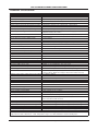
CONTENTS
Basic Overview and Key Features ......................................................................................................3
Important Notes ..................................................................................................................................4
The Fire Panel Enclosure ....................................................................................................................5
First Fix .................................................................................................................................................6
Cable types and limitations ..............................................................................................................................6
Mains wiring......................................................................................................................................................6
Planning the cable layout in the panel ..........................................................................................................6
Fixing the base to the wall ..............................................................................................................................7
Typical detector circuit wiring ........................................................................................................................7
Typical sounder circuit wiring ..........................................................................................................................8
Typical auxiliary input wiring ..........................................................................................................................8
Typical auxiliary output wiring ......................................................................................................................9
Second Fix ..........................................................................................................................................10
Connecting the panel ....................................................................................................................................10
Installing the Power Supply PCB ....................................................................................................................10
Connecting the Mains ....................................................................................................................................10
Connecting the standby batteries ................................................................................................................10
Installing the Main Control PCB ....................................................................................................................12
Connecting the detector and sounder circuits ............................................................................................13
Connecting the auxiliary inputs and outputs ..............................................................................................13
Programming the Panel ....................................................................................................................14
An overview of the panel’s controls ............................................................................................................14
Engineer controls ............................................................................................................................................14
Accessing the engineer controls ....................................................................................................................15
Programming zones into test and sounders function....................................................................................16
Fault Diagnosis ..................................................................................................................................17
Fault indications ............................................................................................................................................17
Zone faults ......................................................................................................................................................18
Power supply faults ........................................................................................................................................18
System faults ..................................................................................................................................................20
Sounder faults ................................................................................................................................................20
Remote output faults ....................................................................................................................................20
Maintenance ......................................................................................................................................20
Standby Battery Calculation Guide ..................................................................................................21
Technical Specification ......................................................................................................................22
Errors & Omissions Excepted. The manufacturer of this product operates a policy of continuous improvement and reserves the
right to alter product specifications at its discretion and without prior notice. All of the instructions covered in this manual have
been carefully checked prior to publication. However, no responsibility can be accepted by the manufacturer for any inaccuracies
or for any misinterpretation of an instruction or guidance note.
CFP ECONOMY FIRE ALARM PANEL INSTALLATION & MAINTENANCE MANUAL • Approved Document No. DFU7002030 Rev 1 • Page 2 of 22
CFP 2/4/8 ZONE ECONOMY FIRE ALARM PANEL
BASIC OVERVIEW AND KEY FEATURES
The fire alarm panel to which this manual relates is fully compliant with BS EN54 Parts 2 and 4.
Its features include the following:
•
Two, four or eight detector circuits (dependent on the model purchased);
•
Four conventional sounder circuits;
•
A flush or surface mountable plastic lid and enclosure;
•
A range of secure user functions (as detailed in the separate User Manual / Log Book) including the ability
to disable / enable a large number of system functions, as specified in EN54;
•
Keypad and keyswitch entry to access authorised user controls (access level two);
•
A wide range of engineering functions, including:
Zone test facility
Programming silenced sounders to resound, or not resound, when new zone in alarm
Fault diagnostic facilities
•
The following optional EN54 Part 2 features:
Output(s) to fire alarm devices {Clause 7.8}. Four conventional sounder circuits are provided to drive
external alarm sounders.
Test condition {Clause 10.0}. A zone test facility is provided.
•
The following features that are not required by EN54 Part 2:
Reset output (RESET) open collector output which provides a signal to reset any part of the fire alarm
system (if required) whilst the panel is being reset.
Remote output (REM) and Auxiliary fire output (AUX) open collector outputs which provide a signal to any
part of the fire alarm system that needs to be activated during a fire alarm condition.
Fault output (FAULT) open collector output (failsafe to open circuit).
Two (non-latching) auxiliary input connections; ‘class change’ and ‘alert’.
Please Note: CFP LPCB Approved and Alarmsense panels are also available which provide additional features such
as ‘zone delay facility’, ‘ancillary connections for repeaters’ and ‘on-board relays’. Contact your distributer for more
information.
CFP ECONOMY FIRE ALARM PANEL INSTALLATION & MAINTENANCE MANUAL • Approved Document No. DFU7002030 Rev 1 • Page 3 of 22
CFP 2/4/8 ZONE ECONOMY FIRE ALARM PANEL
IMPORTANT NOTES
This equipment must only be installed and maintained by a suitably skilled and technically
competent person.
THIS EQUIPMENT IS A PIECE OF CLASS 1 EQUIPMENT AND MUST BE EARTHED.
Items supplied with this panel
•
Installation & Maintenance Manual (i.e. this manual).
Explains how to install, commission and maintain the fire alarm control panel.
This manual must not be left accessible to the User.
•
User Manual / Log Book.
Gives detailed operational information, some of which will need to be referenced by the
installation engineer when setting up the panel. Sections of the user manual must be completed
by the engineer before system handover.
•
Torx key, for unfastening / securing the panel lid.
•
Electrical accessory pack, containing the following items:
8 x 0.47μF 50V capacitors
4 x 6K8 0.25W resistors
1 x Mains fuse
1 x battery connection kit
2 x nylon cable ties (for securing the batteries into the panel enclosure).
System design
Fire alarm system design is beyond the scope of this document. A basic understanding of fire alarm system
components and their use is assumed.
We strongly recommend that a suitably qualified and competent person is consulted in connection with the
design of the fire alarm system and that the system is commissioned and serviced in accordance with the laid
down specification and national standards. The fire officer concerned with the property should be contacted
at an early stage in case he / she has any special requirements.
We recommend you read BS 5839 Part 1: Fire detection and fire alarm systems for buildings - code of practice
for system design, installation, commissioning and maintenance, available at your local reference library or
from the BSI. Other national standards of installation should be referenced and adhered to where
applicable.
Equipment guarantee
This equipment is not guaranteed unless the complete system is installed and commissioned in accordance
with the laid down national standards by an approved and competent person or organisation.
This product has been manufactured in conformance with the requirements of all applicable
EU Council Directives.
CFP ECONOMY FIRE ALARM PANEL INSTALLATION & MAINTENANCE MANUAL • Approved Document No. DFU7002030 Rev 1 • Page 4 of 22
CFP 2/4/8 ZONE ECONOMY FIRE ALARM PANEL
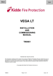
THE FIRE PANEL ENCLOSURE
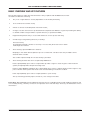
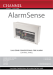
The panel is supplied with a plastic detachable lid, a plastic back box and a minimum of two separate PCBs.
The relative location of these PCBs is indicated in figure 1 below.
The panel can be surface or semi-flush mounted. It must be sited indoors in an area not subject to conditions
likely to affect its performance, e.g. damp, salt-air, water ingress, extremes of temperature, physical abuse,
etc. It should be sited at a height where it is easily accessible and in a prominent position within the building.
Ideally, the indicators on the front of the enclosure should be at eye level.
Typical locations for the panel are in the entrance foyer / hallway of a building at ground floor level (the
first and most obvious point of contact for emergency services) or a security office that is likely to be
permanently manned.
Removing the lid and base PCBs
To protect the electronics from damage and to expose the base mounting holes, the panel’s lid and PCBs
should be removed prior to first fix installation.
Anti-static handling guidelines
Please ensure that the following electro-static handling precautions are taken immediately
prior to handling the panel’s PCBs or any other static-sensitive components:
Before handling any static-sensitive items, operators should rid themselves of any personal electro-static
charge by momentarily touching any sound connection to safety earth, e.g. a radiator.
Always handle PCBs by their sides and avoid touching the legs of any components.
PCBs should be stored in a clean, dry place which is free from vibration, dust and excessive heat. Retaining
the PCBs in a suitable cardboard box will also guard them against mechanical damage.
Figure 1 : Location of the panel’s base PCBs and removal details
MAIN CONTROL PCB
PL1
push tab
and gently
lift cable
POWER SUPPLY PCB
Leave this end of the connector cable connected
to SK2 on the reverse of the Main Control PCB
1. Take the fire alarm panel out of its box and undo the two lid screws using the Torx key provided.
Remove the lid to expose the Main Control PCB (the Power supply PCB is located underneath).
2. Carefully remove the five retaining screws on the Main Control PCB and slide the PCB up and over the
mounting pillars, taking care not to damage any of the components.
3. Disconnect the telecoms-style connecting cable at PL1 on the Power Supply PCB, making sure that the
cable remains connected to the reverse of the Main Control PCB to prevent it being misplaced. Care
should be taken when detaching this connector to depress the locking tab to prevent damage.
4. Pull the Power Supply’s earth strap off the spade connector at the main chassis earth point.
5. Carefully remove the three retaining screws on the Power Supply PCB and slide the PCB up and over
the mounting pillars, again taking care not to damage any of the components.
CFP ECONOMY FIRE ALARM PANEL INSTALLATION & MAINTENANCE MANUAL • Approved Document No. DFU7002030 Rev 1 • Page 5 of 22
CFP 2/4/8 ZONE ECONOMY FIRE ALARM PANEL
FIRST FIX
All system wiring should be installed to meet BS 5839 Part 1 and BS 7671 (Wiring Regulations).
Other national standards of installation should be used where applicable.
Cable types and limitations
Consult {Clause 26} of BS 5839 Part 1: Fire detection and fire alarm systems for buildings - code of practice
for system design, installation, commissioning and maintenance, for detailed information on cables,
wiring and other interconnections.
To comply with EMC (Electro Magnetic Compatibility) regulations and to reduce the risk of electrical
interference in the system wiring, we recommend the use of fire-resistant screened cables throughout the
installation. Cables such as FP 200, Firetuff™, Firecel™ and MICC may be acceptable provided they are
properly terminated at the fire panel and meet national standards / system specification as applicable.
Correct cable glanding is essential and due regard should be made to any system specifications which
demand a certain cable type.
Mains wiring
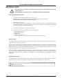
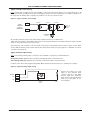
The requirement for the Mains supply to the fire panel is fixed wiring, using three core cable (no less than
1mm2 and no more than 2.5mm2) or a suitable three conductor system, fed from an isolating switched fused
spur, fused at 3A. This should be secure from unauthorised operation and be marked ‘FIRE ALARM: DO NOT
SWITCH OFF’. The Mains supply must be exclusive to the fire panel.
(As an alternative to a switched fused spur, a double pole isolating device may be used providing it meets
the appropriate national wiring regulations - see diagram below.)
≥ 1.0mm 2 < 2.5mm2
MAIN
DISTRIBUTION
BOARD
3A
FIRE
PANEL
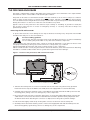
Planning the cable layout in the panel
The detector and sounder circuit cabling is classed as extra low voltage and should be segregated away
from Mains voltages. Careful planning is needed to ensure this, see figure 2 (below) for guidance. Drill
centre points are provided in the panel base to aid drilling tools. Cut out suitable holes in the panel using
a hole saw directed by a pilot bit in the centre of the hole saw. Always ensure that if a hole is cut out it is
filled with a good quality cable gland. Any unused holes must be securely blanked off.
Figure 2 : Location of centre points for hole removal
These four drill centre
points are for incoming
Mains cable only
Do not drill any additional holes
for cable entry in this shaded area.
This is where the PCBs and
backup batteries will be located.
Holes should be cut
out using a hole saw
with a pilot bit.
CFP ECONOMY FIRE ALARM PANEL INSTALLATION & MAINTENANCE MANUAL • Approved Document No. DFU7002030 Rev 1 • Page 6 of 22
CFP 2/4/8 ZONE ECONOMY FIRE ALARM PANEL
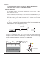
Fixing the base to the wall
Using the five mounting holes provided (see figure 3 below), fix the base securely onto / into the wall. The
mounting holes are suitable for use with No.8-10, or 4-5mm countersunk screws.
Assess the condition and construction of the wall and use a suitable screw fixing.
Any dust or swarf created during the fixing process must be kept out of the fire alarm panel and care must
be taken not to damage any wiring or components.
Figure 3 : Internal view of the back box with PCBs removed / side view for flush mounting
Fixing centres
339mm
75mm
includes 'dimples'
Fixing centres
170mm
Ensure no
fixing devices
are located
underneath the
Power Supply
PCB to avoid
compromising
electrical
safety
WALL
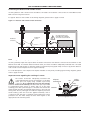
Typical detector circuit wiring
Depending on the model purchased, two, four, or eight detector circuit connections are available on the fire
alarm panel.
Refer to the specification on page 22 for the maximum number of devices that may be fitted to each circuit.
Note: The number of devices affects the standby time of the system, and this should be taken into
consideration when selecting the standby batteries. See page 21 for more information.
Figure 4 : Typical detector circuit wiring
PANEL
DETECTOR
CIRCUIT
TERMINALS
+
MANUAL
CALL
POINT
SMOKE
OR HEAT
DETECTOR
MANUAL
CALL
POINT
SMOKE
OR HEAT
DETECTOR
END OF LINE
CAPACITOR
–
DO NOT SPUR
(wiring not
monitored)
✗
Connect an end-of-line (EOL) capacitor (provided in the panel’s accessory pack) across the terminals of the
last device on each circuit to allow the wiring to be monitored.
Detector bases with integral continuity diodes must be used to ensure manual call points remain operational
when a detector head is removed from its base.
Manual call points with integral resistors must be used to prevent a short circuit fault occurring instead of a
fire condition when activated.
For more specific device wiring information, please refer to the manufacturers’ own instructions.
The wiring for each detector circuit should be connected to the relevant 5mm connector block on the Main
Control PCB and their screens terminated at the panel’s base earth post (see page 13 for detailed second fix
connection information).
CFP ECONOMY FIRE ALARM PANEL INSTALLATION & MAINTENANCE MANUAL • Approved Document No. DFU7002030 Rev 1 • Page 7 of 22
CFP 2/4/8 ZONE ECONOMY FIRE ALARM PANEL
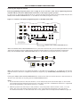
Typical sounder circuit wiring
Four conventional sounder circuits are available on the fire alarm panel. These can accommodate up to 40
polarised sounders (at 20mA) or 32 bells (at 25mA) per system. If a full complement of sounders or bells are to
be used, they should be split as equally as possible across all four sounder circuits.
Figure 5 : Typical sounder circuit wiring
PANEL
SOUNDER
CIRCUIT
TERMINALS
+
POLARISED
SOUNDER
+
POLARISED
SOUNDER
POLARISED
SOUNDER
+
+
END OF LINE
RESISTOR
(6k8 Ohm)
–
+
DO NOT SPUR
(wiring not
monitored)
✗
All sounders must be polarised as unpolarised sounders will show a sounder fault.
A 6k8 end-of-line resistor (provided in the panel’s accessory pack) must be connected at the end of each sounder
circuit to allow the wiring to be monitored.
The wiring for each sounder circuit should be connected to the relevant 5mm connector block on the Main
Control PCB and their screens terminated at the panel’s base earth post (see page 13 for detailed second fix
connection information).
Typical auxiliary input wiring
Two non-latching auxiliary input connections are available on the panel, as detailed below:
Alert Input (ALERT): Operates the sounders intermittently when connected to 0V.
Class Change Input (CC): Operates the sounders continuously when connected to 0V.
If either of the above are triggered, they WILL NOT operate the panel’s remote or auxiliary fire outputs.
Figure 6 : Typical auxiliary input wiring
ALERT
CC
0V
CLASS
CHANGE
INPUT
ALERT
INPUT
Connect the wiring for each
input to the relevant 5mm
connector block on the Main
Control PCB and terminate
their screens at the panel’s base
earth post (see page 13 for
more details).
CFP ECONOMY FIRE ALARM PANEL INSTALLATION & MAINTENANCE MANUAL • Approved Document No. DFU7002030 Rev 1 • Page 8 of 22
CFP 2/4/8 ZONE ECONOMY FIRE ALARM PANEL
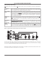
Typical auxiliary output wiring
Four auxiliary open collector outputs and one auxiliary output connections are available on the panel, as detailed below:
Reset Output
(RESET)
Turns on during the panel’s reset cycle. Can be used for resetting fire alarm system devices
such as roller-shutter doors or beam detectors. This output remains active for approximately
one second after all other outputs have returned to normal.
Remote Output
(REM)
Turns on during any new fire alarm condition or when the panel’s Silence/Resound Sounders
button is pressed to manually evacuate the building. The output turns off when the panel
is silenced. This output does not turn on when the Class Change or Alert inputs are asserted
(unless there are other fire alarm conditions present on the system). Note: If required, the
remote output can be disabled by the user. When the Remote Output is activated the
Remote Output light will be lit.
Auxiliary Fire
Output
(AUX)
Turns on during any fire alarm condition and off when the panel is reset. This output does
not turn on if the Class Change or Alert inputs are activated (unless there are other fire
alarm conditions present on the system). Note: If required, the Auxiliary Output can be
disabled by the user.
Fault Output
(FAULT)
This output is normally energised. When a fault occurs, the output turns off to ensure
failsafe operation even in the event of total power loss. If required, this output can be
disabled by the user.
Auxiliary 24V
Output
(AUX 24V)
This output provides a positive voltage supply for peripheral loads (such as relays) which are
controlled from the above outputs. The current consumed by this output must be considered
when calculating battery standby times. DO NOT CONNECT DOOR HOLDER CIRCUITS TO THIS
OUTPUT AS THEY WILL REDUCE BATTERY STANDBY TIME - USE A SEPARATE POWER SUPPLY.
Figure 7 : Typical auxiliary output wiring for open collector outputs
CONN8
RST
AUX
24V
OUTPUTS
REM
NO
AUX
NC
NO
C
NC
AUX
REM
RESET
FAULT
CONN10
C
FAULT
AUX 24V
–
–
–
–
+
+
+
+
FAULT
RELAY
RESET
RELAY
REMOTE
OUTPUT
RELAY
AUXILIARY
FIRE
RELAY
To protect the output stage, only 24V polarised relays with back EMF diodes should be used. If any of the relays
are to be used to switch Mains potentials, then suitable relays should be chosen, installed and wired accordingly,
so as not to compromise the electrical safety of the fire alarm system.
Connect each output to the relevant 5mm connector block on the Main Control PCB and terminate their screens
at the panel’s base earth post (see page 13 for more details).
CFP ECONOMY FIRE ALARM PANEL INSTALLATION & MAINTENANCE MANUAL • Approved Document No. DFU7002030 Rev 1 • Page 9 of 22
CFP 2/4/8 ZONE ECONOMY FIRE ALARM PANEL
SECOND FIX
Connecting the panel
Connecting the panel’s internal connections and PCBs should be undertaken immediately before commissioning.
Before you begin, we recommend you check all devices on the detector and sounder circuits are correctly connected
(see pages 7 and 8) and that cable integrity is verified throughout the installation.
Important: DO NOT use a high voltage insulation tester with any electronic devices connected.
Faults occurring in the wiring which are not picked up at this stage will almost certainly result in spurious and
intermittent faults when the equipment is energised.
Installing the Power Supply PCB
The panel’s Power Supply PCB combines the functions of a Mains to dc switched mode power supply unit, battery
charging unit and battery monitoring unit.
WHEN CONNECTED, THE POWER SUPPLY PCB STORES VOLTAGES AT UP TO 400Vdc AND MAY BE
LETHAL IF TOUCHED. DO NOT TOUCH THE PCB WHILST THE RED ‘HAZARDOUS VOLTAGES PRESENT’
INDICATOR IS LIT.
Under no circumstances should the fire alarm panel be operated without the Power Supply PCB correctly mounted
in the panel’s enclosure and the three retaining screws securely tightened.
The PCB should be positioned in the panel as shown in figure 8 on page 11.
Connecting the Mains
The general requirement for the Mains supply to this equipment is described on page 6.
DO NOT attempt to connect Mains to the panel until you are fully conversant with the layout and features of the
Power Supply PCB, as described above and in figure 8 on page 11.
The incoming Mains cable should be brought into the panel at the top right hand side of the enclosure and
terminated at the connector block (CONN1) on the Power Supply PCB.
Make sure the Mains earth wire is connected directly to this connector block and NOT to the secondary base earth
post which is provided for making off detector and sounder circuit screens.
The Power Supply PCB’s earth strap MUST be connected to the spade on the chassis earth post
before operation. The spade is compressed against a shoulder on the post via the lowest nut.
The earth post may appear loose, this is intended by design.
Connecting the standby batteries
Two new, good quality and fully charged 12V valve regulated lead acid (VRLA) batteries are required as the
emergency standby power supply for the panel. Caution: DO NOT use any other type of batteries due to the risk
of explosion.
The batteries should be connected in series and located in the panel’s enclosure as shown in figure 9 on page 11.
The battery leads, link wire and nylon cable ties are provided in the panel’s accessory pack. Run the battery leads
through the slits in the panel’s lower plastic ribs and secure the batteries into position using the nylon cable ties as
shown.
The panel’s sophisticated battery monitoring unit protects the batteries against deep discharge by activating a cut
off circuit when the standby supply voltage reaches 21V approx. If batteries are not fitted, are discharged or in poor
condition, a PSU fault will show at the fire alarm panel.
The capacity of the batteries used will depend upon the required standby time. To calculate the batteries required
for any given standby period, please refer to the calculation guide on page 21.
Always dispose of used batteries according to the battery manufacturer’s instructions.
CFP ECONOMY FIRE ALARM PANEL INSTALLATION & MAINTENANCE MANUAL • Approved Document No. DFU7002030 Rev 1 • Page 10 of 22
CFP 2/4/8 ZONE ECONOMY FIRE ALARM PANEL
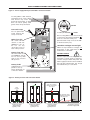
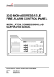
Figure 8 : Power Supply PCB layout and Mains connection details
Incoming Mains cable must be
segregated from other cables
and should only enter the
panel through either of these
drill outs. Good quality cable
glands must always be fitted.
CONN1
L N
L N
PSU earth strap
Do not operate the
panel without this
strap connected.
CONN1
PRIMARY
FUSE F1
L = Live; N = Neutral;
FUSE
1ATH 250V HRC
= Earth.
The incoming Mains earth wire must be
connected to the terminal marked
and not to the base earth post.
(The PSU earth strap connects the PCB
to the base earth post.)
Mains fuse (F1)
20 x 5mm 1A HRC
ceramic to IEC 127
(EN60127 Part 2).
Do not use any
other type or size of
fuse in this position.
Hazardous Voltages Present light
When lit red, hazardous voltages will
be present on the components in the
shaded area of the PCB.
Battery fuse (F2)
DO NOT TOUCH!
20 x 5mm 1A6 F to IEC
127 (EN60127 Part 2).
Do not use any other
type or size of fuse in
this position.
Certain components are charged to this
hazardous voltage during operation,
and this charge is bled away after the
Mains supply has been removed. When
the red light extinguishes, the charge
has leaked away to a safe level.
DO NOT
ADJUST
BATTERY FUSE
1.6AF
+ Red
Battery leads
PL2
AUX 24V
To
Battery
I Black
(supplied in the
panel’s accessory
pack). See below for
connection details.
PL1
To Main
Control
PCB
BAT1
Figure 9 : Battery location and connection details
Link wire
Take care to arrange
batteries so terminals
do not touch
Nylon
tie wraps
+
–
+
–
Run the battery leads
(supplied) through slits
in the plastic ribs
–
+
–
+
–
+
+
I
Location of small
sized batteries
typically 1.2 Ah
Location of medium
sized batteries
typically 2.1 Ah
–
+
+
I
Location of large
sized batteries
typically 3.0 Ah
+ RED
BLACK
Connection of leads
to Power Supply PCB
CFP ECONOMY FIRE ALARM PANEL INSTALLATION & MAINTENANCE MANUAL • Approved Document No. DFU7002030 Rev 1 • Page 11 of 22
CFP 2/4/8 ZONE ECONOMY FIRE ALARM PANEL
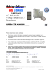
Installing the Main Control PCB
The panel’s Main Control PCB provides all the connections for the system’s detector circuits, sounder circuits,
auxiliary inputs and auxiliary outputs. It also provides the engineer with access to a wide range of engineering
functions, details of which appear later in this manual.
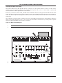
Before any connections can be made, the Main Control PCB must first be securely positioned inside the fire alarm
panel (see figure 10 below) using the five retaining screws. As the PCB is presented to the panel, remember to
attach the telecoms-style connecting cable to SKT2 on the reverse of the Main Control PCB and to PL1 on the Power
Supply PCB.
All of the 5mm connector blocks located across the top of the PCB can be removed to aid installation. Take care
when reconnecting them that you do so the correct way round. We recommend that you clearly label all system
wiring to reduce the likelihood of incorrect connection.
Figure 10 : Main Control PCB layout
Z5
+
–
Z6
Z7
+
–
–
+
Z8
SOUNDER
SC1
–
+
–
CIRCUITS
SC2
+
–
+
SC3
–
OUTPUTS
SC4
+
–
REM
AUX
24V
RST
AUX
FAULT
INPUTS
ALT CC 0V
CONN9
+
NC
CIRCUITS
–
NO
Z4
C
+
C
–
NC
Z3
NO
+
CONN8
DETECTOR
–
CONN7
Z2
CONN6
+
–
CONN5
Z1
CONN2
+
CONN10
SW1
SW5
CODE ENTRY(2)
ESCAPE ACCESS
SW2
FIRE
GENERAL
FIRE
SILENCE
INTERNAL
SOUNDER
CODE ENTRY(1)
ZONE1
ZONE2
ZONE3
SW6
ZONE4
ZONE5
ZONE6
ZONE7
ZONE8
FAULT
SILENCE/
RESOUND
SOUNDERS
WARNING
SW7
SW3
NEXT OPTION
CODE ENTRY(3)
RESET
REMOTE
OUTPUT
SUPPLY
I
SW4
ENABLE/DISABLE
LAMP TEST
CODE ENTRY(4)
SENSITIVE TO STATIC
ELECTRICITY - OBSERVE
PRECAUTIONS BEFORE
HANDLING
O
ACCESS LEVEL 2
ACCESSED
SYSTEM
FAULT
REPEATER
FAULT
GENERAL
DISABLEMENT
FAULT
OUTPUT
STATUS
AUX
OUTPUT
STATUS
OUTPUTS
DELAYED
REMOVING THIS CIRCUIT
BOARD EXPOSES HAZARDOUS
VOLTAGES - PLEASE REFER TO
INSTALLATION INSTRUCTIONS
OK
GENERAL
FAULT
4
3
5
2
6
PSU
FAULT
7
8
1
CAUTION - RISK OF EXPLOSION IF
INCORRECT TYPE OF BATTERIES FITTED.
DISPOSE OF USED BATTERIES ACCORDING
TO THE MANUFACTURERS INSTRUCTIONS.
TEST
REMOTE
OUTPUT
STATUS
9
0
10
DELAY MINUTES
VR1
SW8
ACCESS
LEVEL THREE
FUNCTIONS
SHORT
OPEN
CIRCUIT CIRCUIT
SOUNDER
STATUS
COINCIDENCE
DELAYS TEST
NONLATCHING
FOR OPERATIONAL DETAILS PLEASE
CONSULT THE MAINTENANCE MANUAL
CFP ECONOMY FIRE ALARM PANEL INSTALLATION & MAINTENANCE MANUAL • Approved Document No. DFU7002030 Rev 1 • Page 12 of 22
CFP 2/4/8 ZONE ECONOMY FIRE ALARM PANEL
Connecting the detector and sounder circuits
Incoming detector and sounder circuits should be connected to the relevant connector block on the Main Control
PCB as shown in figure 11 below.
For typical detector and sounder circuit wiring diagrams, please refer to pages 7 and 8.
Figure 11 : Detector and sounder circuit connection
See ‘Important notes
regarding the earthing
of screens’ section below
Z4
CIRCUITS
–
+
Z5
–
+
Z6
–
Z7
+
–
SOUNDER
Z8
+
–
SC1
+
–
SC2
+
–
CIRCUITS
+
SC3
–
OUTPUTS
AUX
REM
24V
RST
SC4
+
–
FAULT
AUX
INPUTS
ALT CC 0V
CONN9
+
NC
–
NO
Z3
C
+
C
DETECTOR
–
NC
Z2
CONN8
+
CONN7
–
CONN6
Z1
CONN2
+
CONN5
insulated
conductors
NO
insulated
screens
CONN10
Connecting the auxiliary inputs and outputs
Incoming auxiliary input and output cables should be connected to the relevant connector block terminals on the
Main Control PCB. If screened cables have been used, all screens should be adequately insulated and connected
between the nut and washers on the base earth post (see below) using eyed crimp connectors (as per the detector
and sounder circuit examples shown in figure 11 above).
For a full description of the inputs and outputs available on the panel, including typical wiring diagrams, please
refer to pages 8 and 9.
Important notes regarding the earthing of screens
All screens should be adequately insulated and
connected between the nut and washers on the base
earth post (see right) using suitable eyed crimp
connectors. Do not disturb the lower nut, this must be
secure to ensure earth continuity. The base earth post is provided
for terminating earth screens or drains and not as the main
earthing point. The system designer or installer must review the
external earth bonding (if required) with respect to the national
wiring rules. That is, if the type of installation requires protective
earth bonding, then this must be applied externally and in
conjunction with the type of earthing system employed on that
particular site. This must always be done with regard to the
appropriate national wiring rules.
crimped
connections
nut
spring
washer
plain
washers
screens
Do not untighten lower nut
CFP ECONOMY FIRE ALARM PANEL INSTALLATION & MAINTENANCE MANUAL • Approved Document No. DFU7002030 Rev 1 • Page 13 of 22
CFP 2/4/8 ZONE ECONOMY FIRE ALARM PANEL
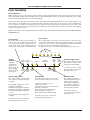
PROGRAMMING THE PANEL
An overview of the panel’s controls
Three control levels are available on the panel - general user (access level one), authorised user (access level two)
and engineer (access level three), as detailed below:
General user controls (access level one)
When the panel is in its normal state, the indicator lights on the panel front give a comprehensive overview of the
system’s current status. Any fire and fault conditions are clearly displayed, disablements highlighted and the status
of all outputs reported. The only functions that can be performed when the panel is in this state are:
• Muting the panel’s internal sounder.
• Putting the panel into access level two to make active the authorised user controls (see below).
Authorised user controls (access level two)
To avoid unauthorised changes to critical parts of the fire alarm system, certain fire alarm panel controls are only
available to authorised users. These include:
• Silencing the sounders.
• Resetting an alarm condition.
• Manually activating the alarm sounders (to evacuate a building)
• Testing the indicator lights.
• Disabling or enabling any (or all) of the following: zones, sounders, the fault output, the remote output, the
auxiliary fire output.
The authorised user controls can be accessed by entering the code 2 1 4 3 using the keypad or, by turning the
keyswitch to the ‘I’ position. For detailed information on how to use the general and authorised user controls,
please refer to the User Manual / Log Book.
Engineer controls (access level three)
It is possible to read or interrogate the site specific data at this level. The following controls are available to
competent service personnel only:
•
The invoking of test procedures.
To aid commissioning and routine maintenance checks, a non-latching ‘one man walk test’ facility is available.
When a detector or manual call point is triggered on any zone(s) in test, the alarm sounders operate for
approximately one second on and eight seconds off. This cycle continues until the cause of the alarm is removed
(either by the test smoke clearing from the detector or the manual call point being reset), at which point the
detector circuit also automatically resets. As the engineer walks around the site, additional devices on the zone(s)
in test can be checked with the momentary activation of the alarm sounders confirming correct operation.
Zones programmed for test, will be indicated at the panel by their Fault lights pulsing quickly in synchronisation
with the general Test light.
Should an alarm occur on a zone that is not programmed for test, the alarm will be processed in the normal way.
All zones that are in test will have their tests temporarily suspended until the alarm(s) from the other zones are reset.
At this point zone testing may resume. In other words, the alarm will operate correctly despite being in test mode.
•
Programming silenced sounders to resound, or not resound, when new zone in alarm.
Once the sounders have been activated after an alarm, then silenced, it is possible to set up the panel so that a
new alarm raised from another zone resounds, or does NOT resound, the sounders in accordance with EN54-2
{Clause 7.8d}.
•
Fault diagnosis.
A wide range of fault diagnosis features are available at access level three. These are described in detail on pages
17 to 20 of this manual.
Refer to pages 15 and 16 for details of how to gain access to the engineer controls and how to use them.
CFP ECONOMY FIRE ALARM PANEL INSTALLATION & MAINTENANCE MANUAL • Approved Document No. DFU7002030 Rev 1 • Page 14 of 22
CFP 2/4/8 ZONE ECONOMY FIRE ALARM PANEL
Accessing the engineer controls
Before programming the panel, please refer to page 14 for an overview of the various engineering functions
available and the effect their implementation will have on the way the system operates.
To gain access to the panel’s engineer functions, remove the panel lid using the Torx key provided and press the
ACCESS LEVEL THREE FUNCTIONS button on the Main Control PCB (see figure 12 below).
Figure 12 : Location of the panel’s programming tools on the Main Control PCB
SW1
SW5
CODE ENTRY(2)
ESCAPE ACCESS
SW2
FIRE
GENERAL
FIRE
SILENCE
INTERNAL
SOUNDER
CODE ENTRY(1)
ZONE1
ZONE2
ZONE3
SW6
ZONE4
ZONE5
ZONE6
ZONE7
ZONE8
FAULT
SILENCE/
RESOUND
SOUNDERS
WARNING
SW7
SW3
NEXT OPTION
CODE ENTRY(3)
RESET
REMOTE
OUTPUT
SUPPLY
I
SW4
ENABLE/DISABLE
LAMP TEST
CODE ENTRY(4)
SENSITIVE TO STATIC
ELECTRICITY - OBSERVE
PRECAUTIONS BEFORE
HANDLING
O
ACCESS LEVEL 2
GENERAL
DISABLEMENT
FAULT
OUTPUT
STATUS
REMOTE
OUTPUT
STATUS
AUX
OUTPUT
STATUS
OUTPUTS
DELAYED
OK
GENERAL
FAULT
4
3
5
2
6
PSU
FAULT
7
8
1
CAUTION - RISK OF EXPLOSION IF
INCORRECT TYPE OF BATTERIES FITTED.
DISPOSE OF USED BATTERIES ACCORDING
TO THE MANUFACTURERS INSTRUCTIONS.
ACCESSED
TEST
REMOVING THIS CIRCUIT
BOARD EXPOSES HAZARDOUS
VOLTAGES - PLEASE REFER TO
INSTALLATION INSTRUCTIONS
9
0
10
DELAY MINUTES
SYSTEM
FAULT
REPEATER
FAULT
SW8
ACCESS
LEVEL THREE
FUNCTIONS
OPEN
SHORT
CIRCUIT CIRCUIT
SOUNDER
STATUS
COINCIDENCE
DELAYS TEST
NONLATCHING
VR1
ACCESS LEVEL THREE FUNCTIONS button
When the ACCESS LEVEL THREE FUNCTIONS button is pressed for the first time, the Accessed light will be lit steady
and the first engineer function (TEST) will be selected and indicated by its yellow light flashing (see below).
Every time the ACCESS LEVEL THREE FUNCTIONS button is pressed the next engineer function is selected.
CFP ECONOMY PANEL CONTROLS
SYSTEM
FAULT
REPEATER
FAULT
SOUNDER
STATUS
OPEN
SHORT
CIRCUIT CIRCUIT
SW8
DELAYS
COINCIDENCE
ACCESS
NON LATCHING
LEVEL THREE
FUNCTIONS
TEST
Note: The engineer functions are graphically linked on the Main Control PCB by an ‘S’ shaped line (see above).
Engineer functions that are not supported on CFP Economy panels, e.g. COINCIDENCE, NONLATCHING, etc., will not
light.
Pressing the ACCESS LEVEL THREE FUNCTIONS button after the last selection returns the user to the first function.
To exit access level three at any time, press the ESCAPE ACCESS button.
Notes:
1. Access level three functions that are relevant to zones temporarily use the Zone Fault lights to show which
zones have been programmed for that function. This means any fault or disablement indication is suppressed
until the programming of the relevant function is complete.
2. When the panel’s lid is removed, it is still possible to access the panel’s authorised user control, i.e. access
level 2. This is done by entering the 2 1 4 3 entry code or, by turning the keyswitch to the ‘I’ position).
For detailed information on the authorised user controls, please refer to the separate User Manual / Log Book.
CFP ECONOMY FIRE ALARM PANEL INSTALLATION & MAINTENANCE MANUAL • Approved Document No. DFU7002030 Rev 1 • Page 15 of 22
CFP 2/4/8 ZONE ECONOMY FIRE ALARM PANEL
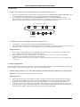
To program zones into test
1. Press the ACCESS LEVEL THREE FUNCTIONS button until the TEST light flashes (any zones that are already programmed for
test will now have their Zone Fault lights lit steady).
2. To change the test configuration press the NEXT OPTION button (zone 1’s Fault light will flash slower than the TEST light if
not programmed, or at the same rate if it is).
3. If required, toggle between the two states by pressing the ENABLE/DISABLE button.
4. To confirm your choice, press the NEXT OPTION button. This will move you to the next zone (if available).
5. Repeat steps 3 and 4 until the process is complete.
6. To finish the function, press the ESCAPE ACCESS button, or move onto the next programming function (SOUNDER STATUS) by
pressing the ACCESS LEVEL THREE FUNCTIONS button
Important: Before testing any of the zones you have programmed for test, you must first press the ESCAPE ACCESS button.
Any zone(s) in test will now be lit steady and the general Test light will also be lit. Testing can now commence. Remember to
take the relevant zones out of test when testing is complete.
To program the sounders function
1. Press the ACCESS LEVEL THREE FUNCTIONS button until the SOUNDER STATUS light flashes.
If the SOUNDER STATUS light flashes three times quickly with a longer off period, then an alarm in a new zone will resound
the sounders. If the SOUNDER STATUS light flashes with equal on-off periods, then an alarm in a new zone will NOT resound
the sounders.
2. If required, toggle between the two states by pressing the ENABLE/DISABLE button.
3. To finish the function, press the ESCAPE ACCESS button, or return to the first programming function (TEST) by pressing the
ACCESS LEVEL THREE FUNCTIONS button.
Note: ‘SYSTEM FAULT’, ‘OPEN CIRCUIT’ and ‘SHORT CIRCUIT’ options are for fault diagnosis purposes, as
detailed on pages 17 to 20.
The relevant part of the System Set-Up Data chart in the User Manual / Log Book must be updated if you
implement or make any changes to the program sounders functions.
CFP ECONOMY FIRE ALARM PANEL INSTALLATION & MAINTENANCE MANUAL • Approved Document No. DFU7002030 Rev 1 • Page 16 of 22
CFP 2/4/8 ZONE ECONOMY FIRE ALARM PANEL
FAULT DIAGNOSIS
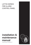
Fault indications
When a fault occurs on a critical part of the fire alarm system, the panel responds by activating its internal sounder
and illuminating the General Fault light and any other Fault light(s) relating to the fault. The panel’s fault output
will also activate (provided it has not been disabled).
The type of faults typically indicated at the fire alarm panel are highlighted below. A more precise diagnosis of
fault conditions is available at access level three (the summaries below refer to the sections you should read later
in this manual for further information). Unless otherwise stated, repairing any particular fault condition will
automatically clear the fault from the panel. If the panel is reset whilst faults still exist, the faults will reappear
after a short period of time.
Note: It is possible to mute the panel’s internal sounder at any time by momentarily pressing the SILENCE INTERNAL
SOUNDER button.
General Fault
Zone Faults
This light flashes yellow when there is a
fault on any part of the fire alarm system.
It is always lit in tandem with at least one
other Fault light which displays precise
information on the type of fault detected.
All of the panel’s zone circuits are monitored for open and short
circuit faults and detector head removal (unless there is an alarm
condition or the zone is in test or disabled). All faults are indicated
by the relevant Zone Fault light pulsing yellow.
For advice on how to correct this fault, see page 18, section 1.1.
1
2
3
4
5
6
8
7
Zone fault/disabled/test
Supply
Present
This light
should be lit
green at all
times. If off, see
power supply
faults, page 18,
section 1.2.
supply remote
present output
general
fault
power
supply
fault
test
accessed
general
disablement
fault
output
status
remote
output
status
sounder auxiliary
status output
status
system
fault
Remote Output Fault
This light flashes yellow
when there is a fault on the
output’s aux. 24V supply.
For advice on how to deal
with this type of fault see
page 20, section 1.5.
Power Supply Fault
System Fault
Sounder Fault
This light flashes yellow when
one or more of the following has
occurred:
This light flashes yellow when one or
more of the following has occurred:
All sounder circuits are
monitored periodically for
open and short circuit
faults (unless disabled or
in an alarm condition). If
any faults are detected,
this light pulses yellow.
1) The Mains supply is too low or
has failed completely.
2) Mains fuse (F1) has ruptured.
3) Battery fuse (F2) has ruptured.
4) The battery supply voltage is
too low.
5) The panel’s power supply unit
is faulty.
1) There is a microprocessor
“watchdog” fault.
2) The microprocessor’s site memory
has been corrupted.
3) The microprocessor’s program
menu has been corrupted.
4) The Main Control PCB is faulty.
For advice on how to
correct this fault see page
20, section 1.4.
For advice on how to correct this
fault see page 20, section 1.3.
For advice on how to correct this
fault see page 18, section 1.2.
CFP ECONOMY FIRE ALARM PANEL INSTALLATION & MAINTENANCE MANUAL • Approved Document No. DFU7002030 Rev 1 • Page 17 of 22
CFP 2/4/8 ZONE ECONOMY FIRE ALARM PANEL
1.1 Zone faults
•
To find out if an open circuit or head out fault has occurred on a detector zone:
1.
2.
Remove the panel’s lid using the Torx key provided and press the ACCESS LEVEL THREE FUNCTIONS button
on the Main Control PCB to gain access to the panel’s engineer functions (see below).
Continue pressing the ACCESS LEVEL THREE FUNCTIONS button until OPEN CIRCUIT light pulses.
Any existing Zone Fault lights are suppressed and the zone light(s) for any zone(s) with an open circuit
fault are lit, e.g. if the wiring on zone 6 is broken, zone 6’s Fault light will be lit.
CFP ECONOMY PANEL CONTROLS
SYSTEM
FAULT
REPEATER
FAULT
SOUNDER
STATUS
OPEN
SHORT
CIRCUIT CIRCUIT
SW8
DELAYS
COINCIDENCE
ACCESS
NON LATCHING
LEVEL THREE
FUNCTIONS
•
TEST
To find out if a short circuit fault has occurred on a detector zone:
1.
2.
Follow steps 1 and 2 detailed above until the SHORT CIRCUIT light pulses.
Any existing Zone Fault lights are suppressed and the zone light(s) for any zone (s) that have a short circuit
fault are lit, e.g. if the wiring on zone 4 has been shorted, zone 4’s Fault light will be lit.
Suggested actions:
1.
2.
Disconnect the faulty detector zone completely and refit the end-of-line capacitor at the panel. If the
fault condition clears this confirms there is a wiring fault.
Refit and double check the wiring and the end-of-line capacitor on the zone. Trace the fault with
consideration for the type of fault indicated (see above).
Note: A common short circuit fault is a detector head badly seated in a base which is not making a true
connection.
1.2 Power supply faults
A power supply fault indicates one, or more, of the following faults. Page 11 of this manual must be referenced
when carrying out any of the suggested action procedures described below.
•
The Mains supply voltage is too low or has failed completely, the Mains fuse (F1) has ruptured or the PSU has failed.
Symptoms: The panel runs on batteries, but not on Mains.
Suggested actions:
1.
2.
3.
Taking all due precautions, check Mains voltages are within range (see Technical Specifications, page 22)
by probing Live and Neutral connections at connector (CONN1). If not within range, repair Mains supply.
If within range and the red Hazardous Voltages Present light is not lit, check the Mains fuse (F1).
If the fuse is intact, the red Hazardous Voltages Present light on the Power Supply PCB may, or may not,
be lit. The PSU is faulty and should be replaced. Isolate the Mains supply and wait for the red Hazardous
Voltages Present light to extinguish before replacing the Power Supply PCB.
CFP ECONOMY FIRE ALARM PANEL INSTALLATION & MAINTENANCE MANUAL • Approved Document No. DFU7002030 Rev 1 • Page 18 of 22
CFP 2/4/8 ZONE ECONOMY FIRE ALARM PANEL
•
The battery fuse (F2) is ruptured.
Symptoms: The panel runs on Mains, but not on batteries.
Suggested actions:
1.
2.
3.
4.
5.
6.
•
Isolate the Mains supply and disconnect the batteries.
Remove the Main Control PCB and check the battery fuse (F2) on the Power Supply PCB for continuity.
If ruptured check the Power Supply and Main Control PCBs for signs of damage. If none found, replace
fuse with the correct type, ensuring the fuse clip is not damaged when re-inserting the fuse.
Refit the Main Control PCB and reconnect the batteries.
If the green Supply Present light is lit, reconnect the Mains supply and check that the power supply fault
has cleared. If the Supply Present light is not lit, either the Power Supply PCB or the Main Control PCB is
faulty and should be replaced.
If the battery fuse (F2) is intact, proceed to check the battery voltage / condition (see next section).
The battery voltage is too low, or in poor condition.
Symptoms: The panel runs on Mains, but may or may not run on batteries.
If the Mains supply has failed and the battery supply has been discharged to the point where the voltage is too
low (i.e less than 21V), the panel will automatically turn off to avoid damaging the batteries by allowing them
to deep discharge. The panel will not restart unless fresh, fully charged batteries are connected, or the Mains
supply is restored.
If the Mains supply has not failed, but the total battery voltage is less than 21V, the PSU may not charge the
batteries to avoid damage to the charging circuit. If the batteries can be charged, the panel will still show a
power supply fault until they have sufficient charge, at which point the power supply fault will automatically
be cleared. Depending on battery size and the depth of discharge, this may take several hours. If the batteries
are in poor condition they must be replaced.
If the batteries (or their leads) are high resistance, then this will also result in a PSU fault. This fault may be due to:
-
batteries that have been stored for many months
low quality batteries
old batteries
loose / poor connections to the batteries.
If the batteries are in good condition and all the other checks have been performed and no faults found, the
Power Supply PCB is faulty and should be replaced. Note: Batteries that are not connected, connected in
reverse, or with opposite polarities will also cause a power supply fault condition.
•
Supply Present light not lit.
If the Supply Present light is not lit one of the following faults has occurred:
1.
Both the Mains supply and the standby batteries have failed. This could be because the Mains supply has
failed and the batteries have been exhausted.
Suggested action: Restore the Mains supply and the Supply Present light should come back on.
However, if the batteries are discharged this will be recognised as a fault by the panel and indicated as
such. See ‘Battery voltage too low’ above.
2.
The Power Supply PCB, the Main Control PCB and/or the cable that connects them is faulty.
If the Mains supply is present (indicated by the red Hazardous Voltages Present light being lit on the
Power Supply PCB), check that the connector cable between the Power Supply PCB and the Main Control
PCB is fully inserted at both ends. If so, either the Power Supply PCB and/or the Main Control PCB and/or
the connector cable are faulty and should be replaced.
CFP ECONOMY FIRE ALARM PANEL INSTALLATION & MAINTENANCE MANUAL • Approved Document No. DFU7002030 Rev 1 • Page 19 of 22
CFP 2/4/8 ZONE ECONOMY FIRE ALARM PANEL
1.3 System faults
System faults are unique in that they do not automatically clear when rectified. Three different types of system
fault can occur; watchdog fault, site memory corruption fault or PLL (phase lock loop) fault.
•
System Fault light is lit.
Suggested action:
Press the panel’s RESET button and, if still in access level three, the ESCAPE ACCESS button. This should clear
the fault. If the fault persists, the Main Control PCB is faulty and must be replaced.
1.4 Sounder faults
•
To determine which of the panel’s four sounder circuits are faulty:
1.
Disconnect each sounder circuit from the Main Control PCB in turn and measure the resistance between
the two wires. A good circuit will present only the end-of-line resistor value. Any other resistance value
shows a fault.
2.
If the readings from all sounder circuits are correct, take their end-of-line resistors and connect them to
the sounder circuits at the panel without the sounder circuit wiring. If the fault still persists, the panel is
faulty and must be replaced.
3.
If a sounder circuit fault is detected, correct the fault and reconnect the sounder circuit. The sounder
fault will automatically clear within 60 seconds.
Note: If the sounder circuit is shorted and the alarm voltage applied, the relevant sounder fuse will trip. When
the fault is removed, the fuse will automatically reset.
1.5 Remote output faults
If the panel’s 24V auxiliary output (which is typically used to supply relays switched by the remote output) is
subject to current overload, its protection fuse will trip. This will result in the Remote Output Status light
illuminating.
Repairing the fault will reset the fuse and clear the associated Fault light.
MAINTENANCE
Periodic system maintenance should be carried out on the system as prescribed in the local design, maintenance
and installation regulations.
The Fire Alarm panel’s standby batteries should be checked for integrity of the connections, deposits indicating
venting, and a periodic load test with the Mains supply disabled to ensure adequate battery capacity. Both
batteries should be renewed if there is any doubt about their integrity.
CFP ECONOMY FIRE ALARM PANEL INSTALLATION & MAINTENANCE MANUAL • Approved Document No. DFU7002030 Rev 1 • Page 20 of 22
CFP 2/4/8 ZONE ECONOMY FIRE ALARM PANEL
STANDBY BATTERY CALCULATION GUIDE
The standby time of the fire alarm panel, after the Mains has failed, depends on the quiescent loading
of the panel, the alarm load of the panel and the capacity of the batteries.
To determine the capacity of batteries required for any given standby period, the following formula
should be used:
Standby Time in Ah = 1.25 x [(TxA) + H x (P+Z)]
The multiplier 1.25 is present to account for lost capacity over the life of the batteries.
H = Number of hours standby required
P = The quiescent current of the panel = 0.025A
This figure is with the Mains failed, internal sounder active and the Power Supply Fault and General Fault
lights lit. If there are other quiescent drains on the panel then these must be included.
Z = The total quiescent current of all zone devices
As a guideline, the quiescent current of most modern detectors is typically 0.00005A (50µA), and that of
manual call points is zero. To obtain accurate figures consult the device manufacturers’ own specifications.
A = The total alarm current of the sounders (plus any other devices connected to other alarm outputs).
T = The amount of time in hours required for the alarm (most commonly being half an hour).
Example 1:
The panel has 70 detectors each consuming 50µA each, 20 sounders at 20mA each, the required standby
time is 24 hours and the required alarm time is 0.5 hours.
Z = 70 x 0.00005 = 0.0035A
P = 0.025A
A = 20 x 0.02 = 0.4A
H = 24
T = 0.5
Standby Time in Ah = 1.25 x [(0.5 x 0.4) + 24 x (0.025 + 0.0035)] = 1.1Ah.
Therefore, batteries with at least 1.1Ah capacity are required.
Example 2:
The panel has 100 detectors each consuming 50µA each, 40 sounders at 20mA each, the required standby
time is 72 hours and the required alarm time is 0.5 hours.
Z = 100 x 0.00005 = 0.005A
P = 0.025A
A = 40 x 0.02 = 0.8A
H = 24
T = 0.5
Standby Time in Ah = 1.25 x [(0.5 x 0.8) + 72 x (0.025 + 0.005)] = 3.2Ah
Therefore, batteries with at least 3.2Ah capacity are required.
CFP ECONOMY FIRE ALARM PANEL INSTALLATION & MAINTENANCE MANUAL • Approved Document No. DFU7002030 Rev 1 • Page 21 of 22
CFP 2/4/8 ZONE ECONOMY FIRE ALARM PANEL
TECHNICAL SPECIFICATION
POWER SUPPLY SPECIFICATION
Mains supply voltage
230V 50/60Hz
Mains rated current
350mA maximum
Internal power supply
Total output current limited to
19V - 28.5V (27V nominal). Ripple 7V maximum (battery fault)
1.5A @ 230Vac (ImaxA = 146mA)
Maximum internal battery resistance
Ri max = 1.5Ω
Supply and battery charger monitored for failure
YES (battery charger is also temperature compensated)
Batteries monitored for disconnection & failure
YES
Batteries protected against deep discharge
YES (Deep discharge cut off approx. 21 volts)
Max. battery size and type
2 x 12V 3.2Ah VRLA (Valve Regulated Lead Acid) type, connected in series.
Minimum battery size 1.2Ah.
Mains fuse (F1)
Battery fuse (F2)
240V 1A HRC ceramic 20mm compliant with IEC (EN60127 PT2)
1.6A F 20mm compliant with IEC (EN60127 PT2)
Current draw from battery (Mains failed)
1.5A maximum
DETECTOR CIRCUIT SPECIFICATION
Number of circuits
2, 4 or 8 (1 zone per circuit) depending on model purchased
Max. cable length per circuit
500 metres
Line monitored for open circuit and short circuit
YES - DC monitoring
Line monitored for detector removal
YES. End-of-line monitoring device modules provided.
Maximum allowable impedance (each conductor)
20Ω
Maximum cable capacitance (per circuit)
0.27µF
Call point resistor value
Max. number of smoke / heat detectors
470 to 680Ω
25 per zone
Max. combined no. of detectors & manual call points
32 per zone
SOUNDER CIRCUIT SPECIFICATION
Number of circuits
4
End-of-line (EOL) resistor value
6800Ω 5% Tol. 0.25W (blue, grey, red, gold)
Each circuit monitored for open and short circuit
YES - Reverse voltage DC monitoring. Indicated by common fault.
Alarm voltage
27VDC maximum, 20VDC minimum (final battery voltage)
Sounder circuit fuses
Each circuit protected by fuses (200mA min. hold current; 400mA max. trip
current; approx. 50mA when tripped. Reset when faults removed).
Maximum total sounder output current to all outputs
4 x 200mA = 800mA
Maximum No. of bells @ 25mA
32
Maximum No. of electronic sounders @ 20mA
40 (sounders must be polarised)
AUXILIARY OUTPUTS
Type
Non monitored open collector transistor
Max. sink current
30mA each
Max open circuit voltage
27Vdc
Reset auxiliary output (RESET)
Active during reset cycle.
Remote auxiliary output (REM)
Active during any fire condition
Auxiliary fire output (AUX)
Active during any fire condition
Fault output (FAULT)
Active when no faults are present - failsafe to open circuit
24V aux. power output (for use with the above)
This output is protected by a resetable fuse (100mA min. hold current).
Fuse resets when fault removed.
AUXILIARY INPUTS
Class Change (makes sounders sound continuously)
Connect to 0V to trigger. Max input voltage 27V (non-latching).
Alert (makes sounders pulse intermittently)
Connect to 0V to trigger. Max input voltage 27V (non-latching).
DIMENSIONS
Physical size and weight
Size (OD) = 380 x 235 x 90mm approx. Weight = 1.75kg (without batteries)
OPERATING CONDITIONS
The components are selected to operate within their specification when the environmental conditions outside the enclosure
comply with class 3k5 of IEC 721-3-3 : 1978. Temperature range: -5 to +400C. Maximum relative humidity: 95%.
CFP ECONOMY FIRE ALARM PANEL INSTALLATION & MAINTENANCE MANUAL • Approved Document No. DFU7002030 Rev 1 • Page 22 of 22