1
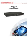
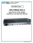
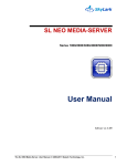
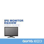
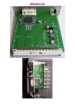
IFB-DVI-V2
IFB-DVI-V2
Installation and users Manual
DVI-D (HDCP) Interface board (IFB) for SONY Video Projectors
This Interface board will add a DVI-D (HDCP) input to any Sony CRT projectors including :
VPH-1251, VPH-1252, VPH-1270, VPH-1271, VPH-1272, VPH-1292, VPH-D50 (with IFB slot),
VPH-G70, VPH-G90.
1. Specifications :
DVI-D Input (100% digital). A HDMIDVI-D cable could be used to link to HDMI source
RGB 4:4:4 (8 bits) digital input (every HDMI source must be RGB 4:4:4 compatible)
Compatible with non-HDCP or HDCP sources
Directly compatible with any Sony IFB slot. Easy to install it within 5 min. (Plug&Play)
10 bits 175MHz triple video DAC - Inter-DAC : 2%
Output RGB-H/V video analog signals (0,7Vpp over 75 ohms impedance)
Shortest Analogue links (<8cm) on the IFB-DVI PCB for optimal picture quality
DVI video bandwidth in RGB outputs : 25-165MHz
Maximum resolutions : UWXGA (1920x1200) at 60Hz or SXGA (1280x1024) at 85Hz
computer compatible (PC, Mac)
HDTV ready (480p/576p/720p/1080i/1080p48/50/60 compatible)
HD-DVD and Blue Ray Disc players compatible
HDCP ready with embedded keys loaded
Energy management : DVI et VESA DPMS compatible
Ultra low power consumption in standby (3,5mA)
Maximum power : 0.4A under 5V (at 165MHz pixel clock)
On-board DC/DC converter (15V to 5V) with 90% efficiency (no-overheating) and extralow EMI signature
Four card power options (+5V from DVI/HDMI, +6V, SUB+5V or +15V from IFB bus)
Green LED to display active digital link
Red LED to display IFB-DVI selection
Low cost solution – Single IC solution
2. Installation :
• Completely shut down the projector Main (No standby please).
•
Unpack the IFB-DVI-V2 board from its antistatic bag. While unpacking this interface
board, please take good steps to avoid possible Electric Static Discharge. Before
touching the IFB-DVI-V2 card, please touch the chassis of the projector first (which is
grounded to earth).
IFB-DVI-V2
• Follow the steps in order (example using VPH-G70 projector) :
Tool required : Cross screwdriver / "Phillips" screwdriver
Locate the extension slot (B input) where IFB-40 stands– Using a cross screwdriver, unscrew its two thumb screws
Gently pull-out the old card by its handle – completely remove the IFB-40 from the B slot
Remove the two thumb screws from the IFB-40 back panel – Unscrew the two screws that secured the handle
IFB-DVI-V2
We’ve got now two thumb screws, one handle and its two screws – Locations of the parts on new IFB-DVI board
Screw-in the two thumb screws by hand. Attach the handle with its screws on the other side of the back panel
Secure the two handle’s screws with the cross screwdriver – The IFB-DVI board is now ready to be inserted
IFB-DVI-V2
In slot front view, locate the two plastic rail tracks – Insert the IFB-DVI-V2 within by following the two rail tracks !
Push the card as deeply as possible inside its slot and screw the lower part – Screw the upper one with the tool.
•
Connect the DVI-D cable to the IFB-DVI-V2 board and screw on its two locks
•
On the other end, connect the DVI-D cable to the DVD player or to the video processor with
a digital video output (DVI or HDMI).
•
First, power-up the DVD player or the video processor.
•
Then power-up the CRT projector and select the B slot video input. The Red LED of the
IFB-DVI interface (located close to the handle) must light itself to indicate that “B” input has
been selected.
•
Pop-up projector [Menu] and check that “B input” mode is set as “RGB”.
IFB-DVI-V2
•
Once the digital connection done, the Green led of the IFB-DVI interface (located right side
of DVI plug) must light itself to indicate that the digital communication protocol well
established with the interface.
•
The picture of the source must been displayed by the CRT projector.
•
The installation of the IFB-DVI-V2 interface board is now finished.
3. Notices :
By default, the IFB-DVI-V2 is powered by the projector itself using its +15V internal power
source (this PS is available in most of the Sony CRT projectors). This +15V power is
DC/DC converted to +5V by the hardware section located close to the 96 pins large
connector. In most cases, you should leave this mode of power as it is.
However, in case of +15V power missing, unmount the IFB-DVI board from the projector
IFB slot and choose one of the other mode of powering available :
Default power : Using 15V->5V DC/DC mode
Using DVI or HDMI source +5V powerI
Using +6V projector power mode
Using SUB+5V projector power mode
Beware: in this last power mode the IFB-DVI-V2 interface is still powered when the
projector is in its standby mode of operation. The Red LED may still be lit in this mode. The
benefit is that the source will still recognize the IFB-DVI card through its EDID memory
(powered) when the projector is in standby.
IFB-DVI-V2
When the IFB-DVI-V2 interface is unused and when its digital link is switched off, the
converter will switch off itself and enter in a standby mode (low power consumption).
This converter does not have any video adjustments (sharpness, gamma, colours, …). It
realizes a direct and pure digital to analog video conversion. To make these picture
adjustments, use the DVD player or video scaler parameter adjustments.
This converter does not modify the transmitted synchronization polarity. The analogue
synchronisation outputs signals (SYNC_H and SYNC_V) will have the same polarity as
these delivered by the digital source over the DVI or HDMI cable.
4. Recommandations :
Most video resolutions are programmed in the device (720P, 1080I HDTV, PC,...) but owing
to the limitation of the DDC memory size used by the card, some video configurations
(specific resolutions) are absent and it is necessary to have specific software to program
these special video resolutions (for example: 1080P48, 1080i72, … i.e. through
Powerstrip). Any resolution is programmable; the IFB-DVI-V2 remains synchronous.
In the case of the usage of a video utility (i.e. powerstrip) do not use a video resolution with
a pixelclock exceeding 165MHz.
In the case of a digital cable of more of 8M of length or of low quality, avoid using a video
mode possessing a pixelclock above 130MHz you might add artifacts to the picture
(unstable colour pixels - sparkling).
This converter does not contain any serviceable items but does have static electricity
sensitive circuits. Take the correct precautions to handle it (do not touch plugs pins).
Always use a competent service repair technician for repairs.
Never connect this interface to anything other than a Sony CRT projector.
IFB-DVI-V2
5. Troubleshooting
• Check that the Green LED of the IFB-DVI is lit. If this is not the case:
- Check that the DVI cable connection is working (well connected/secured with locks).
- Configure the DVD player or the video processor to output digital (DVI or HDMI) and
set it to the required resolution.
- If the power supply method of unit was updated to “+5V DVI-D” mode, check that the
digital source is able to deliver 400MA at 5V on its digital output (DVI or HDMI).
- If the digital cable is longer than 8M, it is preferable to use a cable of good quality and
use projector’s internal power mode (SUB+5V, +6V or +15V).
• If the projected picture presents pixels with random colours (sparkling noise) :
- The digital cable is too long or of poor quality, change with a shorter/better one.
- Reduce the working resolution (or reduce the pixelclock rate).
• If the picture of the projector does not post itself correctly (no sync) :
- Check that the projector is not configured for “Sync on the Green” or composite signal
modes (in this case change the video mode to RGB and sync mode to separated H/V)
- Check that the working resolution chosen on the DVD player or the video processor is
compatible with the projector video performances.
- Reduce the working resolution (or reduce the pixelclock rate).
• If the picture of the projector does not post itself correctly (poorly centered picture) :
- To correct the phase and/or the horizontal amplitude of the sweeping of the projector
to replace the picture in the screen (use [SIZE] and [SHIFT] keys on the remote).
- In the case of the using « Powerstrip », modify the parameters of front porch and back
porch to correct the position of the picture within the screen.
- If using 720p50 or 1080i50 European HDTV modes and active portion of the image
cannot full fit the complete width of the screen, try using 720p60/1080i60 US modes.
• If the picture of the projector is fuzzy:
- Reduce the working resolution (reduce the pixelclock rate).
• If the picture of the source does not appear on the projector:
- Check that the Red LED of the IFB-DVI is lit. This ensure that the correct input is
selected on the projector.
- Check that the Green LED of the IFB-DVI is lit. This confirms that the digital signal is
present and recognized by conversion unit.
• Using 1080P (50 or 60HZ) :
This video mode is close to the limit of the conversion circuit used. To be able to use it, it
maybe necessary to reduce the front porch and back porch parameters so that the
pixelclock rate delivered by the digital source does not exceed the 165MHZ bandwidth that
the IFB-DVI can accept.
Wish CRT projectors a longer life within digital video world !
♦
Thank to Andy (MadMrH) from UK and Clarence from USA for their help on translating this
document from French to English. Apologize for any remaining mistakes.