1
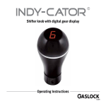
Digital Gear Display
Operating Instructions
Table of Contents
2
Page 3 ....................................................
About INDY-CATOR-DASH
Page 4 ....................................................
Package content
Page 5 ....................................................
Instrument installation
Page 7 ....................................................
Programming
Page 9 ....................................................
Troubleshooting
About INDY-CATOR-DASH
First, we would like to explain to you the function
of the digital gear display:
It works according to the principle of forming the
difference between two position sensors. As a
result, the selected transmission is displayed for
you. The electronic system recognises even the
smallest changes of positions of the gear lever
knob. It works completely independently of the
vehicle transmission. Only if a position change
is safely recognised as transmission change will
the display change.
This may take 1 - 1.5 s.
This transmission display is to serve as an aid.
We assume no warranty for correctness of the
display.
3
If the transmissions are not displayed correctly
for some reason, please repeat programming
with the motor/gear on operational temperature.
Depending on vehicle type and
gear position, extreme vehicle acceleration
may lead to short-term reading changes on the
display. This is based on the physical characteristics of the sensors and does not constitute any
malfunction.
Package content
1
2
3
4
5
6
7
8
4
2
Display instrument (1x)
Threaded ring (1x)
Reference box with power supply lines (1x)
Cable terminal clamp (2x )
Cable ties (3x)
Data cable 3 metres (1x)
Sensor box (1x)
Sensor cable / data cable short (1x)
5
8
7
1
6
3
Fig. 1
4
Instrument installation
1.1.1
The ignition should be switched off before installation. When installing in a universal instrument
carrier: Attach instrument with threaded ring in
the instrument carrier. Connect the 3 metres long
data cable (6) to one of the two rear sockets in
the instrument (fig. 2) and guide the data cable
carefully through the vehicle into the console
below the gear boot.
to ground) – you may use the included cable
clamps – find possible placement for reference
box but do not glue on yet!
The reference box may still need to be moved
when programming the gears.
Figure 2
Figure 3
1.1.2
Please read the respective assembly instructions
when using the Indy-Cator attachment set.
1.1.2
Connection to the board grid
Connect the plus line from the ignition and
ground line to the power supply lines of the reference box (3) (red to 12 Volt of the ignition, black
5
1.3.1
Sensor box assembly:
Connect the data cable (8) of the sensor box (7)
to the reference box and the display instrument
to the reference box (fig. 3)
(it is unimportant, which one of the two sockets
is used). Firmly attach sensor box to the switching rod in a twist-proof position using the
included cable ties.
1.3.2
Vehicles with reverse lock often have guide
parts that can be moved in longitudinal direction
around the actual gear lever. Please verify that
these guides have as little play as possible. A
moving sensor may lead to wrong gear recognition. Ideal attachment would be right at the gear
lever below the gear boot. (Fig. 4)
Figure 4
1.3.3
Switch on ignition briefly to check display or
connections. Reprogrammed display shows a
rotating or running bar.
Figure 5
6
Programming
2.1.1
The vehicle should be placed on a surface that
is as level as possible before programming.
Since the vehicle has to start in first gear after
programming (light acceleration), please ensure
now that there are no obstacles (20 metres
straight on are sufficient) and that traffic is not
impaired.
2.1.2
Start the engine – gear lever set to idle!
2.2.1
LCD Colour selection:
(Colour change by position change of the reference box). Keep the reference box button (3)
pressed for approx. 5 s until „C“ is displayed,
then let go of the button.
Tilt the reference box forwards and backwards
in your hand to start colour selection. The colour
changes in small nuances when the reference
box position is adjusted slightly. Briefly confirm
desired colour by pressing the push-button on
the reference box once. Display now indicates a
transverse bar:
7
2.3.1
Fastening the reference box:
The box should be placed as horizontally as possible in the area of the switching lever. Labelling
points up. (Fig. 5)
2.3.2
Remove protective foil from the adhesive strips,
position reference box and press on firmly.
Verify that the gear lever is still set to idle. Now
acknowledge the box position by briefly pressing
the push-button.
2.3.3
Gear programming now starts. Starting in first
gear, the display now shows all gears in sequence as flashing figures.
Once the display recognises acceleration, a running bar is displayed:
2.3.4
Display:
1 >
2 >
3 >
4 > 5 > 6 >
r >
please switch to first gear
please switch to second gear
please switch to third gear
please switch to fourth gear
please switch to fifth gear
(if the vehicle only has 4 gears – ignore display and leave it in 4th gear)
please switch to sixth gear (if the vehicle does not have any 6th gear – ignore display and leave it in 5th (or 4th) gear
please switch to reverse gear
(if there is no gear-change, the display change may take approx. 30 s).
1 > please switch back to first gear
A > Now accelerate the vehicle in first gear
(start driving as normal).
8

After a few seconds, the number of the active
gear is displayed – here it is the number 1.
Your Indy-Cator gear display is now programmed
and ready for operation. Please switch off the
motor. (Programming remains saved with the
display/ ignition switched off ). The gear boot
and any applicable covers in the car can now be
re-assembled.
Troubleshooting
If re-programming is required, press the button of the reference box until „C“ is displayed and start
again as described on page 6. If the previously selected colour is to be retained, please confirm it
with the button without moving the reference box again.
Display only shows running ring
Sensor box not connected?
Check cable connections
Gears not programmed
Programme gears
Gears are not recognised – displayed incorrectly
Sensor casing loose?
Reference casing loose?
Re-programme gears
Display goes out when the headlights are switched on
Ground cable (black) connected incorrectly
Ground cable (black) to chassis
9
Display remains black
Supply lines (red and black)must be checked. If the
supply lines are connected correctly (e.g. to DASH,
G, VOLT), the reference box status lamp is lit green.
(Fig. 6)
Figure 6
Check data line between reference box
and instrument
Changing LCD display brightness
Too many display instruments
connected to one reference box
Vehicle battery voltage too low
10