1
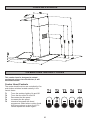
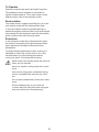
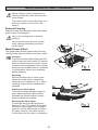
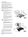
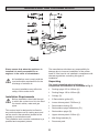
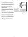
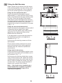
INSTRUCTION BOOKLET
COOKER HOOD
ZHC 925
Thank you for buying a Zanussi product.
To enable you to use your appliance effectively and safely, please read this instruction book carefully before using
the appliance and retain for future reference. If you require guidance in the use of the appliance or require further
information on Zanussi Products, please contact our Customer Care Department. For general enquiries concerning
your Zanussi appliance or for further information, visit our website at http:\\www.zanussi.co.uk
Customer Care Department
Zanussi
55-77 High Street
Slough
Berkshire
SL1 1DZ
Tel:
Fax:
08705 727727(*)
01753 538972
* Calls to this number may be recorded for training purposes.
To register ownership, please ensure you complete and return the guarantee card supplied with the appliance.
For the User
For the Installer
Important Safety Information
Technical Information
Electrical Connection
Your Appliance
Electrical Requirements
Electrical Connection
Operating Instructions
Cooker Hood Controls
To Operate
Recirculation
Extraction
Installing the Cooker Hood
Maintenance and Cleaning
External Cleaning
Metal Grease Filters
Charcoal Filters
To Remove/Replace the Charcoal
Filters
Changing the Light Bulb
Installation Requirements
Unpacking
Clearance Heights
Fitting the Wall Brackets
Fitting the Canopy Hood
Venting
Recirculation
Fitting the Chimney Stack
Service Force Centres
Something Not Working
Service and Spare Parts
Guarantee Conditions
Guide to use the instruction book
The following Symbols will be found in the text to guide you through the instruction book
Safety instructions
Step by step instructions
2
IMPORTANT SAFETY INFORMATION
These warnings are provided in the interests of your safety. Ensure that you understand them all before
installing or using this appliance. Your safety is of paramount importance. If you are unsure about any of
the meanings of these warnings contact the Customer Care Department.
Installation
•
Child Safety
Any installation work must be undertaken by a
qualified electrician or a competent person.
•
This hood must be installed in accordance with the
installation instructions and all measurements must
be adhered to.
•
If the cooker hood is installed for use above a gas
appliance then the provision for ventilation must be
in accordance with the Gas Safety Codes of Practice
BS.6172, BS.5440 and BS.6891 (Natural Gas) and
BS.5482 (LP Gas) 1994, the Gas Safety (Installation
& Use) Regulations, the Building Regulations issued
by the Department of the Environment, the Building
standards (Scotland) (Consolidated) Regulations
issued by the Scottish Development Department.
•
This appliance is designed to be operated by adults.
Children should not be allowed to tamper with the
controls or play with the appliance.
During Use
•
The fan motor of this cooker hood incorporates a cutout device which will operate if the cooker hood is
installed below the minimum height recommended
under section ‘Clearance Height’, or if the motor
becomes overheated. If the cut-out device is
activated, switch off the fan motor and allow the
cooker hood to cool. The cut-out device will reset
itself when the fan motor has cooled significantly.
•
It is dangerous to alter the specifications or modify
this product in any way.
•
When installed between adjoining wall cabinets the
wall cabinets must not overhang the hob.
•
If the room where the hood is to be used contains a
fuel burning appliance such as a central heating boiler
then its flue must be of the room sealed or balanced
flue type.
•
If other types of flue or appliances are fitted ensure
that there is an adequate supply of air to the room.
•
The ducting system for this appliance must not be
connected to any existing ventilation system which
is being used for any other purpose.
•
Do not install above a cooker with a high level grill.
•
This product is for domestic use only.
•
Never leave frying pans unattended during use as
over-heated fats and oils might catch fire.
•
Never do flambé cooking under this cooker hood.
•
Do not leave naked flames under the hood.
Maintenance and Service
3
•
This appliance can be a hazard if the synthetic paper
and charcoal filters are not replaced as
recommended.
•
Under no circumstances should you attempt to repair
the appliance yourself. Repairs carried out by
inexperienced persons may cause injury or more
serious malfunction. Refer to your local Zanussi
Service Force Centre. Always insist on genuine spare
parts.
YOUR APPLIANCE
OPERATING INSTRUCTIONS
This cooker hood is designed to extract
unpleasant odours from the kitchen, it will
not extract steam.
Cooker Hood Controls
The cooker hood functions are controlled by five
push button switches located centrally in the
control fascia.
T1
T2
T3
T4
T5
T1
Turns the worktop lighting On and Off
Turns the fan motor On and Off
Decreases the fan speed
Increases the fan speed
Intensive fan speed with timed
programme. Select when cooking foods
with strong odours or when frying. To
cancel depress the button again.
T2 T3 T4
F
4
T5
C
To Operate
Select the required fan speed and light if required.
The appliance can be installed to recirculate or
extract contaminated air. The cooker hood is more
effective when used in the extraction mode.
Recirculation
The cooker hood is supplied specified for use in the
recirculation mode with the charcoal filter fitted.
In the recirculation mode the contaminated air is
passed through the charcoal filters to be purified and
recirculated into the kitchen through the recirculation
grilles in either side of the chimney stack.
Extraction
In the extraction mode the contaminated air enters
the cooker hood passing through the grease filters
and is passed out through the ducting into the
atmosphere.
To obtain the best performance when cooking it is
advisable to switch the cooker hood on for a few
minutes before you start cooking and leave it
running for about 15 minutes after finishing.
When used in the ducting mode the charcoal
filters are not required.
Never do flambé cooking under this cooker
hood.
Never leave frying pans unattended during
use as overheated fats and oils can catch
fire.
Do not leave naked flames under the cooker
hood.
Ensure heating areas on your hob are
covered with pots and pans when using the
hob and cooker hood simultaneously.
5
MAINTENANCE AND CLEANING
Before carrying out any maintenance or
cleaning isolate the cooker hood from the
mains supply.
The cooker hood must be kept clean, as a
build up of grease or fat can be a fire
hazard.
External Cleaning
Wipe the cooker hood frequently with warm soapy
water using a mild detergent.
Never use scouring pads or abrasive
cleaners.
Never use excessive amounts of water
when cleaning particularly around the
control panel.
Metal Grease Filters
The grease filters absorb grease and dust during
cooking to help keep the cooker hood clean inside.
Cleaning
The filters must be washed when the LED
lamp on the push button switch T2 starts to
flash or at least once every month, using a
normal household detergent; their compact
dimension also enables them to be washed
in a dishwasher. Allow to dry completely
before replacing.
GF
Fig. 1
Replacing
Remove the filters one at a time, press
against the metal catch to release the
spring catch as illustrated in Fig. 1. When
replacing, ensure that the handles face
outwards.
F
FA
Enabling the alarm signal
The hood is already primed to trigger an
alarm when the grease filters become
saturated with grease and this function
does not need to be enabled.
GF
Resetting the alarm signal
To reset the alarm proceed as follows: Depress T1 and T2 to switch off the lights
and the fan motor; press T4 for at least 3
seconds, until the LED flashes to confirm
the alarm has reset. The alarm will only
function when the fan motor is switched on.
Fig. 2
6
Charcoal Filters
In the recirculation mode the charcoal filters
absorb smells and unwanted odours.
The charcoal filters cannot be cleaned or
regenerated, and must be replaced when the
Instensive speed LED T5 starts to flash, or at
least once every 3 months.
Attention: If, when used in the recirculation
mode both the T2 and T4 LED indicator lights
begin to flash simultaneously this indicates the
both the charcoal filter needs replacing and the
grease filters need cleaning.
Replacing the charcoal filter
First remove the metal grease filter GF
as illustrated in Fig. 1.
Carefully remove the screw from the
centre of the charcoal filter, while
holding the filter securely.
Clean the grille before replacing the
charcoal filter.
FA
To replace the charcoal filter, place the
filter over the inlet grille and while
holding the filter with one hand insert
the screw and tighten by hand as
illustrated in Fig. 3.
Fig. 3
This appliance can be a possible fire
hazard if the grease and charcoal filters
are not cleaned and replaced as
recommended.
Changing the Light Bulb
Unsrew the two screws from the frame
around the lamp lens as illustrated in
Fig. 4.
Remove the lamp by carefully pulling it
downwards until it clears the holder.
When replacing the lamp, ensure the
two pins are correctly positioned before
inserting the lamp into the holder by
applying carefull pressure to the lamp
lens.
If one of the halogen lamps has failed to
function check that the lamps is correctly
seated into the holder. If the lamp has failed
then it should be replaced with a 20W
spotlamp.
Fig. 4
Replacement filters and light bulbs can be
obtained from your local Service Force
Centre.
7
SOMETHING NOT WORKING
If, having followed these instructions carefully, your cooker hood fails to work properly please carry out
the following checks.
Solution
Symptom
The cooker hood will not start
• Check the hood is connected to the electricity supply.
• Check that the fan speed control is set to 1, 2 or 3.
The cooker hood is not working effectively
• The fan speed is set high enough for the task.
• The grease filter is clean.
• The kitchen is adequately vented to allow the entry
of fresh air.
• If set up for recirculation, check that the charcoal
filter is still effective.
• If set up for extraction, check that the ducting and
outlets are not blocked.
The cooker hood has switched off during
operation
• The safety cut-out device has been tripped.
• Turn off the hob and then wait for the device to reset.
In-guarantee customers should ensure
that the above checks have been made as
the engineer will make a charge if the fault
is not a mechanical or electrical
breakdown.
If after all these checks, the problem persists,
contact your local Service Force Centre,
quoting the model and serial number.
Please note that it will be necessary to
provide proof of purchase for any
in-guarantee service calls.
SERVICE AND SPARE PARTS
If you require an engineer or wish to purchase spare
parts contact your local Service Force Centre by
telephoning:
For general assistance with your appliance or for
information on Zanussi products please contact our
Customer Care Department.
Customer Care Department,
Zanussi
55-77 High Street
Slough
Berkshire
SL1 1DZ
08705 929929
Your telephone call will be routed to your local
Service Force Centre. The addresses are listed at the
back of the book.
Tel: 08705 727 727(*)
*calls to this number may be recorded for training
purposes.
8
GUARANTEE CONDITIONS
We, Zanussi, undertake that if within twenty four months of the date of the purchase this Zanussi built-in
product or any part thereof is proved to be defective by reason only of faulty workmanship or materials,
the company will, at our option repair or replace the same FREE OF ANY CHARGE for labour, materials
or carriage on condition that:
•
The appliance has been correctly installed and used only on the electrical supply stated on the rating
plate.
•
The appliance has been used for normal domestic purposes only, and in accordance with the
manufacturer’s operating and maintenance instructions.
•
The appliance has not been serviced, maintained, repaired, taken apart or tampered with by any
person not authorised by us.
•
•
All service work under this guarantee must be undertaken by a Zanussi Service Force Centre.
Any appliance or defective part replaced shall become the property of this company.
Home visits are made between 8.30am and 5.30pm Monday to Friday. Visits may be available outside
these hours in which case a premium will be charged.
EXCLUSIONS
This Guarantee does not cover:
•
Damage or calls resulting from transportation, improper use or neglect, the replacement of any
lamps or removable parts of glass or plastic.
•
Costs incurred for calls to put right appliances improperly installed or calls to appliances outside the
United Kingdom.
•
Appliances found to be in use within a commercial environment, plus those which are the subject of
rental agreements.
•
Products of Zanussi manufacture which are not marked by Zanussi.
This guarantee is in addition to your statutory and legal rights.
ZANUSSI EUROPEAN GUARANTEE
If you should move to another country within Europe then your guarantee moves with you to your new
home subject to the following qualifications:
•
•
The guarantee starts from the date you first purchased the product.
•
•
•
This guarantee relates to you and cannot be transferred to another user.
The guarantee is for the same period and to the same extent for labour and parts as exists in the
new country of use for this brand or range of products.
Your new home is within the European Community (EC) or European Free Trade Area.
The product is installed and used in accordance with our instructions and is only used domestically,
i.e. a normal household.
Before you move please contact your nearest Customer Care Centre, listed below, to give them
detailsof your new home. They will then ensure that the local Service Organisation is aware of
your move and able to look after you and your appliances.
France
Germany
Italy
Sweden
United Kingdom
Senlis
Nurnberg
Pordenone
Stockholm
Slough
+33 (0)3 44 62 22 22
+49 (0)911 323 2600
+39 (0)1678 47053
+46 (0)20 78 77 50
+44 (0)1753 219 897
9
INSTALLATION INSTRUCTIONS
It is dangerous to alter the specifications or attempt to modify this product in any way.
Technical information
DIMENSIONS
HEIGHT OF CANOPY:
HEIGHT OF CHIMNEY:(UPPER SECTION)
(LOWER SECTION)
WIDTH OF CANOPY:
DEPTH OF CANOPY:
71.5mm
215mm
728.5mm
898mm
485mm
ELECTRICAL SUPPLY
VOLTAGE:
(~50Hz)
POWER CONSUMPTION:
FAN MOTOR:
LAMPS:
(2 x20W Halogen)
220-240V
240W
200W
40W
SUITABLE FOR INSTALLATION ABOVE:
ELECTRIC HOB:
GAS HOB:
SLOT-IN ELECTRIC COOKER:
SLOT-IN GAS COOKER:
7KW (MAX)
10KW (MAX)
12.4KW (MAX)
13.5KW (MAX)
Note: CE Marking certifies that this appliance complies with the requirements
laid down in EEC directive 89:336. (Electromagnetic compatibility) and
subsequent modifications and Low Voltage directive 72/23/E.
ELECTRICAL CONNECTIONS
THIS APPLIANCE MUST BE EARTHED
Electrical Requirements
This appliance is fitted with a 3 core mains cable
and must be permanently connected to the
electricity supply via a double-pole switch having
3mm minimum contact gap on each pole. A
Switched Fuse Connection Unit to BS.1363 Part
4, fitted with a 3 Amp fuse, is a recommended
mains supply connection accessory to ensure
compliance with the Safety Requirements
applicable to fixed wiring instructions.
Any permanent electrical installation must
comply with the latest I.E.E. Regulations and
local Electricity Board regulations. For your own
safety this should be undertaken by a qualified
electrician e.g. your local Electricity Board, or a
contractor who is on the roll of the National
Inspection Council for Electrical Installation
Contracting (NICEIC).
Electrical Connection
This appliance conforms to BS.800:1988 and
EEC Directive No. 78 308 regarding suppression
of radio and television interference.
Before connecting to the mains supply ensure
that the mains voltage corresponds to the
voltage on the rating plate inside the cooker
hood.
10
INSTALLING THE COOKER HOOD
2
S
G
A
G
B
I
C
P
P1
R
Fig. 5
Please ensure that when the appliance is
installed it is easily accessible to an
engineer in the event of a breakdown.
All installations must comply with the
local authorities requirements for the
discharge of exhaust air.
Incorrect installation may affect the
safety of this cooker hood.
Installation Requirements
Before installation check that the wall
to which the cooker hood is to be fitted
for electric cables, water and gas
pipes.
This cooker hood is designed to be fixed to
any vertical surface over a cooking area, and
can be used in the extraction (ducted to the
outside) or recirculation mode.
The installation work must be undertaken by a
qualified and competent person.
The manufacturer disclaims any responsibility for
damage due to incorrect installation of the cooker
hood or if the hood is not installed in compliance with
relevant regulations controlling this type of
installation.
Unpacking
The hood is supplied with the following
components for installation as illustrated in Fig. 5:
•
•
•
•
•
•
•
•
•
•
•
11
Ducting spigot 150 to 120mm (A)
Ducting flange 120 to 125mm (B)
Canopy (C)
2 Recirculation grilles (G)
Lower chimney stack 728.5mm (I)
Recirculation ducting (P)
Recirculation spigot extensions (P1)
Recirculation spigot (R)
Upper chimney stack 215mm (S)
Wall fixing brackets (2)
Document pack.
Clearance Heights
The cooker hood is designed to be fitted over a
cooking appliance at the clearance heights stated,
providing the maximum output of the appliance
beneath does not exceed the maximums quoted in
the Technical Specifications.
If the output of the appliance below the cooker
hood exceeds the maximum outputs quoted,
please refer to the cooker manufacturer’s
installation instructions.
Hob
A minimum clearance height of 650 mm (251/2 ins)
is required when installed above a built-in electric
hob, or 700 mm (271/2 ins) when installed above a
built-in gas hob.
A: Built-in Electric Hob:
B: Built-in Gas hob:
C: Slot-in Electric Cooker:
D: Slot-in Gas Cooker:
A minimum clearance height of 685 mm (27 ins) is
required when installing above a slot-in electric
cooker, or 787 mm (301/2 ins) when installed above
a slot-in cooker.
When installed between adjoining wall cabinets,
the wall cabinets must not overhang the hob and
the distance between the underside of the cabinet
and the worktop must be 450 mm (171/2 ins), a gap
of 50 mm (2 ins) must be maintained either side of
the hob.
This cooker hood must not be installed
above a cooking appliance with a high
level grill.
12
650mm minimum clearance
700mm minimum clearance
685mm minimum clearance
787mm minimum clearance
Fig. 6
Fitting the Wall Brackets
1
210
260
20
d = 948 min
Fixing the first wall brackets No 2
Draw a horizontal line through the vertical
approximately 1 or 2mm from the ceiling or from
a line on the wall where the upper chimney stack
will finish. Place the top edge of the bracket
under the line on the wall aligning the centre of
the bracket with the vertical line. If, the alignment
is correct mark the centres for the key hole
bracket fixing screws (not supplied) as illustrated
in Fig. 7 - a.
X
2
1
Draw a vertical line on the wall, from the centre
of the cooking appliance up to the ceiling, using
a spirit level and marker pen. This is to ensure
the correct vertical alignment of the appliance.
Fixing the second wall bracket No 2
Draw a horizontal line through the vertical at X. X
is determined by the height of the upper
chimney. Place the bottom edge of the bracket
against the line, aligning the centre of the
bracket with the vertical line.
If, the alignment is correct mark the centres for
the keyhole fixing screws (not supplied) as
illustrated in Fig. 7 - a.
Fig. 7 - a
Drill the holes for the fixing screws and fix the
wall brackets.
Ensure that the distance between the lowest
point of the hood and the cooking appliance
beneath meets the clearance requirements
quoted above.
Fixing holes for the canopy
Draw a horizontal line through the vertical, using
a spirit level and marker pen at d=948mm (min.)
as illustrated in Fig. 7 - a.
H min 650
Drill the holes for the fixing 4.2x44.4mm screws
using an 8mm masonry drill. Tighten the screws,
leaving a gap between the screw heads and the
wall of 5-6mm to enable the canopy to be hung
on the screws. The canopy can be adjusted in
height once in position from 0-20mm.
Note: If the hood is to be installed onto a
hollow construction or plaster or partition
board wall then special fixings will be
required (not supplied).
Fig. 7 - b
13
Fitting the Canopy Hood
Before starting to fix the canopy it will be
necessary to adjust the support brackets
S1 by turning the screws clockwise until
the limit of the thread is reached as
illustrated in Fig. 8.
a-
Hook the canopy onto the two
4.2x44.4mm screws1 fitted as described
above and illustraed in Fig. 9.
b-
Using a screw driver and spirit level,
adjust the screws S1 until the canopy is
level. Once the canopy is level, tighten
up the wall fixing screws to secure the
canopy.
S1
Electrical connection and working
test
Before fitting the chimney to the canopy make
the electrical connection as described in the
section titled “ELECTRICAL CONNECTION”.
When the electrical connection has been made,
test the three speed fan and worktop
illumination.
S1
Fig. 8
1
1
Venting
1
The hood is more effective when used in the
extraction mode (ducted to the outside).
Venting kits may be purchased through your
retailer or DIY store, and must be ducted to
an outside vent of 125mm (5”).
The ducting used must be manufactured
from fire retardent material conforming
to the relevant British Standard or DIN
4102-B1.
Fig. 9
When the cooker hood is ducted to the
outside the charcoal filter must be removed.
P1
P1
Recirculation
The cooker hood is supplied specified for use
in the recirculation mode, with the charcoal
filters fitted.
R
P
In the recirculation mode contaminated air is
passed through the charcoal filters to be
purified and recirculated into the kitchen
through the grille outlets on either side of the
chimney (G).
To assemble the recirculation duct, place the
‘push-fit’recirculation extension pipe P over
the spigot on the top of the canopy; place the
‘push-fit’ spigot R on to the pipe P and insert
the extension pieces P1 into either side of the
spigot as illustrated in Fig. 10.
I
G
Fig. 10
14
Note: The two venting grilles must not be fitted
into the lower chimney (I) until the chimney has
been installed.
Extraction
The charcoal filter is not required in this mode
and should be removed.
Ducting
The ducting used must be 150mm (6ins), or
125mm (5ins) in diameter.
If possible duct through the wall immediately
above the canopy.
For the best performance use the shortest
possible duct run and the minimum number of
bends.
Where flexible ducting is fitted it should not be
turned through very tight bends as this may
impair the performance of the hood.
It is recommended a maximum length of 3
metres, to be installed, to be reduced 1 metre for
each 90o bend installed in the ducting run.
If the distance is greater than 3 metres the
efficency of the hood could be impaired.
B
A
The diameter of the spigot on top of the hood is
150mm (6ins). When 125mm ducting is to be
used it will be necessary to install the ducting
adapter (A) 150mm (6ins) to 120mm (5ins) and
the ducting collar (B) 120mm to 125mm as
illustrated in Fig. 11.
A
Fig. 11
If the room where the cooker hood is to
be used contains a fuel burning appliance
such as a central heating boiler, then its
flue must be of the room sealed or
balanced flue type.
If other types of flue or appliances are
fitted ensure that there is an adequate
supply of air to the room.
The cooker ducting (extraction mode)
must never be connected to central
heating flues, radiators or water heaters
etc.
15
Fitting the Chimney Stack
2
The chimney consists of two sections. The upper
chimney measures 215mm and the lower chimney
(with the holes for recirculation on either side)
measures 728.5mm.
S
To fit the upper section (S) first expand
the chimney slightly to allow it to be fitted
over the brackets 2, and then secure the
chimney stack to brackets using the four
self tapping screws provided as illustrated
in Fig. 12.
2
G
I
To fit the lower chimney section (I) expand
the chimney slightly to allow it to be fitted
over the upper chimney (S) and the
canopy (C) as illustrated in Fig. 8.
C
Secure the bottom of the chimney to the
canopy using the self tapping screws
provided as illustrated in Fig. 12.
Fig. 12
After the chimney has been secured into
position, insert the two plastic
recirculation grilles in to the apertures on
each side of the chimney. The grilles are
marked with two arrows and should be
fitted with one arrow pointing upwards and
the other toward the front.
Fig. 13
When the hood is used in the recirculation
mode ensure that the grilles are properly
secured to the recirculation spigot R as
illustrated in Fig. 13.
16
17
18
19
© Electrolux Household Appliances Limited 2001
4329620 03 - 010910