1
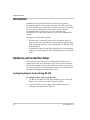
XTR 6-110
XTR 8-100
XTR 12-70
XTR 20-42
XTR 33-25
XTR 40-21
XTR 60-14
XTR 80-10.5
XTR 100-8.5
XTR 150-5.6
XTR 300-2.8
XTR 600-1.4
XTR 6-220
XTR 8-200
XTR 12-140
XTR 20-84
XTR 33-50
XTR 40-42
XTR 60-28
XTR 80-21
XTR 100-17
XTR 150-11.2
XTR 300- 5.6
XTR 600-2.8
Operating Manual
XTR 850 Watt and
1700 Watt Series
Programmable DC
Power Supply
XTR 850 Watt and 1700
Watt Series Programmable
DC Power Supply
Operating Manual
About Xantrex
Xantrex Technology Inc. is a world-leading supplier of advanced power electronics and controls with
products from 50 watt mobile units to 2.5 MW utility-scale systems for wind, solar, batteries, fuel cells,
microturbines, and backup power applications in both grid-connected and stand-alone systems. Xantrex
products include inverters, battery chargers, programmable power supplies, and variable speed drives
that convert, supply, control, clean, and distribute electrical power.
Trademarks
XTR 850 Watt and 1700 Watt Series Programmable DC Power Supply is a trademark of Xantrex
International. Xantrex is a registered trademark of Xantrex International.
Other trademarks, registered trademarks, and product names are the property of their respective owners
and are used herein for identification purposes only.
Notice of Copyright
XTR 850 Watt and 1700 Watt Series Programmable DC Power Supply Operating Manual© April 2006
Xantrex International. All rights reserved.
Exclusion for Documentation
UNLESS SPECIFICALLY AGREED TO IN WRITING, XANTREX TECHNOLOGY INC.
(“XANTREX”)
(A) MAKES NO WARRANTY AS TO THE ACCURACY, SUFFICIENCY OR SUITABILITY OF
ANY TECHNICAL OR OTHER INFORMATION PROVIDED IN ITS MANUALS OR OTHER
DOCUMENTATION.
(B) ASSUMES NO RESPONSIBILITY OR LIABILITY FOR LOSSES, DAMAGES, COSTS OR
EXPENSES, WHETHER SPECIAL, DIRECT, INDIRECT, CONSEQUENTIAL OR INCIDENTAL,
WHICH MIGHT ARISE OUT OF THE USE OF SUCH INFORMATION. THE USE OF ANY SUCH
INFORMATION WILL BE ENTIRELY AT THE USER’S RISK; AND
(C) REMINDS YOU THAT IF THIS MANUAL IS IN ANY LANGUAGE OTHER THAN
ENGLISH, ALTHOUGH STEPS HAVE BEEN TAKEN TO MAINTAIN THE ACCURACY OF THE
TRANSLATION, THE ACCURACY CANNOT BE GUARANTEED. APPROVED XANTREX
CONTENT IS CONTAINED WITH THE ENGLISH LANGUAGE VERSION WHICH IS POSTED
AT WWW.XANTREX.COM.
Date and Revision
April 2006 Revision A
Part Number
975-0200-01-01
975-0200-01-01
ii
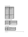
Product Numbers (FGAs)
850 Watt Models
1700 Watt Models
XTR_6-110
XTR_6-220
XTR_8-100
XTR_8-200
XTR_12-70
XTR_12-140
XTR_20-42
XTR_20-84
XTR_33-25
XTR_33-50
XTR_40-21
XTR_40-42
XTR_60-14
XTR_60-28
XTR_80-10.5
XTR_80-21
XTR_100-8.5
XTR_100-17
XTR_150-5.6
XTR_150-11
XTR_300-2.8
XTR_300-5.6
XTR_600-1.4
XTR_600-2.8
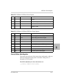
Part Numbers for Rack Mount Kits
Rack Mount Kit
Part Number
Dual XTR 850 Watt
RM-D-XTR1
Single XTR 850 Watt
RM-S-XTR1
Rack mount rails for
RM-XFR
XTR 1700 Watt Series
Contact Information
Telephone: 1 800 667 8422 (toll free North America)
1 360 925 5097 (direct)
Fax:
1 360 925 5143
Email:
customerservice@xantrex.com
Web:
www.xantrex.com
975-0200-01-01
iii
About This Manual
Purpose
The Operating Manual provides installation and operating information for
the XTR 850 Watt and 1700 Watt Series Programmable DC Power Supply.
Scope
The Manual provides safety information, features and specifications,
installation procedures, functional test procedures, and operating procedures
for both local (front panel) operation and remote operation.
The Manual does not provide information on the GPIB and Ethernet
(ENET) interface options. See the XTR 850W and 1700W GPIB and
Ethernet Interface Option Operating Manual.
Audience
The Manual is intended for the user who is familiar with electronic power
supplies, Constant Voltage and Constant Current operating modes, and the
control of output power. The user should be familiar with practicing safe
techniques while making supply or pin connections.
Conventions Used
The following conventions are used in this guide.
WARNING
Warnings identify conditions or practices that could result in personal injury or
loss of life.
CAUTION
Cautions identify conditions or practices that could result in damage to the unit or
other equipment.
Important: Important notes provide information that is important for you to
know. They are not as serious as Warnings or Cautions.
975-0200-01-01
v
About This Manual
Related Information
For related information on this product, see also:
•
•
•
XTR 850W and 1700W GPIB and Ethernet Interface Option
Operating Manual provides information on the GPIB and Ethernet
interface option. (Part number 975-0275-0101)
XTR 850 Watt and 1700 Watt Series Programmable DC Power
Supply: Quick Reference Guide is included with your power supply
and provides an introduction to using the front panel interface. (Part
number 975-0276-01-01)
Rack Mount Kit Options Installation Instructions provides
information on rack mounting a single or dual XTR 850 Watt (part
number 975-0281-01-01) or XTR 1700 Watt unit. (Part number 9750282-01-01)
More information about Xantrex Technology Inc. as well as its products
and services is available at www.xantrex.com.
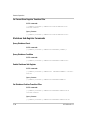
Acronyms
Acronym
Definition
APG
Analog Programming
AUX
Auxiliary
ENET
Ethernet
ISOL
Isolated Analog Programming
OTP
Over Temperature Protection
OVP
Over Voltage Protection
PSU
Power Supply Unit
TVS
Transient Voltage Suppressor
UVP
Under Voltage Protection
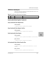
Font Conventions
This Manual uses the following typographical conventions:
vi
7 segment
For display and readback information on the
output voltage and current displays.
Command body text
Represents SCPI commands.
975-0200-01-01
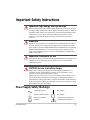
Important Safety Instructions
WARNING: High energy and high voltage
Exercise caution when using a power supply. High energy levels can be stored at
the output voltage terminals on a power supply in normal operation. In addition,
potentially lethal voltages exist in the power circuit and on the output and sense
connectors of a power supply with a rated output greater than 40 V. Filter
capacitors store potentially dangerous energy for some time after power is
removed.
WARNING
Operate the power supply in an environment free of flammable gases or fumes.
To ensure that the power supply's safety features are not compromised, use the
power supply as specified in this Manual and do not substitute parts or make any
unauthorized modifications. If service is necessary, please return the power
supply to the Authorized Service Center. See “Return Material Authorization
Policy” on page WA–3.
WARNING: Limitations on use
The XTR 850 Watt and 1700 Watt Series Programmable DC Power Supply is not
intended for use in connection with life support systems or other medical
equipment or devices.
CAUTION: For use as a battery charger
When you are using a power supply for battery charging applications, it is
essential to provide an appropriately sized fuse or circuit breaker in series
between the power supply output and the battery.
Installation of a protector (fuse or DC circuit breaker), rated for about 115% of
the maximum current rating of the power supply and designed specifically to
interrupt the DC voltage of the battery, will provide adequate current protection.
Where several power supplies are in parallel, it is best to fuse each power supply
rather than use one fuse at the battery.
Power Supply Safety Markings
975-0200-01-01
Alternating Current
On (Supply)
Earth (Ground) Terminal
Off (Supply)
Protective Conductor
Terminal
Caution (Check the Manual
for additional information.)
vii
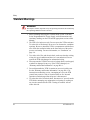
Safety
Standard Warnings
WARNING
This chapter contains important safety and operating instructions. Read and keep
this Operating Manual for future reference.
1. Before installing and using the XTR 850 Watt or XTR 1700 Watt
Series Programmable DC Power Supply, read all instructions and
cautionary markings on the XTR and all appropriate sections of this
Manual.
2. The XTR is for indoor use only. Do not expose the XTR to moisture.
To reduce risk of fire hazard, do not cover or obstruct the ventilation
openings. Be sure to install the XTR in a compartment which allows
air to reach the ventilation inlets on the front and rear of the unit to
prevent overheating. For more information, see “Ventilation” on
page 2–4.
3. To avoid a risk of fire and electric shock, make sure that the existing
wiring is in good condition and the wire is not undersized. Do not
operate the XTR with damaged or substandard wiring.
4. Do not operate the XTR if it has received a sharp blow, been dropped,
or otherwise damaged in any way. If the XTR is damaged, see
“Warranty and Product Information” on page WA–1.
5. Do not disassemble the XTR. It contains no user-serviceable parts.
See the “Warranty and Product Information” on page WA–1 for
instructions on obtaining service. Attempting to service the XTR
yourself may result in a risk of electrical shock or fire. Internal
capacitors remain charged after all power is disconnected.
6. To reduce the risk of electrical shock, disconnect AC power from the
XTR before attempting any maintenance or cleaning or working on
any circuits connected to the XTR. Turning off controls will not
reduce this risk.
viii
975-0200-01-01
Contents
Important Safety Instructions - - - - - - - - - - - - - - - - - - - - - - - - - - - - - - - - -
vii
1 Introduction
Features and Options - - - - - - - - - - - - - - - - - - - - - - - - - - - - - - - - - - - - - - - - - - -1–2
XTR 850 Watt and XTR 1700 Watt Models - - - - - - - - - - - - - - - - - - - - - - - - - - - -1–3
Front Panel for XTR 850 Watt and XTR 1700 Watt - - - - - - - - - - - - - - - - - - - - - -1–4
Front Panel Display and Controls - - - - - - - - - - - - - - - - - - - - - - - - - - - - - - - -1–5
Rear Panel Connectors on XTR 850 Watt - - - - - - - - - - - - - - - - - - - - - - - - - - - - -1–6
Rear Panel Connectors on XTR 1700 Watt- - - - - - - - - - - - - - - - - - - - - - - - - - - - -1–8
2 Installation
Basic Setup Procedure - - - - - - - - - - - - - - - - - - - - - - - - - - - - - - - - - - - - - - - - - -2–2
Step 1: Inspecting and Cleaning - - - - - - - - - - - - - - - - - - - - - - - - - - - - - - - - - - - -2–3
Initial Inspection - - - - - - - - - - - - - - - - - - - - - - - - - - - - - - - - - - - - - - - - - - - -2–3
Periodic Cleaning - - - - - - - - - - - - - - - - - - - - - - - - - - - - - - - - - - - - - - - - - - -2–3
Step 2: Location and Mounting - - - - - - - - - - - - - - - - - - - - - - - - - - - - - - - - - - - -2–4
Rack Mounting - - - - - - - - - - - - - - - - - - - - - - - - - - - - - - - - - - - - - - - - - - - -2–4
Purchasing Rack Mount Kits - - - - - - - - - - - - - - - - - - - - - - - - - - - - - - - - - - -2–4
Ventilation - - - - - - - - - - - - - - - - - - - - - - - - - - - - - - - - - - - - - - - - - - - - - - -2–4
Step 3: Connecting AC Input Power - - - - - - - - - - - - - - - - - - - - - - - - - - - - - - - - -2–5
XTR 850 Watt AC Input Connector - - - - - - - - - - - - - - - - - - - - - - - - - - - - - - -2–5
XTR 1700 Watt AC Input Connector - - - - - - - - - - - - - - - - - - - - - - - - - - - - - -2–6
XTR 1700 Watt AC Input Wire - - - - - - - - - - - - - - - - - - - - - - - - - - - - - - - - -2–7
XTR 1700 Watt AC Input Wire Connection - - - - - - - - - - - - - - - - - - - - - - - - -2–7
Step 4: Selecting Load Wires - - - - - - - - - - - - - - - - - - - - - - - - - - - - - - - - - - - - - -2–9
Load Wiring - - - - - - - - - - - - - - - - - - - - - - - - - - - - - - - - - - - - - - - - - - - - - -2–9
Step 5: Performing Functional Tests - - - - - - - - - - - - - - - - - - - - - - - - - - - - - - - - 2–11
Powering the Power Supply On/Off - - - - - - - - - - - - - - - - - - - - - - - - - - - - - - 2–11
Voltage and Current Mode Operation Checks - - - - - - - - - - - - - - - - - - - - - - - 2–12
Step 6: Connecting Loads - - - - - - - - - - - - - - - - - - - - - - - - - - - - - - - - - - - - - - - 2–13
DC Output Connectors - - - - - - - - - - - - - - - - - - - - - - - - - - - - - - - - - - - - - - 2–13
Inductive Loads - - - - - - - - - - - - - - - - - - - - - - - - - - - - - - - - - - - - - - - - - - - 2–14
975-0200-01-01
ix
Contents
Connecting Single Loads - - - - - - - - - - - - - - - - - - - - - - - - - - - - - - - - - - - - - 2–14
Connecting Multiple Loads - - - - - - - - - - - - - - - - - - - - - - - - - - - - - - - - - - - 2–15
Step 7: Connecting Remote Sensing - - - - - - - - - - - - - - - - - - - - - - - - - - - - - - - - 2–16
3 Local Operation
Introduction - - - - - - - - - - - - - - - - - - - - - - - - - - - - - - - - - - - - - - - - - - - - - - - - -3–2
Configuring Settings from the Front Panel - - - - - - - - - - - - - - - - - - - - - - - - - - - - -3–2
Using the 9-Position Mode Control Knob - - - - - - - - - - - - - - - - - - - - - - - - - - -3–2
Using the Rotary knob/Enter button - - - - - - - - - - - - - - - - - - - - - - - - - - - - - - -3–2
Coarse and Fine Adjustment Modes - - - - - - - - - - - - - - - - - - - - - - - - - - - - - - -3–2
Navigating the Menu System - - - - - - - - - - - - - - - - - - - - - - - - - - - - - - - - - - - - - -3–4
Setting VOL and CUR Modes - - - - - - - - - - - - - - - - - - - - - - - - - - - - - - - - - -3–4
Normal Display Mode and Inactivity Timeout - - - - - - - - - - - - - - - - - - - - - - - -3–6
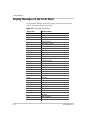
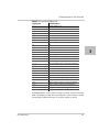
Display Messages on the Front Panel - - - - - - - - - - - - - - - - - - - - - - - - - - - - - - - -3–8
Standard Operation- - - - - - - - - - - - - - - - - - - - - - - - - - - - - - - - - - - - - - - - - - - - 3–10
Operating Modes - - - - - - - - - - - - - - - - - - - - - - - - - - - - - - - - - - - - - - - - - - 3–10
Shipped Configuration (Local Operation) - - - - - - - - - - - - - - - - - - - - - - - - - - 3–14
Turning the Output On/Off - - - - - - - - - - - - - - - - - - - - - - - - - - - - - - - - - - - - - - 3–14
Turning the Auxiliary Output On/Off - - - - - - - - - - - - - - - - - - - - - - - - - - - - - - - 3–15
Output Auto Start Mode (Auto Restart) - - - - - - - - - - - - - - - - - - - - - - - - - - - - - - 3–15
Auxiliary Auto Start Mode - - - - - - - - - - - - - - - - - - - - - - - - - - - - - - - - - - - - - - 3–16
Alarms and Errors - - - - - - - - - - - - - - - - - - - - - - - - - - - - - - - - - - - - - - - - - - - - 3–17
Clearing Alarms - - - - - - - - - - - - - - - - - - - - - - - - - - - - - - - - - - - - - - - - - - - 3–18
Front Panel ALARM LED - - - - - - - - - - - - - - - - - - - - - - - - - - - - - - - - - - - - 3–19
Alarm Masking - - - - - - - - - - - - - - - - - - - - - - - - - - - - - - - - - - - - - - - - - - - 3–20
Alarm Output Latching - - - - - - - - - - - - - - - - - - - - - - - - - - - - - - - - - - - - - - 3–21
Setting Foldback Mode - - - - - - - - - - - - - - - - - - - - - - - - - - - - - - - - - - - - - - - - - 3–22
Resetting Activated Foldback Protection - - - - - - - - - - - - - - - - - - - - - - - - - - 3–23
Using Over Voltage Protection (OVP)- - - - - - - - - - - - - - - - - - - - - - - - - - - - - - - 3–24
Defining the OVP Set Point - - - - - - - - - - - - - - - - - - - - - - - - - - - - - - - - - - - 3–24
Using Under Voltage Protection (UVP) - - - - - - - - - - - - - - - - - - - - - - - - - - - - - - 3–25
Defining the UVP Set Point - - - - - - - - - - - - - - - - - - - - - - - - - - - - - - - - - - - 3–25
Over Current Protection (OCP) - - - - - - - - - - - - - - - - - - - - - - - - - - - - - - - - - - - 3–25
Using Over Temperature Protection Lock (OTP) - - - - - - - - - - - - - - - - - - - - - - - 3–26
Defining the OTP Mode - - - - - - - - - - - - - - - - - - - - - - - - - - - - - - - - - - - - - 3–26
Resetting in Latch Mode - - - - - - - - - - - - - - - - - - - - - - - - - - - - - - - - - - - - - 3–26
x
975-0200-01-01
Contents
Current Configuration Memory Settings - - - - - - - - - - - - - - - - - - - - - - - - - - - - - 3–27
User Setting Memory Locations - - - - - - - - - - - - - - - - - - - - - - - - - - - - - - - - - - - 3–28
Saving User Setting Memory Locations - - - - - - - - - - - - - - - - - - - - - - - - - - - 3–28
Recalling User Setting Memory Locations - - - - - - - - - - - - - - - - - - - - - - - - - 3–29
Local Lockout - - - - - - - - - - - - - - - - - - - - - - - - - - - - - - - - - - - - - - - - - - - - - - - 3–30
Enabling Local Lockout - - - - - - - - - - - - - - - - - - - - - - - - - - - - - - - - - - - - - - 3–30
Disabling Local Lockout - - - - - - - - - - - - - - - - - - - - - - - - - - - - - - - - - - - - - 3–30
Using the External Shutdown Function - - - - - - - - - - - - - - - - - - - - - - - - - - - - - - 3–31
Activating the External Shutdown Function - - - - - - - - - - - - - - - - - - - - - - - - 3–31
Controlling the External Shutdown Function - - - - - - - - - - - - - - - - - - - - - - - - 3–31
Defining the Polarity of the External Shutdown Signal - - - - - - - - - - - - - - - - - 3–31
Interlock Function - - - - - - - - - - - - - - - - - - - - - - - - - - - - - - - - - - - - - - - - - - - - 3–33
Defining the Interlock Mode - - - - - - - - - - - - - - - - - - - - - - - - - - - - - - - - - - - 3–33
Power On Status Signal - - - - - - - - - - - - - - - - - - - - - - - - - - - - - - - - - - - - - - 3–33
Hardware Malfunction Alarms - - - - - - - - - - - - - - - - - - - - - - - - - - - - - - - - - - - - 3–34
Resetting the Power Supply - - - - - - - - - - - - - - - - - - - - - - - - - - - - - - - - - - - - - - 3–35
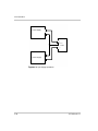
Using Multiple Power Supplies - - - - - - - - - - - - - - - - - - - - - - - - - - - - - - - - - - - 3–37
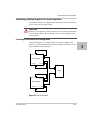
Configuring Multiple Supplies for Series Operation - - - - - - - - - - - - - - - - - - - 3–39
Configuring Multiple Supplies for Current Sharing Operation (APG Method) - 3–41
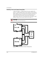
Connecting to the Load in Local Sensing Mode (Parallel Control Method) - - - 3–43
Connecting to the Load in Remote Sensing Mode (Parallel Control Method) - - 3–44
4 Analog Programming (APG) and Isolated Analog Programming
(ISOL)
Introduction - - - - - - - - - - - - - - - - - - - - - - - - - - - - - - - - - - - - - - - - - - - - - - - - -4–2
Analog Programming (APG) of Output Voltage and Output Current - - - - - - - - -4–2
Remote Programming Options - - - - - - - - - - - - - - - - - - - - - - - - - - - - - - - - - -4–3
Analog Programming (APG) Connector J1 - - - - - - - - - - - - - - - - - - - - - - - - - -4–5
Analog Programming Mode- - - - - - - - - - - - - - - - - - - - - - - - - - - - - - - - - - - - - - -4–9
Analog Programming With External Voltage Source - - - - - - - - - - - - - - - - - - -4–9
Voltage-Controlled Voltage APG Setup - - - - - - - - - - - - - - - - - - - - - - - - - - - 4–10
Voltage-Controlled Current APG Setup - - - - - - - - - - - - - - - - - - - - - - - - - - - 4–12
Resistive-Controlled Voltage APG Setup - - - - - - - - - - - - - - - - - - - - - - - - - - 4–15
Resistive-Controlled Current APG Setup - - - - - - - - - - - - - - - - - - - - - - - - - - 4–17
Voltage and Current Readback - - - - - - - - - - - - - - - - - - - - - - - - - - - - - - - - - 4–18
Isolated Analog Programming Mode (ISOL) - - - - - - - - - - - - - - - - - - - - - - - - - - 4–19
AUX Output and Isolated Analog Programming (ISOL) Connector - - - - - - - - 4–19
xi
975-0200-01-01
Contents
Voltage-Controlled Voltage ISOL Setup - - - - - - - - - - - - - - - - - - - - - - - - - - 4–22
Voltage-Controlled Current ISOL Setup - - - - - - - - - - - - - - - - - - - - - - - - - - - 4–23
Resistive-Controlled Voltage ISOL Setup - - - - - - - - - - - - - - - - - - - - - - - - - - 4–26
Resistive-Controlled Current ISOL Setup - - - - - - - - - - - - - - - - - - - - - - - - - - 4–27
Voltage and Current Readback (Isolated) - - - - - - - - - - - - - - - - - - - - - - - - - - - - - 4–29
5 Remote Operation
Introduction - - - - - - - - - - - - - - - - - - - - - - - - - - - - - - - - - - - - - - - - - - - - - - - - -5–2
Hardware and Connection Setup- - - - - - - - - - - - - - - - - - - - - - - - - - - - - - - - - - - -5–2
Configuring Remote Control Using RS-232 - - - - - - - - - - - - - - - - - - - - - - - - -5–2
Configuring Remote Control Using RS-485 - - - - - - - - - - - - - - - - - - - - - - - - -5–7
Configuring Remote Control using the USB Connector - - - - - - - - - - - - - - - - -5–9
Setting Up the PC to Use the USB Connection - - - - - - - - - - - - - - - - - - - - - - -5–9
Ethernet (ENET) or GPIB Connector (Optional) - - - - - - - - - - - - - - - - - - - - - 5–14
Multiple Power Supply Connections to RS-485 Bus - - - - - - - - - - - - - - - - - - - 5–15
Multiple Power Supply Connections to ENET - - - - - - - - - - - - - - - - - - - - - - - 5–16
Terminal Configuration- - - - - - - - - - - - - - - - - - - - - - - - - - - - - - - - - - - - - - - - - 5–17
Data Format - - - - - - - - - - - - - - - - - - - - - - - - - - - - - - - - - - - - - - - - - - - - - - 5–17
End of Message - - - - - - - - - - - - - - - - - - - - - - - - - - - - - - - - - - - - - - - - - - - 5–17
HyperTerminal - - - - - - - - - - - - - - - - - - - - - - - - - - - - - - - - - - - - - - - - - - - - 5–17
Selecting the Appropriate Communication Port - - - - - - - - - - - - - - - - - - - - - - 5–20
Multichannel Address Setting - - - - - - - - - - - - - - - - - - - - - - - - - - - - - - - - - - 5–21
Remote Interface Addressing - - - - - - - - - - - - - - - - - - - - - - - - - - - - - - - - - - 5–21
Multichannel Commands Explained - - - - - - - - - - - - - - - - - - - - - - - - - - - - - 5–22
Status Reporting in SCPI - - - - - - - - - - - - - - - - - - - - - - - - - - - - - - - - - - - - - 5–23
Status Registers Model from IEEE 488.2 - - - - - - - - - - - - - - - - - - - - - - - - - - - - - 5–25
Status Byte - - - - - - - - - - - - - - - - - - - - - - - - - - - - - - - - - - - - - - - - - - - - - - - - - 5–26
Error/Event Queue (ERR) - - - - - - - - - - - - - - - - - - - - - - - - - - - - - - - - - - - - 5–26
Questionable Status Register Summary (QSR) - - - - - - - - - - - - - - - - - - - - - - 5–26
Message Available (MAV) - - - - - - - - - - - - - - - - - - - - - - - - - - - - - - - - - - - - 5–27
Standard Event Status Summary (ESB) - - - - - - - - - - - - - - - - - - - - - - - - - - - 5–27
Master Summary Status (MSS) - - - - - - - - - - - - - - - - - - - - - - - - - - - - - - - - - 5–27
Request Service (RQS) - - - - - - - - - - - - - - - - - - - - - - - - - - - - - - - - - - - - - - 5–27
Operation Status Register Summary (OSR) - - - - - - - - - - - - - - - - - - - - - - - - - 5–27
Standard Event Status Register (SESR) - - - - - - - - - - - - - - - - - - - - - - - - - - - 5–29
xii
975-0200-01-01
Contents
Standard SCPI Register Structure - - - - - - - - - - - - - - - - - - - - - - - - - - - - - - - - - - 5–32
OPERation Status Register - - - - - - - - - - - - - - - - - - - - - - - - - - - - - - - - - - - - - - 5–33
Current SHare Sub-Register - - - - - - - - - - - - - - - - - - - - - - - - - - - - - - - - - - - 5–35
Operation Status Register Commands - - - - - - - - - - - - - - - - - - - - - - - - - - - - 5–36
Current Sharing Sub-Register Commands - - - - - - - - - - - - - - - - - - - - - - - - - - 5–37
Shutdown Sub-Register Commands - - - - - - - - - - - - - - - - - - - - - - - - - - - - - - 5–38
Protection Sub-Register Commands - - - - - - - - - - - - - - - - - - - - - - - - - - - - - - 5–39
QUEStionable Status Register - - - - - - - - - - - - - - - - - - - - - - - - - - - - - - - - - - - - 5–40
VOLTage Sub-Register - - - - - - - - - - - - - - - - - - - - - - - - - - - - - - - - - - - - - - 5–42
TEMPerature Sub-Register - - - - - - - - - - - - - - - - - - - - - - - - - - - - - - - - - - - 5–43
Questionable Status Register Commands - - - - - - - - - - - - - - - - - - - - - - - - - - 5–43
Voltage Status Register Commands - - - - - - - - - - - - - - - - - - - - - - - - - - - - - - 5–44
Temperature Status Register Commands - - - - - - - - - - - - - - - - - - - - - - - - - - 5–45
SCPI Error/Event Queue - - - - - - - - - - - - - - - - - - - - - - - - - - - - - - - - - - - - - - - - 5–46
Reset Command - - - - - - - - - - - - - - - - - - - - - - - - - - - - - - - - - - - - - - - - - - - 5–48
Clear All Status Registers - - - - - - - - - - - - - - - - - - - - - - - - - - - - - - - - - - - - 5–49
SCPI Preset Status - - - - - - - - - - - - - - - - - - - - - - - - - - - - - - - - - - - - - - - - - 5–49
Command Line Help System - - - - - - - - - - - - - - - - - - - - - - - - - - - - - - - - - - 5–50
Locking and Unlocking the Front Panel - - - - - - - - - - - - - - - - - - - - - - - - - - - - - - 5–55
Auto Sequence Programming - - - - - - - - - - - - - - - - - - - - - - - - - - - - - - - - - - 5–55
Configure Other Protection Mechanisms - - - - - - - - - - - - - - - - - - - - - - - - - - - - - 5–62
Foldback Protection - - - - - - - - - - - - - - - - - - - - - - - - - - - - - - - - - - - - - - - - 5–62
Over Temperature Protection - - - - - - - - - - - - - - - - - - - - - - - - - - - - - - - - - - 5–63
Interlock Enable/Disable - - - - - - - - - - - - - - - - - - - - - - - - - - - - - - - - - - - - - 5–63
Save and Recall - - - - - - - - - - - - - - - - - - - - - - - - - - - - - - - - - - - - - - - - - - - 5–64
Set Analog Programming Level - - - - - - - - - - - - - - - - - - - - - - - - - - - - - - - - 5–64
Set Remote Programming Interface - - - - - - - - - - - - - - - - - - - - - - - - - - - - - - 5–65
Protection Mask (Enable Alarms) - - - - - - - - - - - - - - - - - - - - - - - - - - - - - - - 5–65
6 Calibration and Troubleshooting
Introduction - - - - - - - - - - - - - - - - - - - - - - - - - - - - - - - - - - - - - - - - - - - - - - - - -6–2
Main Voltage and Current Calibration Principle - - - - - - - - - - - - - - - - - - - - - - - - -6–2
Understanding the Problem - - - - - - - - - - - - - - - - - - - - - - - - - - - - - - - - - - - -6–2
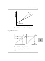
Step 1: Gain Calibration - - - - - - - - - - - - - - - - - - - - - - - - - - - - - - - - - - - - - -6–3
Step 2: Offset Calibration - - - - - - - - - - - - - - - - - - - - - - - - - - - - - - - - - - - - - -6–4
Step 3: Recalibrate Gain - - - - - - - - - - - - - - - - - - - - - - - - - - - - - - - - - - - - - -6–4
xiii
975-0200-01-01
Contents
Calibrating the Output Voltage- - - - - - - - - - - - - - - - - - - - - - - - - - - - - - - - - - - - -6–5
Gain Calibration - - - - - - - - - - - - - - - - - - - - - - - - - - - - - - - - - - - - - - - - - - - -6–5
Offset Calibration - - - - - - - - - - - - - - - - - - - - - - - - - - - - - - - - - - - - - - - - - - -6–5
Calibrating the Output Current - - - - - - - - - - - - - - - - - - - - - - - - - - - - - - - - - - - - -6–6
Gain Calibration - - - - - - - - - - - - - - - - - - - - - - - - - - - - - - - - - - - - - - - - - - - -6–6
Offset Calibration - - - - - - - - - - - - - - - - - - - - - - - - - - - - - - - - - - - - - - - - - - -6–6
Over Voltage Protection Calibration - - - - - - - - - - - - - - - - - - - - - - - - - - - - - - - - -6–7
Non-isolated Analog Programming Calibration- - - - - - - - - - - - - - - - - - - - - - - - - -6–8
Non-isolated Voltage Monitoring Calibration - - - - - - - - - - - - - - - - - - - - - - - -6–8
Non-isolated Current Monitoring Calibration - - - - - - - - - - - - - - - - - - - - - - - -6–9
Non-isolated Voltage Programming of Voltage Calibration - - - - - - - - - - - - - - -6–9
Non-isolated Resistive Programming of Voltage Calibration - - - - - - - - - - - - - 6–10
Non-isolated Voltage Programming of Current Calibration - - - - - - - - - - - - - - 6–11
Non-isolated Resistive Programming of Current Calibration - - - - - - - - - - - - - 6–11
Calibration Procedure for Isolated Modes - - - - - - - - - - - - - - - - - - - - - - - - - - - - 6–13
Isolated Voltage Monitoring Calibration - - - - - - - - - - - - - - - - - - - - - - - - - - - 6–13
Isolated Current Monitoring Calibration - - - - - - - - - - - - - - - - - - - - - - - - - - - 6–13
Isolated Voltage Programming of Voltage Calibration - - - - - - - - - - - - - - - - - 6–14
Isolated Resistive Programming of Voltage Calibration - - - - - - - - - - - - - - - - 6–15
Isolated Voltage Programming of Current Calibration - - - - - - - - - - - - - - - - - 6–16
Isolated Resistive Programming of Current Calibration - - - - - - - - - - - - - - - - - 6–16
Storing and Loading Calibration Parameters- - - - - - - - - - - - - - - - - - - - - - - - - - - 6–17
Restore Factory Calibration - - - - - - - - - - - - - - - - - - - - - - - - - - - - - - - - - - - - - - 6–18
User Diagnostics - - - - - - - - - - - - - - - - - - - - - - - - - - - - - - - - - - - - - - - - - - - - - 6–18
Emergency Shutdown - - - - - - - - - - - - - - - - - - - - - - - - - - - - - - - - - - - - - - - 6–18
Unusual or Erratic Operation - - - - - - - - - - - - - - - - - - - - - - - - - - - - - - - - - - 6–19
Troubleshooting for Operators - - - - - - - - - - - - - - - - - - - - - - - - - - - - - - - - - 6–19
A
SCPI Command Reference
SCPI Conformance Information - - - - - - - - - - - - - - - - - - - - - - - - - - - - - - - - - - - A–2
IEEE 488.2/SCPI Syntax and Style - - - - - - - - - - - - - - - - - - - - - - - - - - - - - - A–2
SCPI Command Hierarchy - - - - - - - - - - - - - - - - - - - - - - - - - - - - - - - - - - - - A–3
Using SCPI Commands - - - - - - - - - - - - - - - - - - - - - - - - - - - - - - - - - - - - - - A–4
Parameter Types - - - - - - - - - - - - - - - - - - - - - - - - - - - - - - - - - - - - - - - - - - - A–6
SPCI Command Tree - - - - - - - - - - - - - - - - - - - - - - - - - - - - - - - - - - - - - - - - - - A–8
SCPI Command Summary - - - - - - - - - - - - - - - - - - - - - - - - - - - - - - - - - - - A–14
xiv
975-0200-01-01
Contents
B
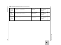
Error Messages
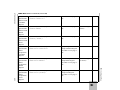
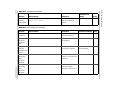
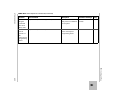
Error Messages - - - - - - - - - - - - - - - - - - - - - - - - - - - - - - - - - - - - - - - - - - - - - Command Error List - - - - - - - - - - - - - - - - - - - - - - - - - - - - - - - - - - - - - - - Execution Error List - - - - - - - - - - - - - - - - - - - - - - - - - - - - - - - - - - - - - - - Device-Specific Error List - - - - - - - - - - - - - - - - - - - - - - - - - - - - - - - - - - - Query Error List - - - - - - - - - - - - - - - - - - - - - - - - - - - - - - - - - - - - - - - - - - -
C
B–2
B–2
B–3
B–4
B–5
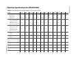
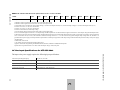
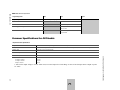
Specifications
Electrical Specifications for XTR 850 Watt - - - - - - - - - - - - - - - - - - - - - - - - - - AC Line Input Specifications for XTR 850 Watt - - - - - - - - - - - - - - - - - - - - Electrical Specifications for XTR 1700 Watt - - - - - - - - - - - - - - - - - - - - - - - - - AC Line Input Specifications for XTR 1700 Watt - - - - - - - - - - - - - - - - - - - Remote Operation - - - - - - - - - - - - - - - - - - - - - - - - - - - - - - - - - - - - - - - - - - - Common Specifications for All Models - - - - - - - - - - - - - - - - - - - - - - - - - - - - - -
Warranty and Product Information
C–2
C–3
C–4
C–5
C–6
C–7
- - - - - - - - - - - - - - - - - - - - - - - - - -WA–1
Index - - - - - - - - - - - - - - - - - - - - - - - - - - - - - - - - - - - - - - - - - - - - - - - - - - - - - - - IX–1
xv
975-0200-01-01
xvi
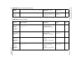
Figures
Figure 1-1
Figure 1-2
Figure 1-3
Figure 1-4
Figure 1-5
Figure 1-6
Figure 1-7
Figure 2-1
Figure 2-2
Figure 2-3
Figure 2-4
Figure 3-1
Figure 3-2
Figure 3-3
Figure 3-4
Figure 3-5
Figure 3-6
Figure 3-7
Figure 3-8
Figure 4-1
Figure 4-2
Figure 4-3
Figure 4-4
Figure 4-5
Figure 4-6
Figure 4-7
Figure 4-8
Figure 4-9
Figure 4-10
Figure 4-11
Figure 4-12
Figure 4-13
Front Panel: XTR 850 Watt and XTR 1700 Watt - - - - - - - - - - - - - - - - - 1–4
Front Panel Display and Controls - - - - - - - - - - - - - - - - - - - - - - - - - - - - 1–5
XTR 850 Watt Series: 6 V to 40 V Models - - - - - - - - - - - - - - - - - - - - - 1–6
XTR 850 Watt Series: 60 V to 150 V Models- - - - - - - - - - - - - - - - - - - - 1–6
XTR 850 Watt Series: 300 V to 600 V Models - - - - - - - - - - - - - - - - - - - 1–6
XTR 1700 Watt Series: 6 V to 40 V Models - - - - - - - - - - - - - - - - - - - - 1–8
XTR 1700 Watt Series: 60 V to 600 V Models - - - - - - - - - - - - - - - - - - - 1–8
XTR 1700 Watt AC Input Cover and Strain Relief - - - - - - - - - - - - - - - - 2–6
Maximum Load Wire Length for 1 V Line Drop- - - - - - - - - - - - - - - - - 2–10
Connecting Single Loads - - - - - - - - - - - - - - - - - - - - - - - - - - - - - - - - 2–14
Remote Sense Connection- - - - - - - - - - - - - - - - - - - - - - - - - - - - - - - - 2–16
9 Position Mode Control Knob - - - - - - - - - - - - - - - - - - - - - - - - - - - - - 3–2
Front Panel Menu System - - - - - - - - - - - - - - - - - - - - - - - - - - - - - - - - - 3–7
Operating Modes - - - - - - - - - - - - - - - - - - - - - - - - - - - - - - - - - - - - - - 3–12
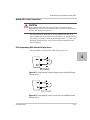
Split Supply Operation - - - - - - - - - - - - - - - - - - - - - - - - - - - - - - - - - - 3–38
Series Operation - - - - - - - - - - - - - - - - - - - - - - - - - - - - - - - - - - - - - - 3–39
Load Connections in Remote Sensing Mode - - - - - - - - - - - - - - - - - - - 3–40
Load Connections in Local Sensing Mode - - - - - - - - - - - - - - - - - - - - - 3–43
Load Connections in Remote Sensing Mode (Parallel Control Method) - 3–44
APG Connector Terminals - - - - - - - - - - - - - - - - - - - - - - - - - - - - - - - - 4–5
Inserting Screwdriver into Spring Terminal Block - - - - - - - - - - - - - - - - 4–7
APG and DC Output Connector - - - - - - - - - - - - - - - - - - - - - - - - - - - - - 4–7
Programming Output Voltage using an External Voltage Source - - - - - - - 4–9
Programming Output Current using an External Voltage Source - - - - - - - 4–9
Programming Output Voltage using an External Resistor - - - - - - - - - - - 4–14
Programming Output Current using an External Resistor - - - - - - - - - - - 4–14
Voltage Readback Using APG Connector J1 - - - - - - - - - - - - - - - - - - - 4–18
Current Readback Using APG Connector J1 - - - - - - - - - - - - - - - - - - - 4–18
AUX Output and ISOL Connector Pinout - - - - - - - - - - - - - - - - - - - - - 4–19
Programming Output Voltage using an Isolated External Voltage Source 4–21
Programming Output Current using an Isolated External Voltage Source 4–21
Programming Output Voltage using an Isolated External Resistor - - - - - 4–25
975-0200-01-01
xvii
Figures
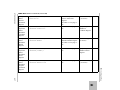
Figure 4-14
Figure 4-15
Figure 4-16
Figure 5-1
Figure 5-2
Figure 5-3
Figure 5-4
Figure 5-5
Figure 5-6
Figure 5-7
Figure 5-8
Figure 5-9
Figure 5-10
Figure 5-11
Figure 5-12
Figure 5-13
Figure 5-14
Figure 5-15
Figure 5-16
Figure 5-17
Figure 5-18
Figure 5-19
Figure 5-20
Figure 5-21
Figure 5-22
Figure 5-23
Figure 6-1
Figure 6-2
Figure 6-3
Figure 6-4
Figure C-1
Figure C-2
Figure C-3
Figure C-4
Figure C-5
Programming Output Current using an Isolated External Resistor - - - - - 4–25
Isolated Voltage Monitoring - - - - - - - - - - - - - - - - - - - - - - - - - - - - - - 4–29
Isolated Current Monitoring - - - - - - - - - - - - - - - - - - - - - - - - - - - - - - 4–29
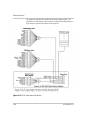
Remote Control Connectors - - - - - - - - - - - - - - - - - - - - - - - - - - - - - - - 5–3
DB-9 Pinout - - - - - - - - - - - - - - - - - - - - - - - - - - - - - - - - - - - - - - - - - - 5–4
RS-232 Communication Cable with DB-9 Pinout - - - - - - - - - - - - - - - - - 5–5
DB-25 Pinout - - - - - - - - - - - - - - - - - - - - - - - - - - - - - - - - - - - - - - - - - 5–5
RS-232 Communication Cable with DB-25 Pinout - - - - - - - - - - - - - - - - 5–6
RS-485 Communication Cable with DB-9 - - - - - - - - - - - - - - - - - - - - - - 5–8
RS-485 Communication Cable from Master to Slave Unit - - - - - - - - - - - 5–9
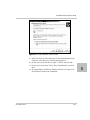
Found New Hardware Wizard - - - - - - - - - - - - - - - - - - - - - - - - - - - - - 5–10
Install Hardware Device Drivers - - - - - - - - - - - - - - - - - - - - - - - - - - - 5–11
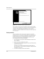
Completing the New Hardware Wizard - - - - - - - - - - - - - - - - - - - - - - - 5–12
Device Manager - - - - - - - - - - - - - - - - - - - - - - - - - - - - - - - - - - - - - - 5–13
Communications Port (COM1) Properties - - - - - - - - - - - - - - - - - - - - - 5–13
Completing the new hardware wizard - - - - - - - - - - - - - - - - - - - - - - - - 5–14
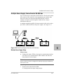
Multi Power Supply Connection to RS-485 Bus - - - - - - - - - - - - - - - - - 5–15
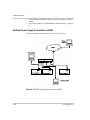
Multi Power Supply Connection to ENET - - - - - - - - - - - - - - - - - - - - - 5–16
USB Settings - - - - - - - - - - - - - - - - - - - - - - - - - - - - - - - - - - - - - - - - 5–18
ASCII Setup - - - - - - - - - - - - - - - - - - - - - - - - - - - - - - - - - - - - - - - - - 5–19
SCPI Status Reporting Model - - - - - - - - - - - - - - - - - - - - - - - - - - - - - 5–24
IEEE 488.2 Register Model- - - - - - - - - - - - - - - - - - - - - - - - - - - - - - - 5–25
Summary of Standard Event Status Register - - - - - - - - - - - - - - - - - - - 5–30
SCPI Register Model - - - - - - - - - - - - - - - - - - - - - - - - - - - - - - - - - - - 5–32
Operation Status Register Fanout - - - - - - - - - - - - - - - - - - - - - - - - - - - 5–33
SCPI QUEStionable Registers Fanout- - - - - - - - - - - - - - - - - - - - - - - - 5–41
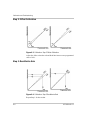
Offset (Intercept) Error and Gain (Slope) Error- - - - - - - - - - - - - - - - - - - 6–3
Calibration: Step 1 Gain Calibration - - - - - - - - - - - - - - - - - - - - - - - - - - 6–3
Calibration: Step 2 Offset Calibration - - - - - - - - - - - - - - - - - - - - - - - - - 6–4
Calibration: Step 3 Recalibrate Gain - - - - - - - - - - - - - - - - - - - - - - - - - - 6–4
XTR 850 Watt Mechanical Dimensions: 6 to 40 V Models - - - - - - - - - - C–9
XTR 850 Watt Mechanical Dimensions: 60 V to 600 V Models - - - - - - C–10
XTR 1700 Watt Mechanical Dimensions: 6 V to 40 V Models - - - - - - - C–11
XTR 1700 Watt Mechanical Dimensions: 6 V to 40 V Models
DC Output Cover
C–12
XTR 1700 Watt Mechanical Dimensions: 60 V to 600 V Models - - - - - C–13
975-0200-01-01
xviii
Tables
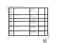
Table 1-1
Table 1-2
Table 2-1
Table 2-2
Table 2-3
Table 3-1
Table 3-2
Table 3-3
Table 3-4
Table 3-5
Table 3-6
Table 3-7
Table 3-8
Table 3-9
Table 4-1
Table 4-2
Table 4-3
Table 4-4
Table 5-1
Table 5-2
Table 5-3
Table 5-4
Table 5-5
Table 5-6
Table 5-7
Table 5-8
Table 5-9
Table 5-10
Table 5-11
Table 5-12
Table 5-13
Table 5-14
XTR 850 Watt Series Voltage and Current Ranges - - - - - - - - - - - - - - - - 1–3
XTR 1700 Watt Series Voltage and Current Ranges - - - - - - - - - - - - - - - 1–3
Basic Setup Procedure - - - - - - - - - - - - - - - - - - - - - - - - - - - - - - - - - - - 2–2
XTR 1700 Watt: Recommended AC Input Wire - - - - - - - - - - - - - - - - - - 2–7
Current Carrying Capacity for Load Wiring - - - - - - - - - - - - - - - - - - - - - 2–9
Select and Set from the Front Panel - - - - - - - - - - - - - - - - - - - - - - - - - - 3–3
Front Panel Display Text - - - - - - - - - - - - - - - - - - - - - - - - - - - - - - - - - 3–8
Shipped Configuration - - - - - - - - - - - - - - - - - - - - - - - - - - - - - - - - - - 3–14
Alarm Order of Precedence - - - - - - - - - - - - - - - - - - - - - - - - - - - - - - - 3–17
Alarm Mask Bit Positions - - - - - - - - - - - - - - - - - - - - - - - - - - - - - - - - 3–20
Alarm Latch Bit Positions - - - - - - - - - - - - - - - - - - - - - - - - - - - - - - - - 3–21
Power Cycle Saved/Recalled Settings - - - - - - - - - - - - - - - - - - - - - - - - 3–27
User Accessible Saved/Recalled Settings- - - - - - - - - - - - - - - - - - - - - - 3–28
Power Supply Default Settings- - - - - - - - - - - - - - - - - - - - - - - - - - - - - 3–35
Monitor Lines - - - - - - - - - - - - - - - - - - - - - - - - - - - - - - - - - - - - - - - - - 4–3
Remote Programming Options- - - - - - - - - - - - - - - - - - - - - - - - - - - - - - 4–4
APG Pins and Functions J1 - - - - - - - - - - - - - - - - - - - - - - - - - - - - - - - - 4–5
AUX Output and ISOL Connector Pins and Functions J3- - - - - - - - - - - 4–20
Remote Control Connector Pins and Functions J4 and J6 - - - - - - - - - - - - 5–3
DB-9 Pinouts - - - - - - - - - - - - - - - - - - - - - - - - - - - - - - - - - - - - - - - - - 5–4
RJ-45 Pinouts - - - - - - - - - - - - - - - - - - - - - - - - - - - - - - - - - - - - - - - - - 5–4
DB-25 Pinouts - - - - - - - - - - - - - - - - - - - - - - - - - - - - - - - - - - - - - - - - 5–5
DB-9 Pinouts - - - - - - - - - - - - - - - - - - - - - - - - - - - - - - - - - - - - - - - - - 5–7
RJ-45 Plug Pinouts - - - - - - - - - - - - - - - - - - - - - - - - - - - - - - - - - - - - - 5–7
RJ-45 Plug on Slave Unit - - - - - - - - - - - - - - - - - - - - - - - - - - - - - - - - - 5–8
Rules for Multichannel Responses - - - - - - - - - - - - - - - - - - - - - - - - - - 5–22
Status Byte Summary Register- - - - - - - - - - - - - - - - - - - - - - - - - - - - - 5–26
Standard Event Status Register - - - - - - - - - - - - - - - - - - - - - - - - - - - - 5–30
OPERation Status Register - - - - - - - - - - - - - - - - - - - - - - - - - - - - - - - 5–34
OPERation SHUTdown Status Register - - - - - - - - - - - - - - - - - - - - - - 5–35
OPERation SHUTdown PROTection Status Register - - - - - - - - - - - - - 5–35
OPERation CSHare Status Register - - - - - - - - - - - - - - - - - - - - - - - - - 5–36
975-0200-01-01
xix
Tables
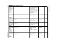
Table 5-15
Table 5-16
Table 5-17
Table 5-18
Table 5-19
Table 6-1
Table A-1
Table A-3
Table A-2
Table A-4
Table A-5
Table A-6
Table A-7
Table A-8
Table A-9
Table A-10
Table A-12
Table A-11
Table B-1
Table B-2
Table B-3
Table B-4
Table C-1
Table C-2
Table C-3
xx
QUEStionable Status Register - - - - - - - - - - - - - - - - - - - - - - - - - - - - - - 5–42
QUEStionable VOLTage Status Register - - - - - - - - - - - - - - - - - - - - - - 5–42
QUEStionable TEMPerature Status Register - - - - - - - - - - - - - - - - - - - - 5–43
Preset Values of User Configurable Registers - - - - - - - - - - - - - - - - - - - 5–50
Alarms Bit Mask - - - - - - - - - - - - - - - - - - - - - - - - - - - - - - - - - - - - - - - 5–66
Troubleshooting - - - - - - - - - - - - - - - - - - - - - - - - - - - - - - - - - - - - - - - 6–19
IEEE 488.2 Commands - - - - - - - - - - - - - - - - - - - - - - - - - - - - - - - - - A–14
SCPI Commands for Output Control - - - - - - - - - - - - - - - - - - - - - - - - A–16
Readback Commands- - - - - - - - - - - - - - - - - - - - - - - - - - - - - - - - - - - A–16
SCPI Commands for Calibration - - - - - - - - - - - - - - - - - - - - - - - - - - - A–18
SCPI Commands to Clear All Protection Mechanisms- - - - - - - - - - - - - A–21
SCPI Commands for Foldback Protection - - - - - - - - - - - - - - - - - - - - - A–21
SCPI Commands for Power - - - - - - - - - - - - - - - - - - - - - - - - - - - - - - A–21
SCPI Commands for Triggering - - - - - - - - - - - - - - - - - - - - - - - - - - - A–22
System Commands - - - - - - - - - - - - - - - - - - - - - - - - - - - - - - - - - - - - A–22
Status Commands - - - - - - - - - - - - - - - - - - - - - - - - - - - - - - - - - - - - - A–26
Auto Sequence Commands - - - - - - - - - - - - - - - - - - - - - - - - - - - - - - - A–34
Protection Commands - - - - - - - - - - - - - - - - - - - - - - - - - - - - - - - - - - A–34
Command Error List - - - - - - - - - - - - - - - - - - - - - - - - - - - - - - - - - - - - B–2
Execution Error List - - - - - - - - - - - - - - - - - - - - - - - - - - - - - - - - - - - - B–3
Device-Specific Error List - - - - - - - - - - - - - - - - - - - - - - - - - - - - - - - - B–4
Query Error List - - - - - - - - - - - - - - - - - - - - - - - - - - - - - - - - - - - - - - - B–5
XTR 850 Watt Electrical Specifications for 6 V to 600 V Models - - - - - - C–2
XTR 1700 Watt Electrical Specifications for 6 V to 600 V Models - - - - - C–4
Remote Operation - - - - - - - - - - - - - - - - - - - - - - - - - - - - - - - - - - - - - - C–6
975-0200-01-01
1
Introduction
Chapter 1, Introduction, describes the features of the XTR
850 Watt and 1700 Watt Series Programmable DC Power
Supply.
Introduction
Features and Options
The XTR 850 Watt and XTR 1700 Watt Series Programmable DC Power
Supplies provide stable, variable output voltage and current for a broad
range of development and system requirements. The power supplies have
a high power density and numerous industry standard interfaces:
•
•
•
•
•
•
•
•
•
•
•
•
•
1-2
RS-232, RS-485, analog programming (APG), isolated analog
programming (ISOL), and USB built-in ports.
Optional GPIB or Ethernet (ENET) control for remote operation and
readback.
Seamlessly switches between front panel and any digital interface
(RS-232, RS-485, USB, GPIB or ENET).
Simultaneous digital displays for both voltage and current.
Front panel control by Rotary knob/Enter button permits high
resolution setting of the output.
Active Power Factor Correction (PFC) reduces input current and
input current harmonics.
Automatic crossover system allows the power supply to switch
operating modes between Constant Current and Constant Voltage
operation.
Multiple units can be connected in parallel or series to produce
greater diversity or for use in higher power applications.
Short-circuit protection of DC outputs provides greater operating
safety.
Built-in APG and ISOL interface provides a galvanically isolated
analog voltage control of the output, master/slave output tracking,
and remote Enable/disable for safety and precision.
Remote output voltage sensing automatically compensates for cable
losses.
Software calibrated.
Three user setting memory locations.
975-0200-01-01
XTR 850 Watt and XTR 1700 Watt Models
XTR 850 Watt and XTR 1700 Watt Models
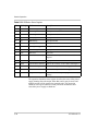
Table 1-1 lists the models in the XTR 850 Watt series covered by this
Manual.
1
Table 1-1 XTR 850 Watt Series Voltage and Current Ranges
Model
Output Voltage
Output Current
6-110
0–6 V
0–110 A
8-100
0–8 V
0–100 A
12-70
0–12 V
0–70 A
20-42
0–20 V
0–42 A
33-25
0–33 V
0–25 A
40-21
0–40 V
0–21 A
60-14
0–60 V
0–14 A
80-10.5
0–80 V
0–10.5 A
100-8.5
0–100 V
0–8.5 A
150-5.6
0–150 V
0–5.6 A
300-2.8
0–300 V
0–2.8 A
600-1.4
0–600 V
0–1.4 A
Table 1-2 lists the models in the XTR 1700 Watt series covered by this
Manual.
Table 1-2 XTR 1700 Watt Series Voltage and Current Ranges
975-0200-01-01
Model
Output Voltage
Output Current
6-220
0–6 V
0–220 A
8-200
0–8 V
0–200 A
12-140
0–12 V
0–140 A
20-84
0–20 V
0–84 A
33-50
0–33 V
0–50 A
40-42
0–40 V
0–42 A
60-28
0–60 V
0–28 A
80-21
0–80 V
0–21 A
100-17
0–100 V
0–17A
150-11.2
0–150 V
0–11.2A
300-5.6
0–300 V
0–5.6 A
600-2.8
0–600 V
0–2.8A
1-3
Introduction
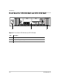
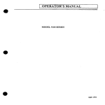
Front Panel for XTR 850 Watt and XTR 1700 Watt
1
2
3
Figure 1-1 Front Panel: XTR 850 Watt and XTR 1700 Watt
Item
Description
1
Front panel power switch
2
Front panel display. See Figure 1-2 for details.
3
Air Intake Vents
1-4
975-0200-01-01
Front Panel for XTR 850 Watt and XTR 1700 Watt
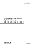
Front Panel Display and Controls
1
1
2
3
4
5
6
7
8
9
Figure 1-2 Front Panel Display and Controls
Item
Description
1
Rotary knob/Enter button
2
Constant Voltage (CV) Mode LED (green)
3
Output Voltage Display
4
Constant Current (CC) Mode LED (green)
5
Output Current Display
6
Alarm Indicator LED (red)
7
OUTPUT ON/OFF button
8
Auxiliary Output ON/OFF (AUX ON/OFF) button
9
9-Position Mode Control Knob. For detailed information, see “Configuring Settings from
the Front Panel” on page 3–2.
975-0200-01-01
1-5
Introduction
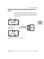
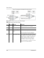
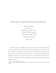
Rear Panel Connectors on XTR 850 Watt
1
6
2
7
3
8
4
9
5
10
11
Figure 1-3 XTR 850 Watt Series: 6 V to 40 V Models
2
1
6
3
7
8
4
9
10
5
11
Figure 1-4 XTR 850 Watt Series: 60 V to 150 V Models
1
6
7
4
3
2
8
9
5
10
11
Figure 1-5 XTR 850 Watt Series: 300 V to 600 V Models
1-6
975-0200-01-01
Rear Panel Connectors on XTR 850 Watt
Item
Description
1
6 V– 40 V Models: DC Output Terminal Positive
60 V–150 V Models: DC Output Connectors Positive (6.5 mm hole diameter)
300 V–600 V Models: DC Output Connectors Positive
2
6 V– 40 V Models: DC Output Terminal Negative
60 V–150 V Models: DC Output Connectors Negative (6.5 mm hole diameter)
300 V–600 V Models: DC Output Connectors Negative
3 (J2)
Ethernet (ENET) or GPIB Connector (optional)
4 (J4)
RS-232/RS-485 Connector In Port
5
AC Input Connector (IEC Type)
6
Chassis Ground Stud
7 (J1)
Analog Programming (APG) Connector. For pin information, see page 4–5.
8 (J3)
AUX Output and Isolated Analog Programming (ISOL) Connector. For pin information, see
page 4–19.
9 (J5)
USB Connector
1
10 (J6) RS-485 Connector Multichannel Port
11
Fan Exhaust Vents
975-0200-01-01
1-7
Introduction
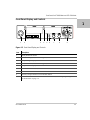
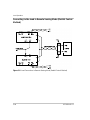
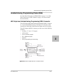
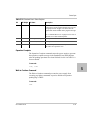
Rear Panel Connectors on XTR 1700 Watt
1
4
3
2
5
100 - 240 Vac
47-63 Hz, 2200 VA
J4
J2
J1
SN
J3
MADE IN CANADA
7
6
J6
J5
8
9
11
10
Figure 1-6 XTR 1700 Watt Series: 6 V to 40 V Models
1
3
2
5
4
100 - 240 Vac
47-63 Hz, 2200 VA
J4
J2
J1
SN
6
7
J3
J6
J5
MADE IN CANADA
8
9
10
11
Figure 1-7 XTR 1700 Watt Series: 60 V to 600 V Models
Item
Description
1
6 V– 40 V Models: DC Output Terminal Positive (8.5 mm hole diameter)
60 V–600 V Models: DC Output Connectors Positive
2
6 V– 40 V Models DC Output Terminal Negative (8.5 mm hole diameter)
60 V–600 V Models: DC Output Connectors Negative
3 (J2)
Ethernet (ENET) or GPIB Connector (optional)
4 (J4)
RS-232/RS-485 Connector In Port
5
AC Input Terminal
6
Chassis Ground Stud
7 (J1)
Analog Programming Connector. For pin information, see page 4–5.
8 (J3)
AUX Output and Isolated Analog Programming Connector. For pin information, see
page 4–19.
9 (J5)
USB Connector
10 (J6) RS-485 Connector Multichannel Port
11
1-8
Fan Exhaust Vents
975-0200-01-01
2
Installation
Chapter 2, Installation, provides information and
procedures for inspecting, installing, and testing the power
supply.
Installation
Basic Setup Procedure
Table 2-1 provides a summary of the basic setup procedure with
references to the relevant sections in this chapter. Refer to this table if you
are unfamiliar with the installation requirements for the power supply.
Complete each step in the sequence given.
Table 2-1 Basic Setup Procedure
Step
Description
Action
Reference
1
Inspect
Inspect the power supply.
“Step 1: Inspecting and Cleaning”
on page 2–3.
2
Install
Install the power supply
(benchtop or rack mount).
Ensure adequate ventilation.
“Step 2: Location and Mounting” on
page 2–4.
3
Connect Input
Power
Connect AC input power.
“Step 3: Connecting AC Input
Power” on page 2–5.
4
Select Wires
Select wires that are correctly
rated for the maximum DC
output current.
“Step 4: Selecting Load Wires” on
page 2–9.
5
Test
Perform functional tests for
voltage mode operation, current
mode operation, and front panel
controls.
“Step 5: Performing Functional
Tests” on page 2–11.
6
Connect Loads
Connect the load wires to the
DC output.
“Step 6: Connecting Loads” on
page 2–13.
7
Connect Remote
Sensing (if
required)
Connect remote sensing
connectors on power supply to
load.
“Step 7: Connecting Remote
Sensing” on page 2–16.
2-2
975-0200-01-01
Step 1: Inspecting and Cleaning
Step 1: Inspecting and Cleaning
Initial Inspection
When you first receive your unit, perform a physical check:
1. Inspect the unit for any scratches and cracks, broken switches,
connectors or displays.
2. For the XTR 850 Watt only, ensure that the packing box contains the
7.5 foot (2.5 m) power cord. (The XTR 1700 Watt is not supplied
with a power cord.)
3. If you see external damage or suspect internal damage, contact
Xantrex Customer Service (see Contact Information on page iii) for
an assessment. If the unit is damaged, save all packing materials and
notify Xantrex Customer Service immediately. See packing
instructions in “Return Procedure” on page WA–4.
Periodic Cleaning
The power supply only requires periodic cleaning, not routine servicing.
Whenever a unit is removed from operation, clean the metal surfaces with
naptha or an equivalent solvent, and clean the front panel with a weak
solution of soap and water. Use low-pressure compressed air to blow dust
from components on the printed circuit boards.
975-0200-01-01
2-3
2
Installation
Step 2: Location and Mounting
The power supply may be rack-mounted or used in benchtop applications.
Rack Mounting
The XTR 850 Watt power supply is designed to fill half of a standard
19 inch (483 mm) equipment rack. The XTR 1700 Watt is designed to fill
a standard 19 inch (483 mm) equipment rack.
Units can be combined with the same models in the 850 W or 1700 W
series for customer applications.
Purchasing Rack Mount Kits
Contact Xantrex Customer Service (see “Contact Information” on
page iii) about purchasing the Rack Mount Kit options for XTR 850 Watt
and XTR 1700 Watt. For a list of the part numbers, see “Part Numbers for
Rack Mount Kits” on page iii. Installation information for the different
rack mount options are provided with the rack mount kits.
For XTR product support, visit www.xantrex.com and navigate to the
XTR home page.
Ventilation
Whether operating the power supply in a rack or on a bench, allow air to
reach the ventilation inlets on the front and rear of the unit for cooling.
The direction of airflow is from the front of the unit to the back of the
unit. Ventilation space is not required at the top, bottom or sides of the
power supply.
2-4
975-0200-01-01
Step 3: Connecting AC Input Power
Step 3: Connecting AC Input Power
WARNING: Shock hazard
Disconnect AC power from the unit before removing the cover. Even with the
front panel power switch in the Off position, live line voltages are exposed when
the cover is removed. Repairs must be made by an Authorized Service Center.
WARNING
There is a potential shock hazard if the power supply chassis and cover are not
connected to an electrical ground via the safety ground in the AC input
connector. Ensure that the power supply is connected to a grounded AC outlet
with the recommended AC input cord configured for the available line voltage as
described in this section.
WARNING
The AC input cord is the disconnect device for the power supply. The plug must
be a non-locking plug which is readily identifiable by and accessible to the
operator. The input cord must be no longer than 9.84 feet (3 m).
XTR 850 Watt AC Input Connector
On the XTR 850 Watt, the AC input connector is a standard IEC 16 A
250 V male connector located on the rear panel of the power supply. The
AC input cord provided is rated for 30 A, 300 V and appropriate for use
in any country.
975-0200-01-01
2-5
2
Installation
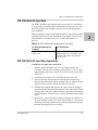
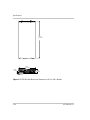
XTR 1700 Watt AC Input Connector
On the XTR 1700 Watt, the AC input connector is a 3-terminal wire
clamp located on the rear panel of the power supply. See Figure 2-1.
AC cover
Screw (1 place)
100 - 240 Vac
47-63 Hz, 2200 VA
AC input terminal
Screw-on locknut
Figure 2-1 XTR 1700 Watt AC Input Cover and Strain Relief
2-6
975-0200-01-01
Step 3: Connecting AC Input Power
XTR 1700 Watt AC Input Wire
The XTR 1700 Watt is not supplied with a power cord or a non-locking
AC plug. Table 2-2 specifies the recommended AC input wire size. You
must also purchase and install the correctly rated non-locking plug for
your installation.
Make sure that the wiring of the product and the AC plug comply with the
applicable local code for your installation. If you require a special cord,
contact Xantrex Customer Service (see “Contact Information” on
page iii).
Table 2-2 XTR 1700 Watt: Recommended AC Input Wire
AC Input Voltage Range and
Frequency
Wire Specifications
85–265 Vac, 47–63 Hz, single
phase 3 wire
3 × 10 AWG (2 wire plus safety ground),
stranded copper, 60 °C minimum, 300 V.
The input cord must be no longer than
9.84 feet (3 m).
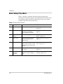
XTR 1700 Watt AC Input Wire Connection
To make the AC input wire connections:
1. Strip the outside insulation on the AC cable approximately 4 in.
(100 mm). Trim the wires so that the ground wire is 0.5 in. (12 mm)
longer than the other wires. Strip 0.55 in.(14 mm) at the end of each
of the wires.
2. Loosen the screw on the AC cover and remove the AC cover.
3. Unscrew the base of the strain relief from the helix-shaped body.
Insert the base through the outside opening in the AC input cover and,
from the inside, screw the locknut securely onto the base.
4. Slide the helix-shaped body onto the AC cable. Insert the stripped
wires through the strain relief base until the outer cable jacket is flush
with the edge of the base. Tighten the body to the base while holding
the cable in place. The cable is now securely fastened inside the strain
relief.
5. Route the AC wires to the input connector terminals as required. For
AC input terminal locations, see lower inset in Figure 2-1. To connect
the wiring, loosen the terminal screw, insert the stripped wire into the
terminal, and tighten the screw securely.
975-0200-01-01
2-7
2
Installation
6. Route the wires inside the cover to prevent pinching. Fasten the AC
cover to the unit using the screw provided. See Figure 2-1.
2-8
975-0200-01-01
Step 4: Selecting Load Wires
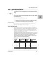
Step 4: Selecting Load Wires
This section provides recommendations for selecting minimum load wire
sizes.
Load Wiring
To select the wiring for connecting the load to the power supply, consider
the following factors:
•
•
•
•
Insulation rating of the wire.
Current carrying capacity of the wire.
Maximum load wiring length for operation with remote sense lines.
Electrical noise and impedance effects of the load lines.
Insulation Rating
Use load wiring with a minimum insulation rating equivalent to the
maximum output voltage of the power supply.
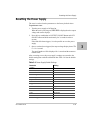
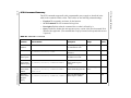
Current Carrying Capacity
The load wiring must have a current carrying capacity greater than the
output rating of the power supply to ensure that the load wiring will not be
damaged if the load is shorted. Table 2-3 shows the maximum current
rating for various gauges of wire rated for 105 °C operation, based on a
maximum current density of 450 A/cm2.
Operating at the maximum current rating shown in Table 2-3 results in an
approximately 30 °C temperature rise for an appropriately-sized load wire
operating in free air. Where load wiring must operate in areas with
elevated ambient temperatures or bundles with other wiring, use larger
gauges or wiring rated for higher temperatures.
Table 2-3 Current Carrying Capacity for Load Wiring
975-0200-01-01
Wire Size
(AWG)
Maximum Current
(Amps)
Wire Size
(AWG)
Maximum Current
(Amps)
20
2.5
6
61
18
4
4
97
16
6
2
155
14
10
1
192
12
16
1/0
247
10
21
2/0
303
8
36
2-9
2
Installation
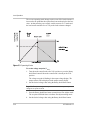
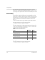
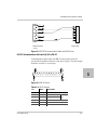
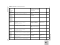
Maximum Load Wiring Length For Operation With Sense Lines
Figure 2-2 Maximum Load Wire Length for 1 V Line Drop
Noise and Impedance Effects
To minimize noise pickup or radiation, use shielded twisted pair wiring of
the shortest possible length for load sense wires. Connect the shield to the
power supply chassis. Where shielding is impossible or impractical,
simply twisting the wires together will offer some noise immunity.
2-10
975-0200-01-01
Step 5: Performing Functional Tests
Step 5: Performing Functional Tests
The functional test procedures include:
•
•
Power-on and front panel functional checks
Voltage mode operation and current mode operation checks.
For information on local operation, see “Local Operation” on page 3–1
for adjusting front panel controls and settings.
2
Powering the Power Supply On/Off
To power on the power supply:
1. Ensure that the front panel power switch is in the Off position.
2. Ensure that the AC line voltage is within operating range.
3. Connect the line cord to a grounded AC outlet.
4. Turn the front panel power switch to the On position.
After a short power-on delay, 8888 8888 illuminates on the output
voltage and current displays, followed by PSU On.
After approximately 1 second, the display returns to normal status.
To power off the power supply:
u Turn the front panel power switch to the Off position.
AC FAIL will blink on the display. The ALARM LED illuminates.
After a short delay, all lights on the display will not be illuminated.
975-0200-01-01
2-11
Installation
Voltage and Current Mode Operation Checks
To perform the voltage and current mode operation checks:
1. Ensure that the front panel power switch is in the On position and the
output is disconnected.
2. If the OUTPUT ON/OFF button is illuminated, press the button to
turn off the output.
3. To check voltage mode operation, turn the mode control knob to the
VOL position.
The voltage set point will blink dimming and then return to full
brightness. For more information, see “Local Operation” on page 3–1.
4. Adjust the voltage to 5 V.
5. To check current mode operation, turn the mode control knob to CUR
position.
Verify that the current set point is blinking in the output current
display.
6. Adjust the current to 1 A.
7. Press the OUTPUT ON/OFF button to turn On.
8. Turn the front panel power switch to the Off position.
9. Turn the front panel power switch to the On position.
10. Connect a short circuit across the output terminals. Use leads of
sufficient current carrying capacity. (See “Step 4: Selecting Load
Wires”.)
11. If the OUTPUT ON/OFF button is not illuminated, press the button to
turn on the output.
CC Mode LED illuminates and the voltage and current are displayed.
CV Mode LED illuminates and the preset load current is displayed.
12. Turn the front panel power switch to the Off position.
2-12
975-0200-01-01
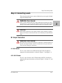
Step 6: Connecting Loads
Step 6: Connecting Loads
This section describes how to connect loads to the power supply for both
single and multiple loads.
WARNING: Shock hazard
There is a shock hazard at the power supply output when operating at an output
greater than 40 V. To protect personnel against accidental contact with hazardous
voltages, ensure that the load and its connections have no accessible live parts.
CAUTION
When making connections to the output terminals, ensure terminals of opposite
polarity do not touch. Load cables and sense wires should be provided with strain
relief.
DC Output Connectors
WARNING: Shock hazard
Disconnect the AC input before making any connections. A shock hazard may be
present at the output terminals. Allow 15 seconds after the AC power has been
removed before making any connections.
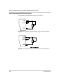
6 V–40 V Models
The 6 V–40 V models of the XTR 850 Watt and XTR 1700 Watt are
equipped with output terminals, as shown in Figure 1-3 and Figure 1-6.
60 V–600 V Models
The 60 V–600 V models of the XTR 850 Watt and XTR 1700 Watt are
equipped with output connectors, as shown in Figure 1-4, Figure 1-5, and
Figure 1-7.
975-0200-01-01
2-13
2
Installation
Inductive Loads
To prevent damage to the power supply from inductive kickback, connect
a diode across the output. The diode must have a voltage rating at least
20% greater than the power supply's output voltage and have a current
rating greater than or equal to the power supply's output rating. Connect
the cathode to the positive output and the anode to the return.
Where positive load transients such as back EMF from a motor may
occur, connect a Transient Voltage Suppressor (TVS) or a varistor across
the output to protect the power supply. The breakdown voltage rating for
the TVS or varistor must be approximately 10% higher than the rated
supply output.
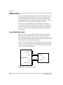
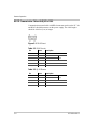
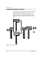
Connecting Single Loads
Figure 2-3 shows the recommended load connections for a single load
which is sensing its voltage locally. Local sense lines shown are the
default connections at the rear panel APG J1 connector (see Figure 4-1 on
page 4–5). The load lines should use the largest gauge and shortest length
of wire possible to ensure optimal performance.
You do not need remote sensing for basic operation of your power supply.
However, if you wish to correct any small drops in your load lines, then
use the remote sensing feature. See “Step 7: Connecting Remote Sensing”
on page 2–16 for more information.
– Local Sense
J1.1
J1.2
+ Output
Power Supply
Load
– Output
+ Local Sense
+ Terminal
–Terminal
J1.5
J1.6
Figure 2-3 Connecting Single Loads
2-14
975-0200-01-01
Step 6: Connecting Loads
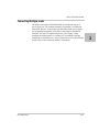
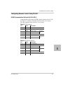
Connecting Multiple Loads
The proper connection of distributed loads is an important aspect of
power supply use. The common method of connection is a radial load
connection. Power is connected to each load individually from a single
pair of terminals designated as the positive and negative distribution
terminals. This pair of terminals may be the power supply output
terminals, the load terminals, or a distinct set of terminals especially
established for distribution use. In this scheme, there are no ground loops
and the effect of one load upon another is minimized.
975-0200-01-01
2-15
2
Installation
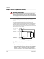
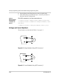
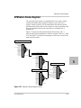
Step 7: Connecting Remote Sensing
WARNING: Shock hazard
There is a potential shock hazard at the sense connectors when using a power
supply at an output greater than 40 V. Select wiring with a minimum insulation
rating equivalent to the maximum output voltage of the power supply for use as
local sense jumpers or for remote sense wires. Ensure that connections at the load
end are shielded to prevent contact with hazardous voltages.
Remote sensing permits you to shift the regulation point of the power
supply from the output terminals to the load or other distribution
terminals.
Use shielded twisted pair wiring of 20 to 26 AWG for best noise
performance. Make sure that the shielded twisted pair wiring insulation is
rated higher than the maximum output voltage of the power supply. If
possible, one end of the shield of the sense lines should be attached to the
chassis ground of the power supply.
Pin J1.6 on APG
connector
-SNS
Pin J1.1 on APG
connector
+SNS
LOAD
output +
Output terminals on
power supply
output Chassis ground stud
Figure 2-4 Remote Sense Connection
To connect the remote sense wires:
1. Ensure that the front panel power switch is in the Off position.
2. Using a small flat blade screwdriver, remove the two sense jumpers
from pins J1.1 and J1.2, and from pins J1.5 and J1.6 on the APG
Connector. See Figure 4-1, “APG Connector Terminals” on page 4–5.
2-16
975-0200-01-01
Step 7: Connecting Remote Sensing
3. Connect one end of the shielded twisted pair wire to the chassis
ground point on the power supply.
4. Connect the positive sense line (+SNS) from the positive regulation
point as close as possible to the load terminals to pin J1.1.
5. Connect the negative sense line (–SNS) from the return of the load to
pin J1.1.
To compensate for losses in power leads connected to the output, the
power supply provides sense connections beside the output terminals.
With remote sense leads in place, the power supply regulates to the
displayed voltage at the point where the sense lines are connected to
the output leads. With the sense lines disconnected, the power supply
regulates the voltage at the output terminals.
CAUTION
Do not operate the power supply with sense lines connected to the load without
also connecting the load power leads to the output terminals.
CAUTION
Avoid reversing positive (+) and negative (–) sense connections.
When using remote sense to compensate for load line losses, ensure that the
positive sense line is connected to the positive load terminal and the negative
sense line is connected to the negative load terminal. Do not reverse these
connections or the power supply may be damaged.
Important: Long load leads with large capacitance at the load and remote
sensing can cause voltage instability due to inductance of the load leads.
Measures to reduce inductance and/or capacitance (raising resonant frequency)
or using local sense can be beneficial in stabilizing the system.
975-0200-01-01
2-17
2
2-18
3
Local Operation
Chapter 3, Local Operation, provides the procedures for
local (front panel) operation such as:
• Configuring settings.
• Operating in constant voltage mode and constant
current mode.
• Using the protection features.
• Using multiple power supplies.
Local Operation
Introduction
Once you have installed the power supply and connected both the AC
input power and the load (covered in “Installation” on page 2–1), the
power supply is ready for local operation. To turn the power supply on,
see “Powering the Power Supply On/Off” on page 2–11.
Configuring Settings from the Front Panel
Using the 9-Position Mode Control Knob
The 9-position mode control knob is used with the Rotary knob/Enter
button to configure settings in local operation. See Figure 1-2, “Front
Panel Display and Controls” on page 1–5 for location of the front panel
features.
The mode control knob is used to select one of nine modes: VOL, CUR,
FLD, PRT, SAV, RCL, CAP, and VAP. See Figure 3-1 and Table 3-1 for
detailed information on the nine modes.
Figure 3-1 9 Position Mode Control Knob
Using the Rotary knob/Enter button
The Rotary knob/Enter button is used to change settings and set the value
selected. The front panel displays information on the output voltage and
output current displays. Each display has a maximum of four characters
that are made up of 7 segments.
Coarse and Fine Adjustment Modes
Coarse
adjustment
mode
3-2
When using local operation to set the current and voltage set points, enter
the coarse adjustment mode followed by the fine adjustment mode. The
coarse adjustment mode quickly adjusts the settings in large increments to
reach the desired value.
975-0200-01-01
Configuring Settings from the Front Panel
Fine adjustment
mode
Pressing the Rotary knob/Enter button to change the mode to fine
adjustment mode provides the ability to manipulate the last significant
digit. Once the exact desired value for the setting has been selected, press
the Rotary knob/Enter button to commit the value to the unit. The coarse
and fine adjustment modes are used for setting the voltage and current set
points, OVP and UVP settings.
Table 3-1 Select and Set from the Front Panel
9 Positions on the Mode
Control Knob
Pressing the Enter Button lets
Turning the Rotary Knob lets you… you…
VOL (Voltage Programming)
Select the voltage set point in coarse
or fine adjustment modes. See
“Automatic Mode Crossover” on
page 3–11.
CUR (Current Programming)
Select the current set point in coarse Set the value selected and
or fine adjustment modes. See
cycle to the next setting.
“Constant Current Mode Operation”
on page 3–11.
FLD (Foldback)
Select Foldback option: CC, CV or
none. See “Setting Foldback Mode”
on page 3–22.
Set the value selected and
cycle to the next setting.
PRT (Protection)
Select the OVP set point (see
page 3–24).
Select the UVP set point (see
page 3–25.)
Select OTP temperature and
Shutdown (see page 3–26.)
Set the value selected and
cycle to the next setting.
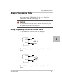
SAV (Save User Preset)
Select the user setting memory
location. See “Saving User Setting
Memory Locations” on page 3–28.
Save user setting memory
values.
RCL (Recall User Preset)
Select the user setting memory
location. See “Recalling User
Setting Memory Locations” on
page 3–29.
Load user setting memory
values into the power supply.
CAP (Current Analog
Programming)
Select the programming source and
select the range.
Set the value selected and
cycle to the next setting.
VAP (Voltage Analog
Programming)
Select the programming source and
select the range.
Set the value selected and
cycle to the next setting.
975-0200-01-01
Set the value selected and
cycle to the next setting.
3
3-3
Local Operation
Navigating the Menu System
The menu system of the XTR follows a select and set model with the
exception of the VOL and CUR modes. See “Setting VOL and CUR
Modes”.
The general procedure for setting up the features in the select and set
model is:
1. To select a mode, rotate the 9-position mode control knob to the
desired mode or press the Rotary knob/Enter button once to activate
the current selection on the mode control knob. See Figure 3-2.
2. To select the feature or setting, rotate the Rotary knob/Enter button to
scroll through the different available settings of that mode.
The settings appear on the output current display.
3. Press the rotary knob/Enter button to select the feature or setting.
4. Set each value using the Rotary knob/Enter button. When the value
has been selected, press the Rotary knob/Enter button to commit the
updated value. Additional values may become available, depending
on the setting that is being configured.
Setting VOL and CUR Modes
The only exceptions to the select and set model are the VOL and CUR
modes which do not allow the selection of tracking and select and set
mode by rotating the Rotary knob/Enter button. In VOL and CUR modes,
the default entry mode setting is automatically selected as either voltage
or current tracking, respectively.
Voltage and current values can be set in tracking mode or select and set
mode using the Rotary knob/Enter button:
•
Tracking mode—the new values take effect as the Rotary knob/Enter
button is rotated.
• Select and set mode—the new values do not take effect until the
Rotary knob/Enter button is pressed. See “Normal Display Mode and
Inactivity Timeout” on page 3–6.
To access the tracking mode for entering voltage and current:
1. Select the VOL or CUR position on the mode control knob.
•
3-4
If the set point is blinking, the unit is in coarse tracking mode.
When the VOL mode is selected, the voltage set point will blink in
the output voltage display.
975-0200-01-01
Navigating the Menu System
•
When the CUR mode is selected, the current set point will blink in the
output current display.
2. Use the Rotary knob/Enter button to adjust the set point.
The adjustments you make to the set point affect the opposing output
value (voltage when in CUR mode or current when in VOL), which
will update in the non-blinking display.
3. Press the Rotary knob/Enter button to enter fine adjust tracking mode.
The set point blinks faster when the unit is in fine adjust tracking
mode.
4. Use the Rotary knob/Enter Button to fine tune the set point.
5. Once the set point has been selected, press the Rotary knob/Enter
Button to exit tracking mode and return to normal display mode.
To access the select and set entry mode for the voltage and current set
points:
1. Select VOL or CUR position on the mode control knob.
2. Press the Rotary knob/Enter button twice to scroll past the coarse and
fine tracking modes without making any adjustment to the value.
Coarse select and set mode has been selected.
3. If a change is made accidentally in tracking mode, select and set
mode will not be available and you’ll need to start again at Step 1.
4. Select the desired value for this set point and then set the value using
the Rotary knob/Enter button.
975-0200-01-01
3-5
3
Local Operation
Normal Display Mode and Inactivity Timeout
Normal display mode appears on the output voltage and current displays
when the configuration changes from the front panel have been completed
or when the inactivity timeout occurs (default is 3 seconds). Normal
display mode shows the output voltage and current values.
If a timeout occurs before the changes made to the value have been set,
the changes will not be saved and you will have re-enter the changes. The
inactivity timeout is variable from 1 to 20 seconds and can only be
changed using the SCPI command.
The SCPI command (s) for these instructions are:
[:]SYSTem[<channel>]:FPANel[:TIMeout]
Important: Each user memory setting location stores the timeout so that
beginning users and expert users don't have to use the same timeout
3-6
975-0200-01-01
Navigating the Menu System
VOL
Coarse Volt Tracking
Fine VoltTracking
Coarse Volt Pre-Set
Fine VoltPre-Set
CUR
Coarse Current Tracking
Fine Current Tracking
Coarse Current Pre-Set
Fine Current Pre-Set
FLD
CV
Fold Delay
CC
Fold Delay
None
PRT
OVP
OVP Coarse Adjust
OVP Fine Adjust
UVP
UVP Coarse Adjust
UVP Fine Adjust
OverheatProtection
On/Off
Shutdown Logic
1/0
SAV
Select Preset
RCL
Select Preset
CAP
Off
VAP
3
Legend:
Press Rotary Knob/Enter Button
when no modification of the
tracking value hasbeen made.
Voltage Isolated
Current APG Level
Voltage Non-Isolated
Current APG Level
Resistive Isolated
Current APG Level
Resistive Non-Isolated
Current APG Level
Press Rotary Knob/Enter Button
Rotate RotaryKnob/Enter
Button
Off
Voltage Isolated
Voltage APGLevel
Voltage Non-Isolated
Voltage APGLevel
Mode Knob State
PGM
Resistive Isolated
Voltage APGLevel
Resistive Non-Isolated
Voltage APGLevel
USB
Address (1-30)
Setting/Value
LAN
Address (1-30)
GPIB
Address (1-30)
RS-232
Data Rate
Address (1-30)
RS-485
Data Rate
Address (1-30)
Slave
Address (1-30)
Local Lock
On/Off
Figure 3-2 Front Panel Menu System
975-0200-01-01
3-7
Local Operation
Display Messages on the Front Panel
The front panel displays on the power supply will use text as shown in
Table 3-2 to indicate the status or mode.
Table 3-2 Front Panel Display Text
3-8
Display Text
Text Description
0
232
485
8888
|
AC
ADDr
ANPR
AS
AvAS
BP5
CAPr
CLr
CC
CU
CrPC
CrPU
CUrr
deLa
done
Err
F0LD
FAIL
FAn
FLA
FnpC
FnPU
FLd
GPIB
In
LAn
LE C
Negative Polarity
RS 232
RS 485
All segments On, Power Up
Positive Polarity
Alternating Current
RS 485 Address
Analog Programming
Power On Autostart
Auxiliary Autostart
Data rate (BPS)
Current Analog Programming
Clear
Constant Current
Constant Voltage
Coarse Current Pre-set Mode
Coarse Voltage Pre-set Mode
Current
Fold Delay
Done
Error (debug)
Foldback
Fail
Fan
Flash
Fine Current Preset Mode
Fine Voltage Preset Mode
Foldback
GPIB Interface
Interlock
ENET Interface
Current APG Level
975-0200-01-01
Display Messages on the Front Panel
Table 3-2 Front Panel Display Text
Display Text
Text Description
LE U
Loc
LOCL
OFF
OCP
O7P
OUP
OvPF
On
OUPC
POL
Pr0
PSU
R IS
rCL
rE
rnIS
SAFE
SAUE
Sd
SLA
U IS
UN IS
USb
UUP
UvPF
UAPr
UOL
Voltage APG Level
Lock
Local
Off
Over Current Protection
Over Temperature Protection
Over Voltage Protection
Over Voltage Protection fine adjustment
On
OVP Calibration
Polarity
Protection mode
Power Supply Unit
Isolated Resistive Analog Programming
Recall Preset
Remote Programming/Interface
Non-Isolated Resistive Analog Programming
Safe
Save Preset
Shutdown
Slave Remote Interface
Isolated Analog Voltage Programming
Non-Isolated Analog Voltage Programming
USB Interface
Under Voltage protection coarse adjustment
Under Voltage protection fine adjustment
Voltage Analog Programming
Voltage
3
A blinking numeric value is either a voltage or current set point in tracking
mode. The display in which the set point appears, output voltage or output
current display, indicates the type of set point, voltage or current.
975-0200-01-01
3-9
Local Operation
Standard Operation
The power supply can be controlled by two methods, either from the front
panel or from any of the remote interfaces. Front panel control is referred
to as local operation (default setting) while control via any of the remote
interfaces is called remote operation. To set up the power supply for
remote operation, see Chapter 5, “Remote Operation”. Once the remote
connection has been established, the power supply can switch seamlessly
between local operation and any digital interface (RS-232, RS-485,
GPIB, USB and Ethernet).
Local lockout is a feature that allows the front panel to be locked so that
accidental button presses are ignored. This feature is often used to lock
out the front panel while a user is controlling the power supply from a
remote location.
The output of the power supply has two modes of operation: Constant
Voltage (CV) mode (see page 3–11) and Constant Current (CC) mode
(see page 3–11). Both of the operating modes are available regardless of
which control method (local or remote) is used.
Operating Modes
The output mode in which the power supply operates at any given time
depends on the following factors:
•
Output voltage set point VSET
•
Output current set point ISET
•
Impedance of the attached load RL
The two output modes of operation are Constant Voltage (CV) mode (see
page 3–11) and Constant Current (CC) mode (see page 3–11).
Output enabled
3-10
When the output is turned on, both the voltage and current rise as quickly
as possible to try and reach the set points (VSET and ISET) that were
configured prior to enabling the output. Initially the unit will operate in
CV mode, which is the default mode. As the voltage and current rise to
meet the requirements of the load, the set point that is reached first (based
on the RL, either VSET and ISET) will determine which mode the power
supply will remain in. The operating mode is indicated by either the CC
mode LED or the CV mode LED, one of which will illuminate on the
front panel.
975-0200-01-01
Standard Operation
Output disabled
The mode of operation is not determined until the output is enabled. The
CV and CC mode LEDs will not indicate the mode while the output is
disabled.
Constant Voltage Mode Operation
If the output is enabled and the configured current set point is much
higher than the requirements for the attached load, then the voltage will
rise until it reaches the voltage set point. When the output voltage reaches
the voltage set point, it stops rising. The unit will continue to operate in
CV mode. The load current will still vary to meet any changes in required
load current draw resulting from a change in the attached load.
Constant Current Mode Operation
If the output is enabled, the voltage and current start to rise. At this time
the unit is operating in CV mode (default operational mode). As the load
current drawn reaches the value of the output current setting, the unit will
switch to CC mode and not allow any additional current to be drawn
above the value of ISET. The unit is now operating in CC mode. The
voltage will still vary to meet any changes in required output voltage
resulting from a change in the attached load.
Automatic Mode Crossover
Mode crossover occurs when the unit makes the switch between operating
modes. Crossover can occur from CV to CC or vice versa, depending on
how the attached load resistance changes. Figure 3-3 shows the
relationships between the variables.
For example, if the unit was initially operating in CV mode with the
output voltage at the voltage set point and the load current below the ISET
and the attached load resistance began to decrease, the current would rise
to meet this change in the load. The load current will increase in
proportion to the decrease in the load resistance until the load current
drawn reaches the current set point. At this point further decreases in load
resistance (increased load current requirements) will cause the unit to
cross over into CC mode where the output voltage will vary with
changing load resistance and the load current will remain at the ISET
value.
975-0200-01-01
3-11
3
Local Operation
The reverse operating mode change can also occur if the load resistance is
increased to the point that the required load current drops below the ISET
value. At that point the power supply would crossover to CV mode and
the load current would be free to vary as the load resistance changed
Figure 3-3 Operating Modes
To set the voltage set point (VSET):
1. Turn the mode control knob to the VOL position or press the Rotary
knob/Enter button if the mode control knob is already at the VOL
position.
The voltage set point is blinking in the output voltage display. The
output current will be displayed in the output current display.
2. Set the desired voltage value using the Rotary knob/Enter button.
Important: If you can’t get the set point to the desired level, you may need to
change the set points for OVP.
3. Press the Rotary knob/Enter button to transition to Fine Adjust mode.
The set point will blink faster to indicate fine adjust tracking mode.
4. Set the desired voltage value using the Rotary knob/Enter button.
3-12
975-0200-01-01
Standard Operation
5. Once the desired value has been set, press the Rotary knob/Enter
button to commit the setting.
Important: The control circuits have been designed to allow you to set the
output voltage up to 105% over the model-rated maximum value. The power
supply will operate within these extended ranges, but full performance to
specification is not guaranteed.
Quick Tip
Remote operation
uses these SCPI
commands. See
page 5–1.
The SCPI command (s) for these instructions are:
[[:]SOURce[<channel>]]:VOLTage[:LEVEl][:IMMediate]
[:AMPLitude]
Important: The maximum and minimum setting values of the output voltage
are limited by the Over Voltage Protection and Under Voltage Protection settings.
To set the current set point (ISET):
1. Turn the mode control knob to the CUR position or press the Rotary
knob/Enter button if the mode control knob is already at the CUR
position.
The voltage set point is blinking in the output voltage display. The
output current will be displayed in the output current display.
2. Set the desired current value using the Rotary knob/Enter button.
3. Press the Rotary knob/Enter button to transition to Fine Adjust mode.
The set point blinks faster to indicate fine adjust tracking mode.
4. Set the desired current value using the Rotary knob/Enter button.
5. Once the desired value has been set, press the Rotary knob/Enter
button to commit the setting.
Important: The control circuits have been designed so that output
current can be set up to 105% over the model-rated maximum values. The power
supply will operate within these extended ranges, but full performance to
specification is not guaranteed.
The SCPI command (s) for these instructions are:
[[:]SOURce[<channel>]]:CURRent[:LEVEl][:IMMediate]
[:AMPLitude]
975-0200-01-01
3-13
3
Local Operation
Shipped Configuration (Local Operation)
The power supply is configured for local operation at the factory. See
Table 3-3 for a summary of this configuration. For more information on
default settings, see Table 3-9 on page 3–35.
Table 3-3 Shipped Configuration
Local Control Configuration
Additional References
Use the front panel controls to
adjust the output voltage and
current set point settings.
See Chapter 3, “Local Operation” for front
panel operation. See Chapter 4, “Analog
Programming (APG) and Isolated Analog
Programming (ISOL)” for analog
programming procedures.
The OVP set point is adjusted at
the front panel to 105% above the
maximum rated output voltage.
See “Using Over Voltage Protection
(OVP)” on page 3–24 for the adjustment
procedure.
Turning the Output On/Off
Turning the output on will also turn off the ALARM LED if the ALARM
LED has been latched on due to an alarm triggering and automatically
clearing. See “Alarms and Errors” on page 3–17.
To turn on the output power:
u Press the OUTPUT ON/OFF button on the front panel or enter the
SCPI command.
The OUTPUT ON/OFF button will illuminate.
To turn off the output power:
u Press the OUTPUT ON/OFF button when the OUTPUT ON/OFF
button is illuminated.
The output will turn off and the LEDs will not be illuminated.
Important: The main output will not turn on if the shutdown function is
activated. See “Using the External Shutdown Function” on page 3–31.
Quick Tip Remote
Operation uses
these commands.
See page 5–1.
3-14
The SCPI command (s) for these instructions are:
[:]OUTPut[<channel>][:POWer][:STATe]
975-0200-01-01
Turning the Auxiliary Output On/Off
Turning the Auxiliary Output On/Off
To turn on the auxiliary output:
u Press the AUX ON/OFF button on the front panel.
The AUX ON/OFF button will illuminate.
Important: The auxiliary output will not turn on if Pin J3.1 (AUX_ON_OFF)
and Pin J3.2 (or Pin J3. 6 COM_ISOLATED) are shorted.
See “AUX Output and Isolated Analog Programming (ISOL) Connector” on
page 4–19.
To turn off auxiliary output:
u Press the AUX ON/OFF button on the front panel again.
The AUX ON/OFF button will not be illuminated.
If the auxiliary output is activated, +5 V on J3.9 (+AUX1) and +15 V on
J3.11 (AUX2) will be present with respect to Pin J3.2 or Pin J3.6
(COM_ISOLATED). (See also “AUX Output and Isolated Analog
Programming (ISOL) Connector” on page 4–19 for more details.)
The SCPI command (s) for these instructions are:
[:]OUTPut[<channel>]:AUXiliary[:STATe]
Output Auto Start Mode (Auto Restart)
The Auto Start mode establishes the state of the output of the power
supply after recovery from a complete power cycle (all front panel LEDs
are not illuminated).
If Auto Start mode is set to On, the power supply output will return to its
previous value when the power supply is powered up again.
If Auto Start mode is set to Off, the power supply output will remain off
after the power supply is powered up again.
To change the Auto Start mode:
1. Press and hold the OUTPUT ON/OFF button for 1 second.
AS On or AS Off is displayed.
2. Switch the Auto Start mode.
The SCPI command (s) for these instructions are:
[:]OUTPut[<channel>][:POWer][:STATe]:PowerON[:STATe]
975-0200-01-01
3-15
3
Local Operation
Auxiliary Auto Start Mode
The Auxiliary Auto Start mode determines the state of the auxiliary
output after a complete power cycle (all front panel LEDS are not
illuminated). With Auxiliary Auto Start mode turned to On, the auxiliary
output will be activated after the power supply is powered up again.
To define the Auxiliary Auto Start mode:
1. Press and hold the AUX ON/OFF button for 1 second.
AuAS On or AuAS Off is displayed.
2. To change to status to On or Off, press the AUX ON/OFF button.
The SCPI command (s) for these instructions are:
[:]OUTPut[<channel>]:AUXiliary:PowerON[:STATe]
3-16
975-0200-01-01
Alarms and Errors
Alarms and Errors
Several conditions can cause alarms in the XTR. Some conditions are:
•
•
From user configurable features.
Controlled in hardware and will trigger regardless of configuration.
All alarms, with the exception of the Fan alarm, will result in the output of
the power supply being disabled. The Fan alarm does not affect the output.
When an alarm is triggered, the appropriate alarm message will begin
blinking on the display and the Alarm LED will be illuminated.It is
possible that more than one alarm will trigger at the same time. When this
occurs, the alarm with the highest precedence will blink on the display.
Table 3-4 lists the precedence of alarms. If the alarm is cleared and the
event which caused the alarm has not been corrected, then the alarm may
trigger again immediately. Fix the reason for the alarm before you clear it.
Table 3-4 Alarm Order of Precedence
Alarm
Precedence
Output
Latch
Maskable
Display
AC Fail
1 (Highest)
Yes
No
AC Fail
Over Temperature Protection (OTP
2
Yes
Yes
O7P Pro
Over Temperature Protection (OTP) Slave
(1700 W version only)
3
Yes
Yes
O7P Pro
Fan
4
No
Yes
FAn Pro
Fan Slave (1700 W version only)
5
No
Yes
FAn Pro
Interlock
6
No
No
In Loc
Over Voltage Protection
7
No
No
OVP Pro
Over Current Protection
8
No
No
OCP pro
Foldback
9
Yes
Yes
FLD Pro
External Shutdown
10 (Lowest)
No
Yes
SD POL
Flash Checksum Failure1
N/A
N/A
N/A
FLA FAIL
1.The Flash Checksum Failure alarms are an exception as they are a terminal alarm that can only
occur during boot up. It can only be cleared by doing a soft reset (losing the configuration of the
unit) or by power cycling the unit.
975-0200-01-01
3-17
3
Local Operation
Clearing Alarms
Clearing Triggered and Manual Alarms
To clear a triggered alarm, use one of the following methods:
• Turn the power supply Off and then On.
• Press and hold the Rotary knob/Enter button for 3 seconds.
• Press the reset key combination (Flash Fail ONLY). See “Resetting the
Power Supply” on page 3–35.
To clear a manual alarm:
1. Press the Rotary knob/Enter button for 3 seconds.
The Alr Clr message will be displayed on the front panel for a few
seconds.
Important: When an alarm is cleared by using this method, only the current
highest precedence alarm is cleared. If another alarm has occurred, then this
alarm will not become the highest precedence alarm and will begin blinking on
the display.
2. Repeat the alarm clearing until you have cleared all alarms.
Clearing a Flash Failure Alarm
The Flash Failure alarm is the only exception for clearing alarms. Flash
failure can only be cleared by a reset (see “Resetting the Power Supply”
on page 3–35) or by power cycling the unit.
To clear a triggered alarm, use one of the following methods:
• Turn the power supply Off and then On.
• Press and hold the Rotary knob/Enter button for 3 seconds.
• Press the reset key combination (Flash Fail ONLY). See “Resetting
the Power Supply” on page 3–35.
The SCPI command (s) for these instructions are:
[:]OUTPut[<channel>]:PROTection:CLEar
3-18
975-0200-01-01
Alarms and Errors
Clearing Automatic Alarms
Some alarms will clear automatically when the condition that caused the
alarm is no longer present. When an alarm automatically clears, the
output voltage and current displays will return to normal, but the ALARM
LED will remain illuminated to indicate that an alarm has occurred. If an
automatic alarm is triggered, the normal alarm clearing procedure still
applies.
To clear the ALARM LED after an automatic alarm has cleared, use
one of the following methods:
• Send the SCPI Clear Alarm command.
• Press the OUTPUT ON/OFF button to reenable the output.
The ALARM LED will no longer be illuminated.
For example, if one of the fans in the XTR was temporarily blocked,
causing a Fan alarm, then the blockage was cleared and the fans restarted,
the alarm would clear. The output voltage and current displays would be
in normal mode, but the ALARM LED would be illuminated. See “Front
Panel ALARM LED” on page 3–19 for information on other events that
affect the ALARM LED.
Alarms status is tracked in the SCPI status registers. For more details on
how and where the alarms are tracked, see “Standard SCPI Register
Structure” on page 5–32.
Front Panel ALARM LED
The Alarm LED will illuminate due to one or more of the following
events occurring:
•
•
•
•
•
•
•
•
•
•
975-0200-01-01
OTP has been tripped.
A fan has stopped.
OVP has tripped.
OCP has tripped.
Interlock is open circuit.
AC power falls out of range.
Foldback has tripped.
Persistent storage checksum is wrong (Flash Fail alarm).
Internal malfunction of power supply.
Any alarm has tripped and been cleared automatically.
3-19
3
Local Operation
The alarm LED will remain illuminated until the alarm is manually
cleared (see “Clearing Triggered and Manual Alarms” on page 3–18) or
by turning the main output on if the alarm has automatically been cleared.
Alarm Masking
It is possible to completely disable some alarms through the use of the
alarm mask. If an alarm is masked then this masking will prevent it from
registering in the SCPI conditions registers as well as not triggering the
alarm. The alarms that can be masked are identified in Table 3-4 on
page 3–17.
Control of the alarm mask is only available using the SCPI command.
The SCPI command (s) for these instructions are:
[:]SYSTem[<channel>]:PROTection:MASK
The mask command takes a single parameter made up of the sum of the
values for the alarms that are to be masked. See Table 3-5 for the alarm
values associated with each maskable alarm.
Table 3-5 Alarm Mask Bit Positions
Alarm
Bit Position
Value
Over Temperature Protection (OTP)
2
2
Over Temperature Protection (OTP) Slave
(1700W version only)
3
4
Fan
4
8
Fan Slave
(1700W version only)
5
16
Foldback
8
128
External Shutdown
9
256
The SCPI command (s) for these instructions are:
[:]SYSTem[<channel>]:PROTection:MASK
3-20
975-0200-01-01
Alarms and Errors
Alarm Output Latching
When an alarm is triggered, the output will be disabled with the exception
of the Fan alarm. When an alarm is cleared, the alarm output latch
determines if the output should be re-enabled to the state before the alarm
occurred or if the output should remain in the off state.
The output latches are accessible through the SCPI command.
The SCPI command (s) for these instructions are:
[:]SYSTem[<channel>]:PROTection:LATCh
The latch command take a single decimal parameter made up of the sum
of the values for the alarms to determine if they are to be latched in the off
state on clearing. See Table 3-6 for the values associated with each
latchable alarm.
Table 3-6 Alarm Latch Bit Positions
975-0200-01-01
Alarm
Bit
Position
Value
AC Fail
1
1
Over Temperature Protection (OTP)
2
2
Over Temperature Protection (OTP) Slave
(1700 W version only)
3
4
Foldback
8
128
3-21
3
Local Operation
Setting Foldback Mode
Foldback mode is used to disable the output when a transition is made
between the operating modes. The power supply will turn off/disable the
output and lock in foldback mode after a specified delay if the power
supply transitions into CV mode or into CC mode, depending on the
foldback mode settings. This feature is particularly useful for protecting
current or voltage sensitive loads. Foldback can be set to trigger a switch
when transitioning from CV to CC mode or from CC to CV mode.
To set the foldback protection and foldback delay time:
1. Turn the mode control knob to the FLD position or press the Rotary
knob/Enter button if the mode control knob is already at the FLD
position.
2. Select the type of crossover that will cause foldback to trigger by
using the Rotary knob/Enter button.
If the mode selected is CC or CV mode, the foldback delay timer will
start on a transition into the selected mode. If the mode selected is
none, foldback is not enabled.
3. Press the Rotary knob/Enter button when the desired mode has been
selected.
The FLD LED will illuminate and DELA will be displayed in the
output voltage display.
4. Adjust the desired delay time using the Rotary knob/Enter button.
The range can be set from 0.50 seconds to a maximum of 50 seconds.
The step size is in increments of 0.05 seconds when setting from 0.50
to 5 seconds and then in 1 second increments from 5 seconds to 50
seconds.
5. Once the desired foldback delay time has been selected, press the
Rotary knob/Enter button to commit the foldback delay setting.
To disable foldback protection:
1. Turn the mode control knob to the FLD position or press the Rotary
knob/Enter button if the control knob is already at the FLD position.
2. FLd is displayed on the output voltage display and the output current
display shows the current foldback trigger mode.
3. Turn the Rotary knob/Enter button until nonE is displayed in the
output current display.
3-22
975-0200-01-01
Setting Foldback Mode
4. Press the Rotary knob/Enter button to commit the setting once the
desired value has been set.
5. The green FLD LED will turn off and the display will return to the
normal display mode.
The SCPI command (s) for these instructions are:
[:]OUTPut[<channel>]:PROTection:FOLDback[:MODE]
[:]OUTPut[<channel>]:PROTection:FOLDback:LATCh
Important: If you set foldback while the output is enabled and the trigger you
select is the same as the current operating mode, the foldback timer will begin
counting immediately after the delay time has been set.
3
Resetting Activated Foldback Protection
To reset activated and latched foldback protection, press and hold the
Rotary knob/Enter button for approximately 3 seconds.
The SCPI command (s) for these instructions are:
[:]OUTPut[<channel>]:PROTection:CLEar
975-0200-01-01
3-23
Local Operation
Using Over Voltage Protection (OVP)
The OVP circuit protects the load in the event of an analog programming
error, an incorrect voltage control adjustment, or a power supply failure.
The OVP circuit monitors the output voltage at the output of the power
supply and will disable the output whenever a preset voltage set point is
exceeded. You can set the preset voltage trip point by using the mode
control knob on the front panel or via one of the remote programming
interfaces.
Defining the OVP Set Point
To define the OVP set point:
1. Turn the power supply On.
Ensure the voltage is lower than the desired set point.
2. Set the output to the desired voltage.
OVP can be set without setting desired output voltage first.
3. Turn the mode control knob to the PRT position.
Pro OUP is displayed.
4. Press the Rotary knob/Enter button.
5. Turn the Rotary knob/Enter button to set the upper limit protection.
See “Coarse and Fine Adjustment Modes” on page 3–2.
Important: The OVP range is variable from VSET +5% to VMAX +25%.
6. Once the desired value has been set, press the Rotary knob/Enter
button to commit the setting.
The SCPI command (s) for these instructions are:
[[:]SOURce[<channel>]]:VOLTage:PROTection[:OVERvoltage]
[:LEVel]
If the output is between OVPset and –5%, an OVP warning message is
possible when in APG mode.
3-24
975-0200-01-01
Using Under Voltage Protection (UVP)
Using Under Voltage Protection (UVP)
The UVP prevents voltage settings below a set value. The UVP lets you
create a voltage window of operation when used in conjunction with the
OVP setting. The UVP range is variable from 0 V to VSET –5%.
This feature is only available in APG mode. Furthermore, its not much of
a protection and does not have a latch and does not affect the output. Its
only a warning.
Defining the UVP Set Point
To define the UVP set point:
1. Turn the power supply On.
3
2. Set the output to the desired voltage.
3. Turn the mode control knob to the PRT position.
PRo OUP is displayed.
4. Turn the Rotary knob/Enter button until PRo UUP is displayed.
5. Press the Rotary knob/Enter button to select the UVP for setting up.
6. Set up the lower limit protection using the Rotary knob/Enter button.
Important: The UVP range is variable from 0 volts to VSET –5%.
7. Once the desired value has been set, press the Rotary knob/Enter
button to commit the setting.
See “Coarse and Fine Adjustment Modes” on page 3–2.
The SCPI command (s) for these instructions are:
[[:]SOURce[<channel>]]:VOLTage:PROTection:UNDer[:LEVel]
Over Current Protection (OCP)
The OCP alarm is a non-configurable alarm. The OCP triggers if the
output current exceeds 110% of the maximum model current. The
purpose of this alarm is to protect the power supply from damage should
an over-current situation occur.
975-0200-01-01
3-25
Local Operation
Using Over Temperature Protection Lock (OTP)
The OTP lock protects the power supply in the event of an over
temperature alarm. This alarm could be caused by ventilation restriction
or overheating due to fan failure.
Two modes are available:
•
•
Auto recovery (OTP OFF) where the power supply turns on again
after cooling down.
Latch mode (OTP ON) where you will need to reset the unit by
turning the front panel power switch to Off and then On again.
If the OTP is activated, the main output will turn off and PRO O7P (over
temperature protection) will blink on the display. The OTP alarm is an
alarm that will auto recover when the temperature falls back into normal
bounds.
Defining the OTP Mode
To define the OTP lock:
1. Turn the mode control knob to the PRT position.
PrO OUP is displayed.
2. Turn the Rotary knob/Enter button until PRO O7P is displayed.
3. Press the Rotary knob/Enter button to display O7P ON or OFF.
4. Turn the Rotary knob/Enter button to change to On or Off.
5. Press the Rotary knob/Enter button.
The SCPI command (s) for these instructions are:
[:]SYSTem[<channel(s)>]:PROTection:LATCh
Resetting in Latch Mode
To reset the power supply if the OTP alarm is tripped and the OTP mode
is set to On (latching enabled), press and hold the Rotary knob/Enter
button for approximately 3 seconds.
The SCPI command (s) for these instructions are:
[:]OUTPut[<channel(s)>]:PROTection:CLEar
[:]SYSTem[<channel(s)>]:PROTection:LATCh
3-26
975-0200-01-01
Current Configuration Memory Settings
Current Configuration Memory Settings
The power supply will save the unit settings at the time of power down.
These settings will be loaded when the power is restored to the unit or the
power supply is powered up again. Table 3-7 lists the settings that are
saved and recalled on a power cycle event.
Table 3-7 Power Cycle Saved/Recalled Settings
Voltage Setpoint
Current Setpoint
Over Voltage Protection (OVP)
Under Voltage Protection (UVP)
Over Temperature Protection (OTP)
3
Autostart Output On/Off
Autostart Aux On/Off
Foldback Mode
Foldback Delay
Shutdown Logic
Voltage Analog Programming (VAP) Mode
Voltage Analog Programming (VAP) Level
Current Analog Programming (CAP) Mode
Current Analog Programming (CAP) Level
Remote Programming Interface
Local Lock
PSU (Power Supply) Address
Data Rate (BPS)
Alarm Latches
Front Panel Timeout
975-0200-01-01
3-27
Local Operation
User Setting Memory Locations
There are three user setting memory locations available for storing
frequently used configurations. These user setting memory locations help
to facilitate multiple users of an XTR power supply who have different
setups or when multiple loads are used that have different requirements.
Table 3-8 lists the values that are stored in each user setting memory
location.
Table 3-8 User Accessible Saved/Recalled Settings
Voltage Setpoint
Current Setpoint
Over Voltage Protection (OVP)
Over Temperature Protection (OTP)
Autostart Output On/Off
Autostart Aux On/Off
Foldback Mode
Foldback Delay
Shutdown Logic
Voltage Analog Programming (VAP) Mode
Voltage Analog Programming (VAP) Level
Current Analog Programming (CAP) Mode
Current Analog Programming (CAP) Level
Alarm Latches
Front Panel Timeout
Saving User Setting Memory Locations
To save user setting memory locations:
1. Turn the mode control knob to the SAV position.
SAUE is displayed on the output voltage display with a number
indicating a preset position which is displayed on the output current
display.
2. Turn the Rotary knob/Enter button to select a preset position from 1
to 3.
3. Press the Rotary knob/Enter button.
SAuE done is displayed on the output voltage display.
3-28
975-0200-01-01
User Setting Memory Locations
4. The setting has now been saved to the selected user setting memory
location.
The SCPI command (s) for these instructions are:
*SAV
or
[:]SYSTem[<channel>]:SAVE
Recalling User Setting Memory Locations
This feature recalls settings that were previously saved.
To load user setting memory locations:
1. Turn the mode control knob to the RCL position.
3
RCL is displayed on the output voltage display with a number
indicating a preset position on the output current display.
2. Turn the Rotary knob/Enter button to select a preset position from
1 to 3.
3. Press the Rotary knob/Enter button.
rCL done is displayed on the output voltage display.
The settings in the selected user setting memory locations have now
been applied to the power supply.
The SCPI command (s) for these instructions are:
*RCL
or
[:]SYSTem[<channel>]:RECall
Three user setting memory locations are available and one user setting
memory location is saved automatically before AC power shutdown. This
user setting memory location will be loaded after AC power is restored.
975-0200-01-01
3-29
Local Operation
Local Lockout
Local lockout is a feature that allows the front panel to be locked so that
accidental button presses are ignored. This feature is often used to lockout
the front panel when you are controlling the power supply from a remote
location. When in local lockout mode, the front panel will display LOCL
Loc whenever a button is pressed or a knob is turned.
Enabling Local Lockout
To enable local lockout:
1. Turn the mode control knob to the PGM position or press the Rotary
knob/Enter button if the control knob is already at the PGM position.
The display will show rE in the output voltage display and the
selected remote interface in the output current display.
2. Turn the Rotary knob/Enter button until the display shows LOCL
Loc.
3. Press the Rotary knob/Enter button.
4. Turn the Rotary knob/Enter button until the display shows LOCL On.
5. Press the Rotary knob/Enter button.
Local lockout has been enabled.
The SCPI command (s) for these instructions are:
[:]SYSTem:REMote:STATe
Disabling Local Lockout
To disable local lockout:
1. Turn the mode control knob to the PGM position or press the Rotary
knob/Enter button if the control knob is already at the PGM position.
The display will show rE in the output voltage display and the
selected remote interface in the output current display.
2. Turn the Rotary knob/Enter Button until the display shows LOCL
Off.
3. Press the Rotary knob/Enter button.
Local lockout has been disabled.
The SCPI command (s) for these instructions are:
[:]SYSTem[<channel(s)>]:REMote:STATe
3-30
975-0200-01-01
Using the External Shutdown Function
Using the External Shutdown Function
Use the external shutdown function to enable or disable the output of the
power supply via a logic level signal. When the external shutdown is
triggered, the power supply will display SD POL on the output voltage and
current displays and the ALARM LED will illuminate. The external
shutdown is useful for making adjustments to either the load or the power
supply without shutting off the power supply or using the power supply as
part of a larger test system in which digital or analog control is required.
Activating the External Shutdown Function
To activate the external shutdown function, use the AUX output supply
provided on the Analog Programming Connector J3. Transistor-transistor
logic (TTL) or CMOS compatible signals should be used to control this
feature. The input lines of the shutdown circuit are fully optically isolated.
See “Specifications” on page C–1.
Once the External Shutdown has been triggered, the display will blink the
SD POL and the ALARM LED will be illuminated.
Controlling the External Shutdown Function
The external shutdown circuit accepts a TTL or CMOS-compatible signal
(high or low logic level) to enable or disable the power supply output.
Make connections for the signals at the AUX Output and Isolated Analog
Programming Connector on the rear panel. (See “AUX Output and
Isolated Analog Programming (ISOL) Connector” on page 4–19 for more
information.)
To activate the shutdown function:
u Connect the control signal source to the Shutdown pin (J3.12) on the
Aux Output and Isolated Analog Programming Connector with the
control circuit ground connected to Isolated Ground pin (J3.6).
Defining the Polarity of the External Shutdown Signal
1. Turn the mode control knob to the PRT position or press the Rotary
knob/Enter button if the control knob is already at the PRT position.
PrO OUP is displayed on the output voltage display.
2. Turn the Rotary knob/Enter button until PrO SD is displayed.
975-0200-01-01
3-31
3
Local Operation
3. Press the Rotary knob/Enter button to display SD 0 (shutdown on
logic 1) or SD1 (shutdown on logic 0).
4. Press the Rotary knob/Enter button to commit the desired polarity
setting.
For example: If you set the shutdown logic to 1 (SD1) and apply a
logic high (greater than 1.2 Vdc) to pin J3.12 relative to pin J3.6 on
the ISOL connector, the power supply will shut down. Conversely, if
you set the shutdown logic to 0 (SD0), the power supply will only
operate when you have a logic high (greater than 1.2 Vdc) to pin J3.2
relative to pin J3.6.
The SCPI command (s) for these instructions are:
[:]OUTPut[<channel>]:POLarity
3-32
975-0200-01-01
Interlock Function
Interlock Function
The Interlock function can be used to wire an external shutoff switch that
can be used to enable or disable the power supply output. When the
switch is closed the power supply will operate normally. If the switch is
opened, the power supply will trigger the interlock alarm. The output will
be disabled, the display will blink In Loc, and the ALARM LED will
illuminate. This alarm will automatically clear when the switch closes
again and the output will automatically be restored to its pre-alarm state
(either enabled or disabled). The interlock function can be enabled or
disabled using a SCPI command. Common applications include an
emergency shutoff switch or a door switch.
Connect the switch between pins J3.14 and J3.15 on the AUX Output and
Isolated Analog Programming Connector.
Defining the Interlock Mode
The Interlock mode is controlled via SCPI commands. There is no front
panel access for enabling or disabling the Interlock functionality. See
“Interlock Enable/Disable” on page 5–63.
The SCPI command for setting the Interlock mode to On and Off is:
[:]SENSe[<channel>]:PROTection:INTerlock[:STATe]
Power On Status Signal
Power On Status signal indicates a fault condition in the power supply.
Power On Status signal is a TTL output signal at Pin J2.13 with reference
to COM_ISOLATED (Pin J2.2 or Pin J2.6).
During normal operation, the Power On Status signal will be high. If the
output is disabled for any reason, the Power On Status signal will go low.
The following conditions will set the Power On Status to a low level:
•
•
•
•
•
•
975-0200-01-01
AC fail
Over Voltage protection
Over Temperature protection (OTP)
Foldback protection
Interlock
Output Off
3-33
3
Local Operation
•
•
•
Shutdown activated (rear panel shutdown).
Internal hardware malfunction
Fan failure
Hardware Malfunction Alarms
The power supply will turn off the output. An error message will be
displayed in the event that:
•
•
•
OVP trips
Voltage deviation in CV mode reaches more than ±5% from the set
level.1
Current deviation in CC mode reaches more than ±5% from the set
level.1
1.These two forms of hardware malfunction are only monitored in the
corresponding APG mode.
3-34
975-0200-01-01
Resetting the Power Supply
Resetting the Power Supply
The reset is used to clear the parameters to the factory default values.
To perform a reset:
1. Turn the power supply to Off then On.
When the unit is powering on, 8888 8888 is displayed on the output
voltage and current displays.
2. Press the key combination of OUTPUT ON/OFF Button and AUX
ON/OFF button and hold continuously for 3 seconds in order to
execute.
If the flash fail alarm triggers, it is also possible to reset the power
supply.
3. Once a reset has been triggered, the output voltage display shows P5U
CLr for 1 second.
The model number will be displayed for 1 second and then return to
normal mode.
After executing a reset, the power supply’s settings are restored to the
default settings but retain the calibration data. Table 3-9 lists the default
settings.
Table 3-9 Power Supply Default Settings
975-0200-01-01
Parameter
Setting
Address
1
Data rate (BPS)
9600
Communication mode
RS-232
Vout setting
0V
Iout setting
105% of current model value A
Output
Off
AUX Out
Off
Trigger
Off
Ext. On/Off Polarity
Negative
Auto start mode
Off
AUX Auto start mode
Off
OVP
Maximum
UVP
0V
Foldback trigger
None
3-35
3
Local Operation
Table 3-9 Power Supply Default Settings
Parameter
Setting
Foldback delay
0.5 s
Analog programming
Off
Analog programming range
Max
| Current Share Mode | MASTer |
Off
Alarm Output Latches
0 × 87 (or all latches enabled)
Alarms Mask
0 × FF (all enabled)
Interlock
Disabled
Voltage Analog Programming
Off
Voltage APG Scale
10 V
Current Analog Programming
Off
Current APG Scale
10 V
To reset the power supply:
1. Turn the front panel power switch to the Off position.
2. Allow the unit to power down.
3. When the fans are off and the front panel displays are not illuminated,
turn the power switch to the On position.
4. Press and hold the OUTPUT ON/OFF and AUX ON/OFF buttons.
The front panel should display P5U S rS.
5. When the display reads P5u Clr, release the OUTPUT ON/OFF and
AUX ON/OFF buttons. After 1 second the model number will appear
on the display for 1 second.
The power supply has been reset.
3-36
975-0200-01-01
Using Multiple Power Supplies
Using Multiple Power Supplies
WARNING: Shock hazard
There is a shock hazard at the load when using a power supply at an output of
greater than 40V or a combined output of greater than 40V. To protect personnel
against accidental contact with hazardous voltages created by a series
connection, ensure that the load, including connections, has no live parts which
are accessible. Also ensure that the insulation rating of the load wiring and
circuitry is greater than or equal to the maximum or combined output voltage of
the power supply.
CAUTION
Do not connect power supplies from different manufacturers in parallel or in
series.
CAUTION
The remote programming inputs are internally referenced to the power supply's
negative output. Do not connect remote programming ground lines to the power
supply's positive output.
You can operate power supplies of the same model with the outputs in
series to obtain increased load voltage or with the outputs in parallel to
obtain increased current, also called current sharing. Split supply
operation gives you two positive outputs, or a positive and a negative
output. See Figure 3-4 on page 3–38. When using multiple supplies in
series or parallel, they will not meet the single unit specifications in this
Manual.
975-0200-01-01
3-37
3
Local Operation
Power Supply
V
Common
Load
V
Power Supply
Figure 3-4 Split Supply Operation
3-38
975-0200-01-01
Using Multiple Power Supplies
Configuring Multiple Supplies for Series Operation
A maximum of two power supplies of the same rating can be connected in
series to increase the output voltage.
CAUTION
When two power supplies are connected in series, they should be programmed to
the same output voltage to prevent damage to the lower voltage supply at short
circuit condition.
Connecting to the Load in Local Sensing Mode
Connect the negative (–) output terminal of one power supply to the
positive (+) output terminal of the next power supply. See Figure 3-5 for a
representation of series operation.
J1.2 +LS
J1.1 +S
Power Supply
+
–
J1.5 -LS
J1.6 -S
+
LOAD
–
J1.2 +LS
J1.1 +S
+
Power Supply
–
J1.5 -LS
J1.6 -S
Figure 3-5 Series Operation
975-0200-01-01
3-39
3
Local Operation
Connecting to the Load in Remote Sensing Mode
Connect the negative (–) output terminal of one power supply to the
positive (+) output terminal of the next power supply. The more positive
supply’s positive sense line should connect to the positive terminal of the
load (or distribution point). Its return sense line should connect to the
connection between the two units at the same spot as the negative
supply’s positive sense line. The return sense line of the negative supply
should be connected to the return of the load. See Figure 3-6.
CAUTION
Do not connect sense lines through relays.
Figure 3-6 Load Connections in Remote Sensing Mode
3-40
975-0200-01-01
Using Multiple Power Supplies
Configuring Multiple Supplies for Current Sharing Operation (APG
Method)
Up to four power supplies can be connected in parallel to increase the
output current. One of the units will operate as the master unit and the
remaining units will operate as slave units controlled by the master unit.
The master unit uses the analog programming lines to set the output
voltages and currents of the slave units to match its output.
In remote digital operation, only the master unit can be programmed
remotely while the slave units that are connected remotely will only
provide voltage, current and status readback information.
Setting up the Master Unit
Set the output voltage of the master unit to the desired voltage. Program
the current set point of the master unit to the desired load current set point
divided by the number of parallel units. During operation, the master unit
operates in Constant Voltage mode, regulating the load voltage at the
programmed output voltage. Send the Current share command.
The SCPI command (s) for these instructions are:
[[:]SOURce[<channel>]]:COMBine:CSHare[:MODE]
Setting up the Slave Units
The output voltage and current of the slave units should be programmed
to maximum value. During parallel operation, the slave units operate as a
controlled current source following the master unit’s output current.
All slave units must be configured with the SCPI command to enable
current sharing.
The SCPI command (s) for these instructions are:
[[:]SOURce[<channel>]]:COMBine:CSHare[:MODE]
Note: The slave unit discussed here is not the same as the remote interface
slave described in chapter 5.
975-0200-01-01
3-41
3
Local Operation
Setting Over Voltage Protection (OVP)
The master unit’s OVP should be programmed to the desired OVP level.
The OVP of the slave units should be programmed to a higher value than
the master OVP. When the master unit shuts down, it will program the
outputs of the slave units to zero volts. If a slave unit shuts down, only
that unit would shut down and the remaining slave units would supply all
the load current if possible.
Setting Foldback Protection
Foldback protection is only available on the master units as the slaves
operate in constant current mode. They should never crossover into
constant voltage mode. If foldback is triggered on the master unit, when
its output shuts down, it will program the slave unit’s output to zero volts.
3-42
975-0200-01-01
Using Multiple Power Supplies
Connecting to the Load in Local Sensing Mode (Parallel Control
Method)
Connect the power supplies in parallel to obtain a single output supply
with a higher output current set point. Set all of the outputs to the same
voltage before connecting the positive (+) and negative (–) terminals in
parallel. The total current available is the sum of the maximum currents of
each power supply.
3
Figure 3-7 Load Connections in Local Sensing Mode
975-0200-01-01
3-43
Local Operation
Connecting to the Load in Remote Sensing Mode (Parallel Control
Method)
Figure 3-8 Load Connections in Remote Sensing Mode (Parallel Control Method)
3-44
975-0200-01-01
4
Analog
Programming (APG)
and Isolated Analog
Programming (ISOL)
Chapter 4, Analog Programming (APG) and Isolated
Analog Programming (ISOL), provides information and
procedures for analog and isolated analog programming of
the power supply.
Analog Programming (APG) and Isolated Analog Programming (ISOL)
Introduction
The rear panel connectors J1 and J3 provide an option to control and
monitor the output of the power supply with analog signals. Connector J1
provides a non-isolated analog interface where all signals are referenced
to the negative output terminal of the power supply. Connector J3 is an
isolated interface and also provides an isolated auxiliary voltage output to
aid analog programming.
Analog Programming (APG) of Output Voltage and Output Current
Analog programming allows control of the power supply’s output
voltage, output current or both to be controlled from analog input sources.
As the programming source is varied within the configured analog
programming range (2–10 volts/kΩ max), the power supply’s output
varies proportionally over its output range. For example, if you set the
programming scale to 10 V voltage source and apply 5 V to the
programming pins, the power supply will be programmed to 50% of the
output capability for your power supply.
While analog programming mode is configured, you will not be able to
make adjustments to the set points from the front panel or through the
remote interfaces.
The front panel will display AnPr in the output current display when the
mode control knob is turned to VOL or CUR positions for the
parameter(s) that are configured to be controlled by analog programming.
If an adjustment of a parameter controlled by APG is attempted using a
SCPI command, a “-221 Settings Conflict” error will be pushed onto the
error queue.
Using analog programming requires that you make connections to the
Isolated Analog Programming Connector or Analog Programming
Connector on the rear panel of the power supply. Depending on your
model, see “Rear Panel Connectors on XTR 850 Watt” on page 1–6 or
“Rear Panel Connectors on XTR 1700 Watt” on page 1–8.
4-2
975-0200-01-01
Introduction
Remote Programming Options
Analog Monitor Signals
There are four monitor lines for analog programming the pin name and
the related APG mode, which are listed in Table 4-1. All of these lines are
provided to give analog feedback. The output from these monitor lines is
a value scaled to the Analog Programming level set for the corresponding
analog programming type. For example, the voltage monitor and isolated
voltage monitor lines are both scaled to the analog programming level
that is set in the VAP mode.
Table 4-1 Monitor Lines
Related APG Mode
Reference Line
Name
Connector
Non-Isolated Voltage Analog Programming VOL_MON
J1.13
Isolated Voltage Analog Programming
J3.5
IS_MON_VOL
Non-Isolated Current Analog Programming CUR_MON
J1.14
Isolated Current Analog Programming
J3.10
IS_MON_CUR
4
Important: Analog control monitor lines will reflect the output of the power
supply even when the unit is not set to operate in analog programming mode.
Auxiliary Outputs
The auxiliary outputs are an additional isolated source. The auxiliary
output has two outputs: +5 V output on J3.9 and a +15 V output on J3.11.
The auxiliary output operates independently of the main output. It is
enabled or disabled from the front panel by pressing the AUX ON/OFF
button. When the Aux output is enabled, the AUX ON/OFF button is
illuminated. Like the main output of the power supply, the Aux also has
the ability to Autostart at power up. See “Output Auto Start Mode (Auto
Restart)” on page 3–15 and “Auxiliary Auto Start Mode” on page 3–16
for details on controlling this feature.
Table 4-2 provides a summary of the options available for programming
output voltage and current set point using an analog source.
975-0200-01-01
4-3
Analog Programming (APG) and Isolated Analog Programming (ISOL)
Table 4-2 Remote Programming Options
Control of…
Programming Scale1
For more info…
Output voltage
2–10 V Voltage source (adjustable)
See page 4–10.
Current set point 2–10 V Voltage source (adjustable)
See page 4–12.
Output voltage
2–10 kΩ Resistive source (adjustable)
See page 4–15.
Current set point 2–10 kΩ Resistive source (adjustable)
See page 4–17.
1.The resolution can be adjusted in increments of 0.1 volts.
4-4
975-0200-01-01
Introduction
Analog Programming (APG) Connector J1
The APG connector is an 18-pin connector. See Figure 4-1.
The APG connector provides access to the following functions:
•
•
Sense control
Analog programming and monitoring.
Jumper
1
2
Jumper
3
4
5
6
7
8
9
10
11
12
13
14
15
16
17
18
+SNS
+LS
REF_I
-LS
CSH
-SNS
EXT_CC_CV
COM
CUR_MON
VOL_PR
VOL_MON
CUR_PR
CUR_RES_PR
4
VOL_RES_PR
Figure 4-1 APG Connector Terminals
Table 4-3 APG Pins and Functions J1
Pin
Reference
Function
J1.1
+SNS Positive (+)
Sense
J1.2
+LS Positive (+)
}
Local Sense Jumper. Factory default condition.
J1.3
–NC
J1.4
–NC
J1.5
–LS Negative (–)
Local Sense Jumper. Factory default condition.
J1.6
–SNS Negative (–)
Sense
J1.7
COM Analog Common
Same as power supply negative sense (–SNS)
J1.8
COM Analog Common
Same as power supply negative sense (–SNS)
975-0200-01-01
}
4-5
Analog Programming (APG) and Isolated Analog Programming (ISOL)
Table 4-3 APG Pins and Functions J1
Pin
Reference
Function
J1.9
VOL_PR
Analog Voltage Programming Input
J1.10
CUR_PR
Analog Current Programming Input
J1.11
VOL_RES_PR
Voltage Resistive Programming
J1.12
CUR_RES_PR
Current Resistive Programming
J1.13
VOL_MON
Voltage Monitor. Scaled to the value of the Voltage Analog
Programming Level.
J1.14
CUR_MON
Current Monitor. Scaled to the value of the Current Analog
Programming Level.
J1.15
EXT_CC_CV
External CC/CV. Indicates the state of the operate mode. When
in CV mode, logic high is output and when in CC mode, logic
low is output. Logic is TTL/CMOS compatible.
J1.16
CSH
Current Share. Used to hook up units for current sharing. Output
from master unit. Slave units left open.
J1.17
REF_I
Current Reference Input. Slave input from current share pin on
master unit.
J1.18
NC
4-6
975-0200-01-01
Introduction
Making Control Connections
CAUTION
Before making connections from external circuits to the Analog Programming
Connector, turn the front panel power switch to Off and wait until the front panel
displays are not illuminated.
CAUTION
Program/monitor signal and return are internally connected to the power supply
negative output (-S). Do not attempt to bias these away from that potential.
To connect the output wires to the APG and DC output connector:
1. Insert a 3/32 inch slot-head screwdriver into the orange-colored box
of the connector until the end of the spring is reached. See Figure 4-2.
2. Hold the connector open and insert the applicable output wire.
3. Remove the screwdriver.
4
Figure 4-2 Inserting Screwdriver into Spring Terminal Block
Figure 4-3 APG and DC Output Connector
975-0200-01-01
4-7
Analog Programming (APG) and Isolated Analog Programming (ISOL)
Wiring
WARNING: Shock hazard
There is a potential shock hazard at the output when using a power supply with a
rated output greater than 60 V. Use load wiring with a minimum insulation rating
equivalent to the maximum output voltage of the power supply. For example,
select TEW, 105 °C, 600 V wiring for use with a 600 V, 1.4 A power supply.
For most connectors and jumpers, use any suitable wire such as 20 to
26 AWG stranded wire. For lowest noise performance, use shielded
twisted pair wiring of 20 to 26 AWG of the shortest length possible.
Ground the shield to pin J1.7 (analog common) on the Analog
Programming Connector or to the chassis via one of the Analog
Programming Connector screws.
4-8
975-0200-01-01
Analog Programming Mode
Analog Programming Mode
For more details about connections for your particular model, see “Rear
Panel Connectors on XTR 850 Watt” on page 1–6 or “Rear Panel
Connectors on XTR 1700 Watt” on page 1–8.
CAUTION
The program/monitor signal and return are internally connected to the power
supply’s negative output. Do not attempt to bias these away from that potential.
See “Making Control Connections” on page 4–7.
Analog Programming With External Voltage Source
The pin numbers are described in Table 4-3 on page 4–5.
4
J1.9
J1.7
Figure 4-4 Programming Output Voltage using an External Voltage
Source
J1.10
J1.7
Figure 4-5 Programming Output Current using an External Voltage
Source
975-0200-01-01
4-9
Analog Programming (APG) and Isolated Analog Programming (ISOL)
Voltage-Controlled Voltage APG Setup
Activating APG Voltage Mode
To activate APG voltage mode using an external voltage source:
1. Turn the mode control knob to the VAP position or press the Rotary
knob/Enter button if the control knob is already at the VAP position.
UAPr is displayed on the output voltage display.
2. Turn the Rotary knob/Enter button to select Un1S (voltage source from
non-isolated connector).
3. Press the Rotary knob/Enter button to commit the selected mode.
LE U is displayed on the output voltage display.
4. Once the desired level has been selected, press the Rotary knob/Enter
button to commit the change.
The display will return to the normal display.
Deactivating APG Voltage Mode
To deactivate the APG voltage mode:
1. Turn the mode control knob to the VAP position or press the Rotary
knob/Enter button if the control knob is already at the VAP position.
2. UAPr is displayed on the output voltage display.
3. Turn the Rotary knob/Enter button to select nonE.
4. Press the Rotary knob/Enter button to commit the change.
The display will return to the normal display.
Query for Analog Voltage Input Level
To query for analog voltage input level from non-isolated input:
1. Turn the mode control knob to the VAP position or press the Rotary
knob/Enter button if the control knob is already at the VAP position.
UAPr is displayed on the output voltage display.
2. If the mode is currently nonE then select any other APG mode. If this
step is done, be sure to restore the APG setting to nonE when the
operation is complete. Otherwise, do not rotate the Rotary knob/Enter
button to keep the current APG mode.
3. Press the Rotary knob/Enter button to select the APG mode.
4-10
975-0200-01-01
Analog Programming Mode
The output voltage display should read LE U and the output current
display will display APG level.
4. Press the Rotary knob/Enter button to return to normal mode.
5. If the APG mode was modified in step 2, execute the procedure to
deactivate the APG voltage mode.
Quick Tip
Remote operation
uses these SCPI
commands. See
page 5–1.
The SCPI commands for these instructions are:
[:]SYSTem[<channel>]:REMote:SOURce[:VOLTage][:NISOlated]
[:]SYSTem[<channel>]:COMMunicate:APRogram:LEVel[:VOLTage]
[:ISOlated]
[:]MEASure[<channel>]:APRogram[:VOLTage][:SCALar][:DC]?
4
975-0200-01-01
4-11
Analog Programming (APG) and Isolated Analog Programming (ISOL)
Voltage-Controlled Current APG Setup
Activating APG Current Mode
To activate APG current mode using an external voltage source:
1. Turn the mode control knob to the CAP position or press the Rotary
knob/Enter button if the control knob is already at the CAP position.
CAPr is displayed on the output voltage display.
2. Turn the Rotary knob/Enter button to select source Un1S (Voltage
source from non-isolated connector).
3. Press the Rotary knob/Enter button to commit the selected mode.
LE C is displayed on the output voltage display.
4. Select the input source level using the Rotary knob/Enter button.
5. Once the desired level has been selected, press the Rotary knob/Enter
button to commit the change.
The display will return to the normal display.
Deactivating APG Current Mode
To deactivate the APG current mode:
1. Turn the mode control knob to the CAP position or press the Rotary
knob/Enter button if the control knob is already at the CAP position.
2. CAPr is displayed on the output voltage display.
3. Turn the Rotary knob/Enter button to select nonE.
4. Press the Rotary knob/Enter button to commit the change.
The display will return to the normal display.
Query for Analog Current Input Level
To query for analog current input level from non-isolated input:
1. Turn the mode control knob to the CAP position or press the Rotary
knob/Enter button if the control knob is already at the CAP position.
CAPr is displayed on the output voltage display.
2. If the mode is currently nonE then select any other APG mode. If this
step is done, be sure to restore the APG setting to nonE when the
operation is complete. Otherwise, do not rotate the Rotary knob/Enter
button to keep the current APG mode.
4-12
975-0200-01-01
Analog Programming Mode
3. Press the Rotary knob/Enter button to select the APG mode.
The output voltage display should read LE C and the output current
display will display APG level.
4. Press the Rotary knob/Enter button to return to normal mode.
5. If the APG mode was modified in step 2, execute the procedure to
deactivate the APG voltage mode.
Quick Tip
Remote operation
uses these SCPI
commands. See
page 5–1.
The SCPI command (s) for these instructions are:
[:]SYSTem[<channel>]:REMote:SOURce:CURRent[:NISOLated]
[:]SYSTem[<channel>]:COMMunicate:APRogram:LEVel:CURRent
[:ISOlated]
[:]MEASure[<channel>]:APRogram:CURRent[:SCALar][:DC]?
4
975-0200-01-01
4-13
Analog Programming (APG) and Isolated Analog Programming (ISOL)
Analog Programming With External Resistor
The pin numbers are described in Table 4-3 on page 4–5.
J1.9
J1.11
J1.7
Figure 4-6 Programming Output Voltage using an External Resistor
t
Figure 4-7 Programming Output Current using an External Resistor
4-14
975-0200-01-01
Analog Programming Mode
Resistive-Controlled Voltage APG Setup
To activate APG voltage mode using an external resistor:
1. Turn the mode control knob to the VAP position or press the Rotary
knob/Enter button if the control knob is already at the VAP position.
UAPr is displayed on the output voltage display.
2. Turn the Rotary knob/Enter button to select Rn1S (resistor source from
non-isolated connector).
3. Press the Rotary knob/Enter button to commit the selected mode.
LE U is displayed on the output voltage display.
4. Select the input source level using the Rotary knob/Enter button.
5. Once the desired level has been selected, press the Rotary knob/Enter
button to commit the change.
The display will return to the normal display.
Deactivating APG Voltage Mode
To deactivate the APG voltage mode:
1. Turn the mode control knob to the VAP position or press the Rotary
knob/Enter button if the control knob is already at the VAP position.
2. UAPr is displayed on the output voltage display.
3. Turn the Rotary knob/Enter button to select nonE.
4. Press the Rotary knob/Enter button to commit the change.
The display will return to the normal display.
Query for Analog Voltage Input Level
To query for analog voltage input level from non-isolated input:
1. Turn the mode control knob to the VAP position or press the Rotary
knob/Enter button if the control knob is already at the VAP position.
UAPr is displayed on the output voltage display.
2. If the mode is currently nonE then select any other APG mode. If this
step is done, be sure to restore the APG setting to nonE when the
operation is complete. Otherwise, do not rotate the Rotary knob/Enter
button to keep the current APG mode.
3. Press the Rotary knob/Enter button to select the APG mode.
975-0200-01-01
4-15
4
Analog Programming (APG) and Isolated Analog Programming (ISOL)
The output voltage display should read LE U and the output current
display will display APG level.
4. Press the Rotary knob/Enter button to return to normal mode.
5. If the APG mode was modified in step 2, execute the procedure to
deactivate the APG voltage mode.
Quick Tip
Remote operation
uses these SCPI
commands. See
page 5–1.
The SCPI command (s) for these instructions are:
[:]SYSTem[<channel>]:REMote:SOURce[:VOLTage]
[:]SYSTem[<channel>]:COMMunicate:APRogram:LEVel[:VOLTage
]
[:ISOlated]
[:]MEASure[<channel>]:APRogram[:VOLTage][:SCALar][:DC]?
4-16
975-0200-01-01
Analog Programming Mode
Resistive-Controlled Current APG Setup
To activate APG current mode using an external resistor source:
1. Turn the mode control knob to the CAP position to press the Rotary
knob/Enter button if the control knob is already at CAP position.
CAPr is displayed on the output voltage display.
2. Turn Rotary knob/Enter button to select Rn1S (voltage source from
non-isolated connector).
3. Press the Rotary knob/Enter button to commit the selected mode.
LE C is displayed on the output voltage display.
4. Once the desired level has been selected, press the Rotary knob/Enter
button to commit the change.
The display will return to the normal display.
Deactivating APG Current Mode
To deactivate the APG current mode:
1. Turn the mode control knob to the CAP position or press the Rotary
knob/Enter button if the control knob is already at the CAP position.
2. CAPr is displayed on the output voltage display.
3. Turn the Rotary knob/Enter button to select nonE.
4. Press the Rotary knob/Enter button to commit the change.
The display will return to the normal display.
Query for Analog Current Input Level
To query for analog current input level from non-isolated input:
1. Turn the mode control knob to the CAP position or press the Rotary
knob/Enter button if the control knob is already at the CAP position.
CAPr is displayed on the output voltage display.
2. If the mode is currently nonE then select any other APG mode. If this
step is done, be sure to restore the APG setting to nonE when the
operation is complete. Otherwise, do not rotate the Rotary knob/Enter
button to keep the current APG mode.
3. Press the Rotary knob/Enter button to select the APG mode.
The output voltage display should read LE C and the output current
display will display APG level.
975-0200-01-01
4-17
4
Analog Programming (APG) and Isolated Analog Programming (ISOL)
4. Press the Rotary knob/Enter button to return to normal mode.
5. If the APG mode was modified in step 2, execute the procedure to
deactivate the APG voltage mode.
Quick Tip
Remote operation
uses these SCPI
commands. See
page 5–1.
The SCPI command (s) for these instructions are:
[:]SYSTem[<channel>]:REMote:SOURce:CURRent[:NISOlated]
[:]SYSTem[<channel>]:COMMunicate:APRogram:CURRent[:ISOla
ted]:LEVel
[:]MEASure[<channel>]:APRogram:CURRent[:SCALar][:DC]?
Voltage and Current Readback
The pin numbers are described in Table 4-3 on page 4–5.
Figure 4-8 Voltage Readback Using APG Connector J1
Figure 4-9 Current Readback Using APG Connector J1
4-18
975-0200-01-01
Isolated Analog Programming Mode (ISOL)
Isolated Analog Programming Mode (ISOL)
See “Rear Panel Connectors on XTR 850 Watt” on page 1–6 or “Rear
Panel Connectors on XTR 1700 Watt” on page 1–8 for more details
about connections.
AUX Output and Isolated Analog Programming (ISOL) Connector
The AUX Output and Isolated Analog Programming (ISOL) Connector
is a 15-pin female DSUB connector. See Figure 4-10. All pins on this
connector are electrically isolated from the output of the power supply.
The AUX Output and ISOL Connector provides access to the following
functions:
•
•
•
•
•
•
Auxiliary +5 V and +15 V outputs
AUX On/Off
Power On Status (output)
SD—Shutdown (input)
Interlock
ISOL programming and monitoring.
4
Figure 4-10 AUX Output and ISOL Connector Pinout
975-0200-01-01
4-19
Analog Programming (APG) and Isolated Analog Programming (ISOL)
Table 4-4 AUX Output and ISOL Connector Pins and Functions J3
PIn
Reference
Function
J3.1
AUX_ON_OFF
Auxiliary On/Off
J3.2
COM_ISOLATED
Isolated Common (Isolated from Main Output and Communication.
Return wire for +5 V, +15 V Auxiliary Voltage.
J3.3
IS_VOL_PR_VOL
Isolated Analog Voltage Programming Input
J3.4
IS_VOL_PR_CUR
Isolated Analog Current Programming Input
J3.5
IS_MON_VOL
Isolated Voltage Monitor. Scaled to the value of the Voltage Analog
Programming Level.
J3.6
COM_ISOLATED
Isolated Common (Isolated from Main Output and Communication.
Return wire for control signals, monitoring and programming.
J3.7
ISO_CUR_RES_PR
Isolated Current Resistive Programming
J3.8
ISO_VOL_RES_PR
Isolated Voltage Resistive Programming
J3.9
+AUX 1
+5 V Isolated Output1
J3.10
IS_MON_CUR
Isolated Current Monitor. Scaled to the value of the Voltage Analog
Programming Level.
J3.11
+AUX 2
+15 V Isolated Output1
J3.12
SD
Shutdown
J3.13
PS_GOOD
PS_GOOD. Power supply output enabled.
J3.14
INTER_LOCK 1
Interlock. Is a dry contact type. Shorting pins J3.14 and J3.15 with
the interlock enabled will disable the output of the power supply.
J3.15
INTER_LOCK 2
Interlock
1.Use unshielded cable up to 9.84 feet (3 m) length with high-density D-Sub type connector
with ferrite bead (Fair-Rite part number 0443164251).
CAUTION: Equipment damage
Do not drive or apply a voltage to pins J3.14 (Inter_Lock 1) or to pins J3.15
(Inter_Lock 2).
4-20
975-0200-01-01
Isolated Analog Programming Mode (ISOL)
Making ISOL Control Connections
CAUTION
Before making connections from external circuits to the Isolated Analog
Programming Connector, turn the front panel power switch to off and wait until
the front panel displays have gone out.
For most connectors and jumpers, use any suitable wire such as 22
AWG stranded wire. For lowest noise performance, use shielded twisted
pair wiring of 22 AWG. Use the shortest leads possible. +5 V and +15 V
Auxiliary Output reference to pin 2 and 6 (isolated common) on the
ISOL Connector.
ISOL Programming With External Voltage Source
The pin numbers are described in Table 4-4 on page 4–20.
4
V
Figure 4-11 Programming Output Voltage using an Isolated External
Voltage Source
V
Figure 4-12 Programming Output Current using an Isolated External
Voltage Source
975-0200-01-01
4-21
Analog Programming (APG) and Isolated Analog Programming (ISOL)
Voltage-Controlled Voltage ISOL Setup
Activating ISOL Programming Voltage Mode
To activate ISOL programming voltage mode with an external
voltage source:
1. Turn the mode control knob to the VAP position or press the Rotary
knob/Enter button if the control knob is already at the VAP position.
WAPr is displayed on the output voltage display.
2. Turn Rotary knob/Enter button to select U IS (voltage source from
isolated connector).
3. Press the Rotary knob/Enter button to commit the selected mode.
LE U is displayed on the output voltage display.
4. Select the input source level using the Rotary knob/Enter button.
5. Once the desired level has been selected, press the Rotary knob/
Enter button to commit the change.
The display will return to the normal display.
Deactivating ISOL Voltage Mode
To deactivate the ISOL voltage mode:
1. Turn the mode control knob to the VAP position or press the Rotary
knob/Enter button if the control knob is already at the VAP position.
2. UAPr is displayed on the output voltage display.
3. Turn the Rotary knob/Enter button to select nonE.
4. Press the Rotary knob/Enter button to commit the change.
The display will return to the normal display.
Query for ISOL Voltage Input Level
To query for ISOL voltage input level from non-isolated input:
1. Turn the mode control knob to the VAP position or press the Rotary
knob/Enter button if the control knob is already at the VAP position.
UAPr is displayed on the output voltage display.
4-22
975-0200-01-01
Isolated Analog Programming Mode (ISOL)
2. If the mode is currently nonE then select any other ISOL mode. If
this step is done, be sure to restore the ISOL setting to nonE when
the operation is complete. Otherwise, do not rotate the Rotary knob/
Enter button to keep the current ISOL mode.
3. Press the Rotary knob/Enter button to select the ISOL mode.
The output voltage display should read LE U and the output current
display will display ISOL level.
4. Press the Rotary knob/Enter button to return to normal mode.
5. If the ISOL mode was modified in step 2, execute the procedure to
deactivate the ISOL voltage mode.
Quick Tip
Remote operation
uses these SCPI
commands. See
page 5–1.
The SCPI command (s) for these instructions are:
[:]SYSTem[<channel>]:REMote[:VOLTage]:SOURce:ISOlated
[:]SYSTem[<channel>]:COMMunicate:APRogram[:VOLTage]
[:ISOlated]:LEVel
[:]MEASure[<channel>]:APRogram[:VOLTage]:ISOlated
[:SCALar][:DC]?
4
Voltage-Controlled Current ISOL Setup
Activating ISOL Programming Current Mode
1. Turn the mode control knob to the CAP position or press the Rotary
knob/Enter button if the control knob is already at the CAP position.
CAPr is displayed on the output voltage display.
2. Turn the Rotary knob/Enter button to select U IS (voltage source
from isolated connector).
3. Press the Rotary knob/Enter button to commit the selected mode.
LE C is displayed on the output voltage display.
4. Select the input source level using the Rotary knob/Enter button.
5. Once the desired level has been selected, press the Rotary knob/
Enter button to commit the change.
The display will return to the normal display.
975-0200-01-01
4-23
Analog Programming (APG) and Isolated Analog Programming (ISOL)
Deactivating ISOL Current Mode
To deactivate the ISOL current mode:
1. Turn the mode control knob to the VAP position or press the Rotary
knob/Enter button if the control knob is already at the VAP position.
2. CAPr is displayed on the output voltage display.
3. Turn the Rotary knob/Enter button to select nonE.
4. Press the Rotary knob/Enter button to commit the change.
The display will return to the normal display.
Query for ISOL Current Input Level
To query for ISOL current input level from non-isolated input:
1. Turn the mode control knob to the CAP position or press the Rotary
knob/Enter button if the control knob is already at the CAP position.
CAPr is displayed on the output voltage display.
2. If the mode is currently nonE then select any other ISOL mode. If
this step is done, be sure to restore the ISOL setting to nonE when
the operation is complete. Otherwise, do not rotate the Rotary knob/
Enter button to keep the current ISOL mode.
3. Press the Rotary knob/Enter button to select the ISOL mode.
The output voltage display should read LE C and the output current
display will display ISOL level.
4. Press the Rotary knob/Enter button to return to normal mode.
5. If the ISOL mode was modified in step 2, execute the procedure to
deactivate the ISOL voltage mode.
Quick Tip
Remote operation
uses these SCPI
commands. See
page 5–1.
The SCPI command (s) for these instructions are:
[:]SYSTem[<channel>]:REMote:CURRent:SOURce:ISOlated
[:]SYSTem[<channel>]:COMMunicate:APRogram:CURRent
[:ISOlated]:LEVel
[:]MEASure[<channel>]:APRogram:CURRent:ISOlated
[:SCALar][:DC]?
4-24
975-0200-01-01
Isolated Analog Programming Mode (ISOL)
Analog Programming With External Resistor
The pin numbers are described in Table 4-4 on page 4–20.
Figure 4-13 Programming Output Voltage using an Isolated External
Resistor
4
Figure 4-14 Programming Output Current using an Isolated External
Resistor
975-0200-01-01
4-25
Analog Programming (APG) and Isolated Analog Programming (ISOL)
Resistive-Controlled Voltage ISOL Setup
Activating ISOL Programming Voltage Mode
To activate ISOL programming voltage mode using an external
resistor:
1. Turn the mode control knob to the VAP position or press the Rotary
knob/Enter button if the control knob is already at the VAP position.
VAPr is displayed on the output voltage display.
2. Turn the Rotary knob/Enter button to select R IS (resistor source
from isolated connector).
3. Press the Rotary knob/Enter button to commit the selected mode.
LE U is displayed on the output voltage display.
4. Select the input source level using the Rotary knob/Enter button.
5. Once the desired level has been selected, press the Rotary knob/
Enter button to commit the change.
The display will return to the normal display.
Deactivating ISOL Voltage Mode
To deactivate the ISOL voltage mode:
1. Turn the mode control knob to the VAP position or press the Rotary
knob/Enter button if the control knob is already at the VAP position.
2. UAPr is displayed on the output voltage display.
3. Turn the Rotary knob/Enter button to select nonE.
4. Press the Rotary knob/Enter button to commit the change.
The display will return to the normal display.
Query for ISOL Voltage Input Level
To query for ISOL voltage input level from non-isolated input:
1. Turn the mode control knob to the VAP position or press the Rotary
knob/Enter button if the control knob is already at the VAP position.
UAPr is displayed on the output voltage display.
4-26
975-0200-01-01
Isolated Analog Programming Mode (ISOL)
2. If the mode is currently nonE then select any other ISOL mode. If
this step is done, be sure to restore the ISOL setting to nonE when
the operation is complete. Otherwise, do not rotate the Rotary knob/
Enter button to keep the current ISOL mode.
3. Press the Rotary knob/Enter button to select the ISOL mode.
The output voltage display should read LE U and the output current
display will display ISOL level.
4. Press the Rotary knob/Enter button to return to normal mode.
5. If the ISOL mode was modified in step 2, execute the procedure to
deactivate the ISOL voltage mode.
Quick Tip
Remote operation
uses these SCPI
commands. See
page 5–1.
The SCPI command (s) for these instructions are:
[:]SYSTem:REMote[:VOLTage]:SOURce:ISOlated
[:]SYSTem:COMMunicate:APRogram[:VOLTage][:ISOlated]:LEV
el
[:]MEASure:APRogram[:VOLTage]:ISOlated[:SCALar][:DC]?
Resistive-Controlled Current ISOL Setup
4
Activating ISOL Resistive-Controlled Current Setup
1. Turn the mode control knob to the CAP position or press the Rotary
knob/Enter button if the control knob is already at the CAP position.
CAPr is displayed on the output voltage display.
2. Turn Rotary knob/Enter button to select R IS (voltage source from
isolated connector).
3. Press the Rotary knob/Enter button to commit the selected mode.
LE C is displayed on the output voltage display.
4. Select the input source level using the Rotary knob/Enter button.
5. Once the desired level has been selected, press the Rotary knob/
Enter button to commit the change.
The display will return to the normal display.
975-0200-01-01
4-27
Analog Programming (APG) and Isolated Analog Programming (ISOL)
Deactivating ISOL Current Mode
To deactivate the ISOL current mode:
1. Turn the mode control knob to the CAP position or press the Rotary
knob/Enter button if the control knob is already at the CAP position.
2. CAPr is displayed on the output voltage display.
3. Turn the Rotary knob/Enter button to select nonE.
4. Press the Rotary knob/Enter button to commit the change.
The display will return to the normal display.
Query for ISOL Current Input Level
To query for ISOL current input level from non-isolated input:
1. Turn the mode control knob to the CAP position or press the Rotary
knob/Enter button if the control knob is already at the CAP position.
CAPr is displayed on the output voltage display.
2. If the mode is currently nonE then select any other ISOL mode. If
this step is done, be sure to restore the ISOL setting to nonE when
the operation is complete. Otherwise, do not rotate the Rotary knob/
Enter button to keep the current ISOL mode.
3. Press the Rotary knob/Enter button to select the ISOL mode.
The output voltage display should read LE C and the output current
display will display ISOL level.
4. Press the Rotary knob/Enter button to return to normal mode.
5. If the ISOL mode was modified in step 2, execute the procedure to
deactivate the ISOL voltage mode.
Quick Tip
Remote operation
uses these SCPI
commands. See
page 5–1.
4-28
The SCPI command (s) for these instructions are:
[:]SYSTem[<channel>]:REMote:CURRent:SOURce:ISOlated
[:]SYSTem:COMMunicate:APRogram:CURRent[:ISOlated]:LEVel
[:]MEASure:APRogram:CURRent:ISOlated[:SCALar][:DC]?
975-0200-01-01
Voltage and Current Readback (Isolated)
Voltage and Current Readback (Isolated)
The pin numbers are described in Table 4-4 on page 4–20.
V
Figure 4-15 Isolated Voltage Monitoring
4
V
Figure 4-16 Isolated Current Monitoring
Query Remote Control Source State
Quick Tip
Remote operation
uses these SCPI
commands. See
page 5–1.
975-0200-01-01
The SCPI command (s) for these instructions are:
[:]SYSTem[<channel>]:REMote:SOURce[:VOLTage]?
[:]SYSTem[<channel>]:REMote:SOURce:CURRent?
4-29
4-30
5
Remote Operation
Chapter 5, Remote Operation, describes the remote
operation of the XTR power supply via the
communication ports.
Remote Operation
Introduction
In addition to the front panel interface, the XTR can be remotely
controlled through the various remote interfaces. The XTR implements
the SCPI standard as its command line interface for remotely controlling
the power supply. Additionally, a small subset of legacy Xantrex
commands has been provided for ease of use and backwards
compatibility. All of the remote interfaces use the same command line
interface.
This chapter is divided into two parts:
•
•
Hardware and Connection Setup provides information on how to
setup a connection to the different remote interfaces available on the
XTR. The remote interfaces covered include RS-232, RS-485, USB,
GPIB and ENET.
Command Line Interface and SCPI explains how to send commands
to the power supply using the SCPI commands and the theory behind
SCPI.
Hardware and Connection Setup
This section provides information on setting up the hardware and is
organized into setup for each hardware type. Once the section has been
successfully completed, data can be sent to and responses received from
the power supply. Select which hardware interface to use and follow the
instructions and diagram for that hardware set up.
Configuring Remote Control Using RS-232
To configure remote control using RS-232:
1. Use the top J4 connector of the two 8-pin RJ-45 jacks, as shown in
Figure 5-1, to connect to the RS-232 remote interface.
2. Connect from PC to power supply using a cable that meets the
cabling specifications listed in Table 5-1.
5-2
975-0200-01-01
Hardware and Connection Setup
J4:
RS-232 and RS-485
connector in port
J6:
RS-232 and RS-485
connector out port
Figure 5-1 Remote Control Connectors
Table 5-1 Remote Control Connector Pins and Functions J4 and J61
Pin
Reference
Direction
Function
J4.1
RX-232
Input
RS-232
J4.2
TX-232
Output
RS-232
J4.3
RXD+
Input
RS-485 receiving
J4.4
RXD–
Input
RS-485 receiving
J4.5
TXD+
Output
RS-485 transmitting
J4.6
TXD–
Output
RS-485 transmitting
J4.7
GND
–
Ground
J4.8
NC
–
–
J6.9
NC
–
–
J6.10
NC
–
–
J6.11
RXD+
Input
RS-485 receiving
J6.12
RXD–
Input
RS-485 receiving
J6.13
TXD+
Output
RS-485 transmitting
J6.14
TXD–
Output
RS-485 transmitting
J6.15
GND
–
Ground
J6.16
NC
–
–
5
1.All references and directions indicated in this table are with respect to
the XTR.
975-0200-01-01
5-3
Remote Operation
RS-232 Communication Cable with RJ-45 to DB-9
Communication control cable with DB-9 connector (male) on the PC side
and RJ-45 shielded connector on the power supply. The cable length
should be 9.84 feet (3 m) or longer.
Figure 5-2 DB-9 Pinout
Table 5-2 DB-9 Pinouts
Pin
Name
Description
1
NC
No connection
2
RX
Receive data
3
TX
Transmit data
4
NC
No connection
5
GND
Ground
6, 7, 8, 9
NC
No connection
Twisted
pair
Table 5-3 RJ-45 Pinouts
5-4
Pin
Name
Description
1
RX
Receive data
2
TX
Transmit data
3, 4, 5, 6
NC
No connection
7
GND
Ground
8
NC
No connection
Twisted
pair
975-0200-01-01
Hardware and Connection Setup
DB-9 connector
on PC
RJ-45 plug
Figure 5-3 RS-232 Communication Cable with DB-9 Pinout
RS-232 Communication Cable with RJ-45 to DB-25
Communication control cable with DB-25 pinout (male) on the PC
side and RJ-45 shielded connector on the power supply. The cable length
should be 9.84 feet (3 m) or longer.
5
Figure 5-4 DB-25 Pinout
Table 5-4 DB-25 Pinouts
975-0200-01-01
Pin
Name
Description
1
NC
No connection
2
TX
Transmit data
3
RX
Receive data
4, 5, 6
NC
No connection
7
GND
Ground
8, 9
NC
No connection
Twisted
pair
5-5
Remote Operation
DB-25 connector on PC
RJ-45 plug
Figure 5-5 RS-232 Communication Cable with DB-25 Pinout
Completing the Setup
To complete the setup:
u Configure the XTR to use the 232 remote interface and set up the
terminal that will be used on the connected PC.
See the sections entitled“Selecting the Appropriate Communication
Port” on page 5–20 and “Terminal Configuration” on page 5–17 for
more details.
5-6
975-0200-01-01
Hardware and Connection Setup
Configuring Remote Control Using RS-485
RS-485 Communication Cable with RJ-45 to DB-9
Communication control cable with DB-9 pinout (female) on the PC side
(see Figure 5-2) and RJ-45 shielded connector on the power supply.
The cable length should be 9.84 feet (3 m) or longer.
Table 5-5 DB-9 Pinouts
Pin
Name
Description
1
GND
Ground
2, 3
NC
No connection
4
RXD+
Receive data
5
RXD–
Receive data
6, 7
NC
No connection
8
TXD+
Transmit data
9
TXD–
Transmit data
Twisted
pair
Twisted
pair
Table 5-6 RJ-45 Plug Pinouts
975-0200-01-01
Pin
Name
Description
1, 2
NC
No connection
3
TXD+
Transmit data
4
TXD–
Transmit data
5
RXD+
Receive data
6
RXD–
Receive data
7
GND
Ground
8
NC
No connection
Twisted
pair
5
Twisted
pair
5-7
Remote Operation
RJ-45 plug
DB-9 connector on PC
Figure 5-6 RS-485 Communication Cable with DB-9
RS-485 Communication Cable with Two RJ-45s
Use the top connector of the two 8-pin RJ-45 jacks, as shown in
Figure 5-1, to connect to the RS-485 remote interface. Communication
cable with two RJ-45 shielded connectors (see Figure 5-3) connecting the
master unit to the slave unit. The cable length should be 9.84 feet (3 m) or
longer. The pinouts for the RJ-45 plug on the master unit are the same as
described in Table 5-7.
Table 5-7 RJ-45 Plug on Slave Unit
5-8
Pin
Name
Description
1, 2
NC
No connection
3
RXD+
Receive data
4
RXD–
Receive data
5
TXD+
Transmit data
6
TXD–
Transmit data
7
GND
Ground
8
NC
No connection
Twisted
pair
Twisted
pair
975-0200-01-01
Hardware and Connection Setup
Master unit (J6)
Slave unit (J4)
Figure 5-7 RS-485 Communication Cable from Master to Slave Unit
Completing the Setup
To complete the setup:
u Configure the XTR to use the 485 remote interface and setup the
terminal that will be used on the connected PC.
See sections entitled “Selecting the Appropriate Communication
Port” on page 5–20 and “Terminal Configuration” on page 5–17 for
more details.
Configuring Remote Control using the USB Connector
The power supply can be controlled from a remote terminal using a USB
interface. The standard USB connector is located on the rear panel of both
the XTR 850 Watt, as shown in Figure 1-3 and XTR 1700 Watt, as shown
in Figure 1-6. Use a standard USB shielded cable up to 9.84 feet (3 m) in
length.
Setting Up the PC to Use the USB Connection
Installing USB to Serial Converter and Serial Port
To set up the USB connection, you’ll need to download the latest driver
from Future Technology Devices International Ltd. or from
www.xantrex.com.
To download and install a virtual COM port (VCP) driver:
1. Go to www.xantrex.com and navigate to the XTR product web page.
2. Click the download link to download the driver.
975-0200-01-01
5-9
5
Remote Operation
3. Download the appropriate virtual COM port (VCP) drivers for your
operating system (with enhanced BM series support).
4. Create a folder C:\FTDI.
5. Unzip files from the archive into this folder.
6. Connect your device to a spare USB port on your computer.
The Found New Hardware Wizard automatically launches, as shown
in Figure 5-8.
Figure 5-8 Found New Hardware Wizard
7. Click Next.
8. On the Install Hardware Device Driver screen, select “Search for a
suitable driver for my device (recommended)” and click Next. See
Figure 5-9.
5-10
975-0200-01-01
Hardware and Connection Setup
Figure 5-9 Install Hardware Device Drivers
9. In the Locate Driver Files dialog box, in the field Optional Search
Locations, select Specify A Location and click Next.
10. On the next screen, enter the file path “C:\FTDI” and click OK.
11. On the next screen, select “Driver Files Search Results” and click
Next.
12. In Completing the Found New Hardware Wizard, see Figure 5-10,
click Finish to complete the installation.
975-0200-01-01
5-11
5
Remote Operation
Figure 5-10 Completing the New Hardware Wizard
This completes the first part of the installation during which the USB to
serial converter is installed. The second part involves the installation of a
serial port, which should follow automatically once the converter
installation is complete. Installation of the serial port does not require any
user intervention.
Verifying Installation
Once the installation of the serial port has completed, verify that the
installation has been successful by looking under Device Manager of the
System Properties screen. The device should have installed as a USB
Serial Port (COMx) attached to USB High Speed Serial Converter.
To verify that the device has been installed:
1. In Control Panel, go to System, click the Hardware tab and click on
Device Manager.
2. On the View menu, select Devices by Type.
3. To change the virtual COM port properties, select the USB Serial Port
and then Click Properties.
This allows you to change serial port properties such as data rate
(bps) and data bits. You are also able to change the COM port which
is assigned to your device.
4. Click the Port Settings tab, then click Advanced.
5-12
975-0200-01-01
Hardware and Connection Setup
Figure 5-11 Device Manager
5
Figure 5-12 Communications Port (COM1) Properties
5. In the COM port list, scroll to the required COM port.
975-0200-01-01
5-13
Remote Operation
Figure 5-13 Completing the new hardware wizard
6. Click OK.
Ensure that you do not select a COM port which is already in use.
This selection is particularly useful for programs, such as
HyperTerminal, which only work with COM1 through to COM4.
Complete the Setup
To complete the setup:
u Configure the XTR to use the USB remote interface and set up the
terminal that will be used on the connected PC.
See “Selecting the Appropriate Communication Port” on page 5–20
and “Terminal Configuration” on page 5–17 for more details.
Ethernet (ENET) or GPIB Connector (Optional)
The power supply can be programmed from a remote terminal using a
General Purpose Interface Bus (GPIB interface) or Ethernet (ENET). If
you have a GPIB or ENET card, see the XTR 850W and 1700W GPIB and
Ethernet Interface Option Operating Manual.
The GPIB interface is an 8-bit parallel data bus having a host of bus
commands for synchronization and up to one megabyte data transfer rate.
Use standard IEEE-486, 26 AWG GPIB cable up to 3 metres length.
For connecting the power supply to ENET, use a LAN RJ-45 and RJ-45
STP, Cat 5 cross-cable 9.84 feet (3 m) in length or longer. Use a standard
RJ-45 and RJ-45 cross-cable.
5-14
975-0200-01-01
Hardware and Connection Setup
Multiple Power Supply Connections to RS-485 Bus
Up to 30 units may be connected to the RS-485 bus. The first unit (master
unit) connects to the controller via any appropriate port, and the other
units (slave units) are connected with the RS-485 bus via the J6
connector. All units connected together should also have unique
multichannel addresses.
A standard straight-through RJ-45 ethernet network cable can be used to
provide the connection between the power supplies. See Figure 5-14.
5
Figure 5-14 Multi Power Supply Connection to RS-485 Bus
Multiple Power Supply Setup
Master Setup:
u Configure the master XTR by selecting the communication interface
you wish to use to communication with the Master and follow the
setup instruction in this chapter.
Note: If either RS-232 or RS-485 are used for communication with the
master, the data rate must be configured for 9600 bps to properly communicate
with the slave units.
Slave Setup:
1. Turn the mode control knob to PGM.
rE is displayed in the output voltage display.
975-0200-01-01
5-15
Remote Operation
2. Turn the Rotary knob/Enter button to select SLA and press the Enter
button.
3. Set a unique address. See “Multichannel Address Setting” on page 5–
21.
Multiple Power Supply Connections to ENET
Flexible configurations are possible, as shown in Figure 5-10.
Figure 5-15 Multi Power Supply Connection to ENET
5-16
975-0200-01-01
Terminal Configuration
Terminal Configuration
The terminal program allows serial communication with the power
supply. To use a terminal program, set it up using the parameters from
the following sections. If you wish to use HyperTerminal, see
“HyperTerminal” on page 5–17 for instructions setting it up.
Data Format
Serial data format is 8 bit, one stop bit. No parity bit. Flow control:
none.
End of Message
The end of message is the Carriage Return character (ASCII 13,
0x0D).The power supply ignores the Line Feed (ASCII 10, 0x0A)
character.
HyperTerminal
The HyperTerminal program is a standard windows program and can be
found in Start >All Programs >Accessories >Communications
>HyperTerminal.
Setting up a HyperTerminal connection
5
To set up a HyperTerminal connection:
1. When HyperTerminal opens, it will immediately enter the New
Connection wizard.
•
•
If you don't already have a connection saved, continue.
If you do, click cancel and then open the pre-existing connection
and skip the remaining steps in this procedure.
2. Enter a name.
Include the name of the interface you are intending to use for the
connection as part of the name.
3. Click OK.
4. Select the COM port that is connected to the interface you wish to
use to connect to the XTR.
975-0200-01-01
5-17
Remote Operation
This is the COM port that you have your serial cable hooked up to or
in the case of USB the one that was configured to be used in the FDTI
software.
5. Click OK when done.
6. Setup the data format to be used. See “Data Format” on page 5–17 for
details.
7. Set up the Hyper terminal you will need to configure the properties.
8. Click File>Properties to bring up the connection properties dialog
and click on the Settings tab.
Figure 5-16 USB Settings
9. Fill out the following selections in the connection properties dialog:
•
•
•
Terminal keys
Ctrl+H, Space, Ctrl+H.
On the Emulation list, select ANSI.
10. Click on the ASCII Setup button to bring up the ASCII Setup dialog.
5-18
975-0200-01-01
Terminal Configuration
Figure 5-17 ASCII Setup
11. Check the following boxes:
•
•
•
•
Send line ends with line feeds.
Echo typed characters locally.
Append line feeds to incoming line ends.
Wrap lines that exceed terminal width.
5
12. Click OK in the ASCII Setup window.
13. Click OK in the Properties window.
HyperTerminal has now been configured to communicate with the
XTR.
975-0200-01-01
5-19
Remote Operation
Selecting the Appropriate Communication Port
Five ports are available for remote digital programming and readback:
• RS-232
• RS-485
• USB
• GPIB (optional)
• ENET (optional)
To select a communication port:
1. Turn the mode control knob to PGM.
rE is displayed in the output voltage display.
2. Turn the Rotary knob/Enter button to select one of the
communication ports: 232, 485, gPIb, USb, LAn.
LOCL Loc is also an available option which lets you lock the front
panel to prevent the settings from being changed.
Important: The remote interface that was previously configured when the
local lock setting was activated will still be available for remote control while the
front panel is locked.
Data Rate Setting (bps)
The data rate setting is available for RS-232 and RS-485 protocols only.
Five optional rates are possible: 1200, 2400, 4800, 9600 (default) and
19200 (19.2) bits per second (bps).
To select the desired rate:
1. Turn the mode control knob to PGM.
rE is displayed in the output voltage display.
2. Turn the Rotary knob/Enter button to select 232 (RS-232) or 485
(RS-485) communication ports.
3. Press the Rotary knob/Enter button.
BPS is displayed on the output voltage display and the currently set
data rate is displayed on the output current display.
4. Turn the Rotary knob/Enter button to select the desired data rate.
5. Press enter to commit the new data rate.
The multichannel address setting will now be configured.
5-20
975-0200-01-01
Terminal Configuration
Multichannel Address Setting
The power supply multichannel address can be set to any address between
1 to 30. All units that are connected together via the RS-232 or RS-485
connector must have a unique multichannel address.
To set the address:
1. Select the appropriate communication port as described “Selecting
the Appropriate Communication Port” on page 5–20.
If more than one unit has the same multichannel address when
connected through the RS-485 connector, then collisions are possible,
resulting in garbled responses to queries.
2. Press the Rotary knob/Enter button.
ADDR is displayed on the output voltage display.
3. Turn the Rotary knob/Enter button to select the desired multichannel
address between 1 to 30.
4. Press the Rotary knob/Enter button to commit the new address.
Remote Interface Addressing
All commands must be issued with a multichannel address or the device
must be selected using the:
*adr or :SYST[<channel>]:COMM[:MCH]:ADDR commands.
Once a device is selected all commands sent without a multichannel
address will be handled by the selected device. The use of multichannel
addresses supersedes the selected device as the destination for a message.
For more details on how multichannel addresses affect responses, see
Table 5-8.
To change the selected device simply issue the *adr or
:SYST[<channel>]:COMM[:MCH]:ADDR command with a
different multichannel address. The previously selected device will be
deselected and the new device will be selected. From that point on, all
messages without a multichannel address will be destined for the newly
selected device.
The SCPI Commands for these instructions are:
[:]SYSTem:COMMunicate[:MCHannel]:ADDRess <address>
or
*ADR <address>
975-0200-01-01
5-21
5
Remote Operation
Where:
<address> is the multichannel address of the device to be selected. The
address is an integer value from 1 to 30.
Multichannel Commands Explained
The use of multichannel addressing allows you to send messages to one
device, more than one device or to all devices. Any of the remote
interface types can be used to send a multichannel command through the
device that is physically connected to the PC to all the devices, provided
that all other devices are connected to via the RS-485 bus. In order to use
multichannel addressing, the setup of the wiring should be completed as
described in “Multiple Power Supply Connections to RS-485 Bus” on
page 5–15.
All SCPI commands in the XTR support the use of multichannel
addressing; however, only one device can respond to a message.
Responses will be sent according to the conditions set out in Table 5-8.
Table 5-8 Rules for Multichannel Responses
Condition
Response
Example
No multichannel
address used
Only the device selected
using the *adr or
:SYST[<address>]
:COMM[:MCH]:ADDR
commands will respond.
SYSTem:VERSion?
Single multichannel
address specified
The device addressed in
the command will respond
regardless of if its has been
selected.
Only the device
selected using the
*adr or
:SYST[<channel>]:C
OMM[:MCH]:ADDR
SYSTem2:VERSion?
ALL or broadcast
multichannel
address specified
:SYSTem
ALL:VERSion?
or
:SYSTem0:VERSion?
commands will respond. If
none of the devices have
been selected then no
response will be seen.
5-22
975-0200-01-01
Terminal Configuration
Table 5-8 Rules for Multichannel Responses
Condition
Response
Example
Multiple
multichannel
addresses specified
Only the device selected
using the *adr or
:SYST[<address>]
:COMM[:MCH]:ADDR
commands will respond. If
none of the device have
been selected then no
response will be seen.
SYSTem
1,2,4,5,6:VERSion?
Multichannel commands are particularly useful for configuring groups of
devices that require identical configurations.
The SCPI Commands for these instructions are:
[:]<root command> <ALL|addr1>[,[ ]<addr2>][,[
]<addr3>][,...]:<command> <parameter>
For example:
sour 1, 2, 3, 7:volt 4.5
syst4,5,6:oper:enab 255
syst ALL:clear
output0:stat on
Status Reporting in SCPI
The status reporting implemented in the XTR is primarily dictated by the
SCPI standard. This section provides a high level review of the standard
status reporting required by SCPI and then covers the XTR specific
reporting that is implemented within the SCPI status reporting
framework.
Figure 5-18 is taken from the SCPI 99 standard and shows the minimum
status reporting requirements for a SCPI compliant device.
Throughout this chapter, figures are used to explain the relationship
between the registers, enable/disabling register and their summary bits.
The figures use four logical symbols to demonstrate the relationship
between the register. The “!” block represents logical not or complement
of the input signal. The “&” block represents the logical AND operator.
The “|” block represents the logical OR operation. The “+” block
975-0200-01-01
5-23
5
Remote Operation
represents the logical OR of all the bits from the enable register. The
model has several ellipses which are there to indicate that the pattern of
logic shown is repeated for all bits in the registers.
Figure 5-18 SCPI Status Reporting Model
5-24
975-0200-01-01
Status Registers Model from IEEE 488.2
Status Registers Model from IEEE 488.2
The IEEE 488.2 registers shown in the bottom rectangle of Figure 5-18
follow the IEEE 488.2 model for status registers. The IEEE 488.2 register
only has enable registers for masking the summary bits. Figure 5-19
shows the details on the relationship between the mask/enable registers
and the summary bits. Sections describing the bits for both registers will
follow Figure 5-19.
5
Figure 5-19 IEEE 488.2 Register Model
975-0200-01-01
5-25
Remote Operation
Status Byte
The Status byte register contains the STB and RQS (MSS) messages as
defined in 488.1. You can read the status byte register using a 488.1 serial
poll or the 488.2 *STB? common command.
The *STB? query causes the device to send the contents of the Status
Byte Register and the Master Summary Status (MSS) summary message.
The *STB? query does not alter the status byte, MSS, or RQS.
Table 5-9 Status Byte Summary Register
Bit
Bit
Weight
Bit Name
Description
0
1
Reserved
Reserved
1
2
Reserved
Reserved
2
4
Error/Event Queue
(ERR)
Set if any errors are present in the Error/Event queue.
3
8
Questionable Status
Register (QSR)
Set if any bits are set in the Questionable Status Event
register.
4
16
Message Available
(MAV)
Indicates whether the output queue is empty. MAV is
TRUE if the device is ready to accept a request from the
controller.
5
32
Standard Event Status
Bit Summary (ESB)
A summary of the Standard Event Status Register.
6
64
Request Service (RQS) /
Master Status Summary
(MSS)
Not Implemented / MSS indicates that the device has at
least one reason for requesting service.
7
128
Operation Status
Register (OSR)
Present if a bit is set in the Operation status register.
Error/Event Queue (ERR)
This bit is TRUE if any errors are present in the Error/Event Queue.
Questionable Status Register Summary (QSR)
This bit is TRUE when a bit in the Questionable Event Status Register is
set and its corresponding bit in the Questionable Status Enable Register is
TRUE.
5-26
975-0200-01-01
Status Byte
Message Available (MAV)
This bit is TRUE whenever the power supply is ready to accept a request
by the Digital Programming Interface to output data bytes. This message
is FALSE when the output queue is empty.
Standard Event Status Summary (ESB)
This bit is TRUE when a bit is set in the Standard Event Status Register.
Master Summary Status (MSS)
This is caused by one of the following:
•
•
•
•
•
•
•
Status Byte bit 0 AND Service Request Enable Register bit 0
Status Byte bit 1 AND Service Request Enable Register bit 1
Status Byte bit 2 AND Service Request Enable Register bit 2
Status Byte bit 3 AND Service Request Enable Register bit 3
Status Byte bit 4 AND Service Request Enable Register bit 4
Status Byte bit 5 AND Service Request Enable Register bit 5
Status Byte bit 7 AND Service Request Enable Register bit 7.
Request Service (RQS)
RQS is TRUE if the Service Request Enable Register has a bit set and
there is a corresponding bit within the Status Byte.
Operation Status Register Summary (OSR)
This bit is TRUE when a bit in the Operation Event Status Register is set
and its corresponding bit in the Operation Status Enable Register is set.
Service Request Enable Register
The Service Request Enable Register allows you to select the reasons for
the power supply to issue a service request. The Service Request Enable
Register allows you to select which summary messages in the Status Byte
Register may cause service requests.
To clear the Service Request Enable Register send *SRE 0. A cleared
register does not allow status information to generate a service request.
975-0200-01-01
5-27
5
Remote Operation
For example:
Sending *SRE 8 sets bit 3 of the Service Request Enable Register. This
will cause the Summary bit of the Questionable Status register (bit 3) in
the Status Byte to generate a service request message whenever it gets set.
(See “Status Byte” on page 5–26 for details.)
Command:
*SRE <Service-Request-Enable>, *SRE?
The SCPI equivalent for multichannel use:
[:]STATus[<channel>]:SREQuest:ENABle <status-enable>
[:]STATus[<channel>]:SREQuest:ENABle?
Query the Status Byte
The status byte query will return the contents of the status byte register
and the MSS (Master Summary Status) message. The response is in the
format of a weighted decimal value representing the status byte register
and the MSS message (bit 6). Thus, the response to *STB? is identical to
the response to a serial poll except that the MSS message appears in bit 5
in place of the RQS message. (See “Status Byte” on page 5–26 for
details.)
Command:
*STB?
SCPI equivalent:
[:]STATus[<address>]:SBYTe[:EVENt]?
5-28
975-0200-01-01
Status Byte
Standard Event Status Register (SESR)
The standard event status register sets bits for specific events during
power supply operation. All bits in the standard event status registers are
set through the error event queue. The register is defined by IEEE 488.2
register and is controlled using 488.2 common commands: *ESE,
*ESE?, and *ESR? as well as SCPI aliases for multichannel use.
Standard Event Status Enable Register
The Event Summary Enable command determines which bits in the
Standard Event Status Register are summarized in the Event Summary Bit
(ESB) of the Status Byte. This register will be cleared at power up. To
enable events, you must make the logical sum of all values for the events
that you to be reported and send this parameter in decimal format.
See Table 5-9 for values for the events to be enabled in <status-enable>
parameter.
For example, sending *ESE 16 sets bit 4 of the Standard Event Status
Enable Register. This will cause the Event Summary bit (ESB) in the
Status Byte to be set whenever the Execution Error bit (bit 4) in the
Standard Event Status Register gets set.
Command:
*ESE <status-enable>, *ESE?
5
The SCPI equivalent for multichannel use:
[:]STATus[<channel(s)>]:STANdard:ENABle <status-enable>
[:]STATus[<channel(s)>]:STANdard:ENABle?
Standard Event Status Register
The Standard Event Status Register query allows you to determine the
current contents of the Standard Event Status Register. (See “Standard
Event Status Register (SESR)”. Reading this register clears it.
Command:
*ESR?
The SCPI equivalent for multichannel use:
[:]STATus[<channel(s)>]:STANdard[:EVENt]?
975-0200-01-01
5-29
Remote Operation
Figure 5-20 summarizes the Standard Event Status Register.
Figure 5-20 Summary of Standard Event Status Register
Table 5-10 Standard Event Status Register
Bit
Bit Weight
Bit Name
Description
0
1
Operation Complete
(OPC)
Set if *OPC command has been received and all
pending operations have been completed.
1
2
Request Control (RQC)
Not implemented. Always set to 0.
2
4
Query Error (QYE)
Not implemented.
3
8
Device Dependent Error
(DDE)
Set if there is a device-specific error.
See “Device-Specific Error List” on page B–4
for a list possible error codes and descriptions.
4
16
Execution Error (EXE)
Set if a program data element, following a header,
was evaluated by the power supply as outside of its
legal input range, or is otherwise inconsistent with
the power supply’s capabilities. Suggests that a
valid program message could not be properly
executed due to some power supply condition.
See “Execution Error List” on page B–3 for a list of
possible error codes and descriptions.
5-30
975-0200-01-01
Status Byte
Table 5-10 Standard Event Status Register
Bit
Bit Weight
Bit Name
Description
5
32
Command Error (CME)
Set if an IEEE488.2 syntax error has been detected
by the parser, an unrecognized header was received,
or a group Execute Trigger was entered into the
input buffer inside an IEEE 488.2 program message.
See “Command Error List” on page B–2 for a list of
possible error codes and descriptions.
6
64
User Request (URQ)
Not Implemented
7
128
Power ON (PON)
Not Implemented
8–15
N/A
Reserved
Reserved for possible future use by IEEE.
Bit values are reported as zero.
Operation Complete
The Operation Complete command causes the power supply to generate
the operation complete message in the Standard Event Status Register
when all pending operations have been finished. See bit 0 in Table 5-10
for more details.
Command:
*OPC, *OPC?
5
Wait-to-Continue Command
The Wait-to-Continue command prevents the power supply from
executing any further commands or queries until the no-operationpending flag is TRUE.
Command:
*WAI
975-0200-01-01
5-31
Remote Operation
Standard SCPI Register Structure
All registers except the SERS and Status registers will have the following
structure which control how they report status information. In all
subsequent figures that have SCPI registers, this structure will be
condensed down into a single block to simplify the figures. The
simplified block will show a 16-bit register and the summary bit. See
Figure 5-21 for details on the structure used for each standard SCPI
register.
Positive Transition
Mask
0
1
2
3
4
5
6
7
8
9
10
11
12
13
14
15
Condition
Register
Condition
Source
...
0
1
2
3
4
5
6
7
8
9
10
11
12
13
14
15
&
...
Event Register
|
Never Used
!
...
&
Negative Transition
Mask
Never Used
0
1
2
3
4
5
6
7
8
9
10
11
12
13
14
15
0
1
2
3
4
5
6
7
8
9
10
11
12
13
14
15
Enable Register
...
Never Used
0
1
2
3
4
5
6
7
8
9
10
11
12
13
14
15
&
SummaryBit
+
...
Never Used
...
Never Used
Figure 5-21 SCPI Register Model
5-32
975-0200-01-01
OPERation Status Register
OPERation Status Register
The operation status register is a standard SCPI, 16-bit register which
contains information about conditions which are part of the power
supply's normal operation. The Operation Status data structure has the
operation status register and two sub-registers to represent shutdown and
protection shutdown. Each of the sub-registers is summarized in a
summary bit.
Figure 5-22 represents the Operation Status data structure. The “+”
represents the logical summation/or of bits in a register. Table 5-11, Table
5-12, and Table 5-13 describe the meanings of each bit as well as the bit
number and bit weight.
S TA Tus:O P E R ation :S H U Tdow n :P R O Tection
O ver V O LTage
U nder V O LTage
N ot U sed
N ot U sed
A C O ff
O ver TE M P erature
N ot U sed
Foldback
Fan Failure
N ot U sed
N ot U sed
N ot U sed
N ot U sed
N ot U sed
N ot U sed
N ot U sed
0
1
2
3
4
5
6
7
8
9
10
11
12
13
14
15
+
S TA Tus:O P E R ation :S H U Tdow n
N ever U sed
P R O Tection S um m ary
IN Terlock
N ot U sed
E xternal S hutdow n
N ot U sed
N ot U sed
N ot U sed
N ot U sed
N ot U sed
N ot U sed
N ot U sed
N ot U sed
N ot U sed
N ot U sed
N ot U sed
N ot U sed
0
1
2
3
4
5
6
7
8
9
10
11
12
13
14
15
S TA Tus:O P E R ation
N ever U sed
S TA Tus:O P E R ation:C S H are
M A S Ter
S LA ve
N ot U sed
N ot U sed
N ot U sed
N ot U sed
N ot U sed
N ot U sed
N ot U sed
N ot U sed
N ot U sed
N ot U sed
N ot U sed
N ot U sed
N ot U sed
N ot U sed
0
1
2
3
4
5
6
7
8
9
10
11
12
13
14
15
5
+
+
C A Librating
N ot U sed
N ot U sed
N ot U sed
M E A S uring
W aiting for TR IG ger
N ot U sed
N ot U sed
N ot U sed
S H U Tdow n S um m ary
Local Lock
C urrent S hare S um m ary
C onstant V oltage M ode
C onstant C urrent M ode
P R O G ram R unning
N ot U sed
0
1
2
3
4
5
6
7
8
9
10
11
12
13
14
15
+
To S tatus
B yte B it 7
N ever U sed
N ever U sed
Figure 5-22 Operation Status Register Fanout
975-0200-01-01
5-33
Remote Operation
Table 5-11 OPERation Status Register
Bit
Bit Weight
Bit Name
Description
0
1
CALibrating
Indicates that the supply is in CALibration Mode.
1
2
SETTling
Not implemented
2
4
RANGing
Not implemented
3
8
SWEeping
Not implemented
4
16
MEASuring
Not implemented
5
32
Waiting for Arm
Not implemented
6
64
Waiting for Trigger
Not implemented
7
128
CORRecting
Not implemented
8
256
Not Used
Not Used
9
512
SHUTdown Summary
Reflects the summary of the SHUTdown SubRegister.
10
1024
Local Lockout
Front panel lockout
11
2048
Current Share Summary
Reflects the summary of the CSHare Sub-Register.
12
4096
Constant Voltage Mode
Reflects the output mode of the supply.
13
8192
Constant Current Mode
Reflects the output mode of the supply.
14
16384
Program Running
Indicates if an Autosequence program is currently
running.
The operation shutdown status register describes the cause of the power
supply shutting down the output. More than one bit may be active and
multiple actions will be required to restart the unit. The protection
shutdown sub-register indicates which protection mechanisms have
caused the power supply to shutdown.
5-34
975-0200-01-01
OPERation Status Register
Table 5-12 OPERation SHUTdown Status Register
Bit
Bit Weight
Bit Name
Description
0
1
PROTection
Reflects the summary of the PROTection subregister.
1
2
INTerlock
The power supply is shut down by INTerlock signal.
2
4
Not Used
Not Used
3
8
External Shutdown
The power supply is shut down by External
Shutdown signal.
Table 5-13 OPERation SHUTdown PROTection Status Register
Bit
Bit Weight
Bit Name
Description
0
1
OVP
Over Voltage protection has tripped.
1
2
UVP
Under Voltage protection has tripped.
2
4
Not Used
Not Used
3
8
Not Used
Not Used
4
16
AC Off
AC failure protection has tripped.
5
32
OTP
Over Temperature protection has tripped.
6
64
Not Used
Not Used
7
128
Foldback
Foldback protection has tripped.
8
256
Fan
Fan failure protection has tripped.
5
Current SHare Sub-Register
This register shows the state of the current share configuration, which can
either be set through the front panel Current Share Config menu, or
through the SCPI command.
The SCPI command (s) for these instructions are:
[[:]SOURce]:COMBine:CSHare[:MODE]
975-0200-01-01
5-35
Remote Operation
Table 5-14 OPERation CSHare Status Register
Bit
Bit Weight
Bit Name
Description
0
1
MASTer
The power supply is configured to be a Current
Share Master.
1
2
SLAVe
The power supply is configured to be a Current
Share Slave.
Operation Status Register Commands
The response format for all register queries will be in decimal notation.
Query Operation Status Register Event
SCPI command:
[:]STATus[<channel>]:OPERation[:EVENt]?
Query Operation Status Register Condition
SCPI command:
[:]STATus[<channel>]:OPERation:CONDition?
Enable Operation Status Register
SCPI command:
[:]STATus[<channel>]:OPERation:ENABle <status-enable>
Query Format:
[:]STATus[<channel>]:OPERation:ENABle?
Set Operation Status Positive Transition Filter
SCPI command:
[:]STATus[<channel>]:OPERation:PTRansition <statusenable>
Query Format:
[:]STATus[<channel>]:OPERation:PTRansition?
5-36
975-0200-01-01
OPERation Status Register
Set Operation Status Negative Transition Filter
SCPI command:
[:]STATus[<channel>]:OPERation:NTRansition <statusenable>
Query Format:
[:]STATus[<channel>]:OPERation:NTRansition?
Current Sharing Sub-Register Commands
Query Current Share Event
SCPI command:
[:]STATus[<channel>]:OPERation:CSHare[:EVENt]?
Query Current Share Condition
SCPI command:
[:]STATus[<channel>]:OPERation:CSHare:CONDition?
Enable Current Share Sub-Register
5
SCPI command:
[:]STATus[<channel>]:OPERation: CSHare:ENABle
<statusenable>
Query format:
[:]STATus[<channel>]:OPERation:CSHare:ENABle?
Set Current Share Positive Transition Filter
SCPI command:
[:]STATus[<channel>]:OPERation:CSHare:PTRansition
<status-enable>
Query format:
[:]STATus[<channel>]:OPERation:CSHare:PTRansition?
975-0200-01-01
5-37
Remote Operation
Set Current Share Negative Transition Filter
SCPI command:
[:]STATus[<channel>]:OPERation:CSHare:NTRansition
<status-enable>
Query format:
[:]STATus[<channel>]:OPERation:CSHare:NTRansition?
Shutdown Sub-Register Commands
Query Shutdown Event
SCPI command:
[:]STATus[<channel>]:OPERation:SHUTdown[:EVENt]?
Query Shutdown Condition
SCPI command:
[:]STATus[<channel>]:OPERation:SHUTdown:CONDition?
Enable Shutdown Sub-Register
SCPI command:
[:]STATus[<channel>]:OPERation: SHUTdown:ENABle <statusenable>
Query format:
[:]STATus[<channel>]:OPERation:SHUTdown:ENABle?
Set Shutdown Positive Transition Filter
SCPI command:
[:]STATus[<channel>]:OPERation:SHUTdown:PTRansition
<status-enable>
Query format:
[:]STATus[<channel>]:OPERation:SHUTdown:PTRansition?
5-38
975-0200-01-01
OPERation Status Register
Set Shutdown Negative Transition Filter
SCPI command:
[:]STATus[<channel>]:OPERation:SHUTdown:NTRansition
<status-enable>
Query format:
[:]STATus[<channel>]:OPERation:SHUTdown:NTRansition?
Protection Sub-Register Commands
Query Protection Event
SCPI command:
[:]STATus[<channel>]:OPERation:SHUTdown:PROTection
[:EVENt]?
Query Protection Condition
SCPI command:
[:]STATus[<channel>]:OPERation:SHUTdown:PROTection:CONDi
tion?
5
Enable Protection Sub-Register
SCPI command:
[:]STATus[<channel>]:OPERation:
SHUTdown:PROTection:ENABle <status-enable>
Query format:
[:]STATus[<channel>]:OPERation:SHUTdown:PROTection:ENABl
e?
Set Protection Positive Transition Filter
SCPI command:
[:]STATus[<channel>]:OPERation:SHUTdown:PROTection:PTRan
sition <stats-enable>
975-0200-01-01
5-39
Remote Operation
Query format:
[:]STATus[<channel>]:OPERation:SHUTdown:PROTection:PTRan
sition?
Set Protection Negative Transition Filter
SCPI command:
[:]STATus[<channel>]:OPERation:SHUTdown:PROTection:NTRan
sition <status-enable>
Query format:
[:]STATus[<channel>]:OPERation:SHUTdown:PROTection:NTRan
sition?
QUEStionable Status Register
The Questionable Status register is a standard SCPI, 16-bit register that
stores information about questionable events or status during power
supply operation. That is, bits in these registers may indicate that the
output of the supply is of undesirable or questionable quality.
The Questionable Status data structure consists of a questionable status
register and two sub-registers representing the status of the voltage
outputs and temperature.
Figure 5-23 gives an overview of the Questionable Status data structure.
The “+” represents the logical summation of bits in a register. Table 5-15
Table 5-16, and Table 5-17 describe the meanings of each bit as well as
the bit number and bit weight.
5-40
975-0200-01-01
QUEStionable Status Register
STATus:QUEStionable:VOLTage
Over Voltage Protection (OVP)
Under Voltage Protection (UVP)
Not Used
Not Used
Not Used
Not Used
Not Used
Not Used
Not Used
Not Used
Not Used
Not Used
Not Used
Not Used
Not Used
Not Used
0
1
2
3
4
5
6
7
8
9
10
11
12
13
14
15
+
STATus:QUEStionable
Never Used
STATus:QUEStionable:TEMPerature
Over Temperature Protection (OTP)
Not Used
Not Used
Not Used
Not Used
Not Used
Not Used
Not Used
Not Used
Not Used
Not Used
Not Used
Not Used
Not Used
Not Used
Not Used
0
1
2
3
4
5
6
7
8
9
10
11
12
13
14
15
VOLTage
Not Used
Not Used
Not Used
TEMPerature
Not Used
Not Used
Not Used
Not Used
Not Used
Not Used
Not Used
Not Used
Not Used
Not Used
Not Used
0
1
2
3
4
5
6
7
8
9
10
11
12
13
14
15
+
To Status
Byte Bit 3
Never Used
+
5
Never Used
Figure 5-23 SCPI QUEStionable Registers Fanout
975-0200-01-01
5-41
Remote Operation
Table 5-15 QUEStionable Status Register
Bit
Bit Weight
Bit Name
Description
0
1
VOLTage
Summary of Voltage Register
1
2
CURRent
Not Implemented
2
4
TIME
Not Implemented
3
8
POWer
Not Implemented
4
16
TEMPerature
Summary of Temperature Register
5
32
FREQuency
Not Implemented
6
64
PHASe
Not Implemented
7
128
MODulation
Not Implemented
8
256
CALibration
Not Implemented
9
512
Not Used
Not Used
10
1024
Not Used
Not Used
11
2048
Not Used
Not Used
12
4096
Not Used
Not Used
13
8192
Not Used
Not Used
14
16384
Not Used
Not Used
15
32768
Not Used
Not Used
VOLTage Sub-Register
This shows whether the present voltage level is over or under the
specified trip limit.
Table 5-16 QUEStionable VOLTage Status Register
Bit
Bit Weight
Bit Name
Description
0
1
OVP
Over Voltage Protection
1
2
UVP
Under Voltage Protection
5-42
975-0200-01-01
QUEStionable Status Register
TEMPerature Sub-Register
This shows whether the temperature of critical components is near or over
the maximum operating temperature.
Table 5-17 QUEStionable TEMPerature Status Register
Bit
Bit Weight
Bit Name
Description
0
1
OTP
Over Temperature Protection
Questionable Status Register Commands
Query Questionable Status Register Event
SCPI command:
[:]STATus[<channel>]:QUEStionable[:EVENt]?
Query Questionable Status Register Condition
SCPI command:
[:]STATus[<channel>]:QUEStionable:CONDition?
Enable Questionable Status Register
5
SCPI command:
[:]STATus[<channel>]:QUEStionable:ENABle <status-enable>
Query Format:
[:]STATus[<channel>]:QUEStionable:ENABle?
Set Questionable Status Positive Transition Filter
SCPI command:
[:]STATus[<channel>]:QUEStionable:PTRansition <statusenable>
Query Format:
[:]STATus[<channel>]:QUEStionable:PTRansition?
975-0200-01-01
5-43
Remote Operation
Set Questionable Status Negative Transition Filter
SCPI command:
[:]STATus[<channel>]:QUEStionable:NTRansition <statusenable>
Query Format:
[:]STATus[<channel>]:QUEStionable:NTRansition?
Voltage Status Register Commands
Query Voltage Status Register Event
SCPI command:
[:]STATus[<channel>]:QUEStionable:VOLTage[:EVENt]?
Query Voltage Status Register Condition
SCPI command:
[:]STATus[<channel>]:QUEStionable:VOLTage:CONDition?
Enable Voltage Status Register
SCPI command:
[:]STATus[<channel>]:QUEStionable:VOLTage:ENABle
<status-enable>
Query Format:
[:]STATus[<channel>]:QUEStionable:VOLTage:ENABle?
Set Voltage Status Positive Transition Filter
SCPI command:
[:]STATus[<channel>]:QUEStionable:VOLTage:PTRansition
<status-enable>
Query Format:
[:]STATus[<channel>]:QUEStionable:VOLTage:PTRansition?
5-44
975-0200-01-01
QUEStionable Status Register
Set Voltage Status Negative Transition Filter
SCPI command:
[:]STATus[<channel>]:QUEStionable:VOLTage:NTRansition
<status-enable>
Query Format:
[:]STATus[<channel>]:QUEStionable:VOLTage:NTRansition?
Temperature Status Register Commands
Query Temperature Status Register Event
SCPI command:
[:]STATus[<channel>]:QUEStionable:VOLTage:TEMPerature
[:EVENt]?
Query Temperature Status Register Condition
SCPI command:
[:]STATus[<channel>]:QUEStionable:VOLTage:TEMPerature
:CONDition?
5
Enable Temperature Status Register
SCPI command:
[:]STATus[<channel>]:QUEStionable:VOLTage:TEMPerature
:ENABle <status-enable>
Query Format:
[:]STATus[<channel>]:QUEStionable:VOLTage:TEMPerature
:ENABle?
Set Temperature Status Positive Transition Filter
SCPI command:
[:]STATus[<channel>]:QUEStionable:VOLTage:TEMPerature
:PTRansition <status-enable>
975-0200-01-01
5-45
Remote Operation
Query Format:
[:]STATus[<channel>]:QUEStionable:VOLTage:TEMPerature
:PTRansition?
Set Temperature Status Negative Transition Filter
SCPI command:
[:]STATus[<channel>]:QUEStionable:VOLTage:TEMPerature
:NTRansition <status-enable>
Query Format:
[:]STATus[<channel>]:QUEStionable:VOLTage:TEMPerature
:NTRansition?
SCPI Error/Event Queue
The error/event queue contains items that include a numerical and textual
description of the error or event. Querying for the full queue item (for
example, with SYSTem:ERRor[:NEXT]?) will return a response with
the following syntax:
<Error/Event Number>, "<Error/Event
Description>;<Optional Device Dependent Info>"
The <Error/event_number> is a unique integer in the range [-32768,
32767]. All positive numbers are instrument-dependent. All negative
numbers are reserved by the SCPI standard with certain standard error/
event codes described in the SCPI 1999 standard document. The value,
zero, is also reserved to indicate that no error or event has occurred.
The second parameter of the full response is a quoted string containing an
<Error/event_description> followed by optional <Device-dependent
info> text. Each <Error/event_number> has a unique and fixed <Error/
event_description> associated with it.
The maximum string length of <Error/event_description> plus <Devicedependent_info> is 255 characters.
As errors and events are detected, they are placed in a queue. This queue
is first in, first out. If the queue overflows, the last error/event in the
queue is replaced with error:
-350,"Queue overflow
5-46
975-0200-01-01
SCPI Error/Event Queue
Any time the queue overflows, the least recent errors/events remain in the
queue, and the most recent error/event is discarded. The error queue
implemented in the XTR is capable of holding 4 errors.
When the error queue is not empty the error queue bit in the Status
register will be set.
Querying For the Errors
Executing a query of the event queue will respond with the oldest error
currently on the queue. This error is removed. The response format is
discussed in the error/event queue description section.
Command:
[:]SYSTem:ERRor[:EVENt]?
Examples:
SYST:ERR?
SYST:ERR:EVENT?
Responses might be:
-102, "syntax error;”
0, "No Error;"
Querying For the Error Code Only
It is possible to query for only the error code. When querying the error
code only the response will be the numeric error code only, no additional
description will be given. The error queried will be removed from the
queue.
Command:
[:]SYSTem:ERRor:CODE[:EVENt]?
Example:
:SYST:ERR:CODE?
SYST:ERR:CODE:EVENT?
Responses might be:
-102
0
975-0200-01-01
5-47
5
Remote Operation
Querying For the Number of Errors in the Queue
To query the device for the number of errors currently stored in the error
queue you should use the following command.
Command:
[:]SYSTem:ERRor:COUNt?
Example:
:SYST:ERR:COUN?
Response might be:
3
Reset Command
The Reset command performs a device reset. The Reset command is the
third level of reset in a three level reset strategy, set out in IEEE 488.2
(see IEEE 488.2 standard, section 17.1.2).
The Reset command shall do the following:
1. Set the device-specific functions to a known state that is independent
of the past-use history of the device. See Table 3-9, “Power Supply
Default Settings” on page 3–35 for details.
2. Force the device into the OCIS state, (see IEEE 488.2 standard,
section 12.5.2).
3. Force the device into the OQIS state, (see IEEE 488.2 standard,
section 12.5.3).
The reset command explicitly shall NOT affect the following:
1. The state of the IEEE 488.1 interface.
2. The selected IEEE 488.1 address of the device.
3. The Output Queue.
4. The Standard Status Register Enable setting.
5. The Standard Event Status Enable (SESR) setting.
6. The Operation and Questionable SCPI status registers and their fan
out registers.
7. Calibration data that affects device specifications.
8. The Protected User Data query response.
5-48
975-0200-01-01
SCPI Error/Event Queue
Commands:
*RST
[:]SYSTem[<channel>]:RESet
Clear All Status Registers
Clear Status Command
Clears all Event Registers, including the Status Byte, the Standard Event
Status and the Error Queue.
Command:
*CLS
[:]STATus[<channel>]:CLEar
SCPI Preset Status
Configures the status data structures to ensure that certain events are
reported at a higher level through the status-reporting mechanism. These
events are summarized in the mandatory structures, the Operation Status
Register and Questionable Status Register.
The PRESet command affects only the enable registers and the transition
filter registers of the status data structures. PRESet does not clear any of
the event registers or any item from the error/event queue. The *CLS
command is used to clear all event registers and queues in the device
status-reporting mechanism.
For the device-dependent status data structures, the PRESet command
sets the enable register to all 1s and the transition filter register to report
only positive transitions. For the SCPI mandatory status data structures,
the PRESet command sets the transition filter registers to recognize only
positive transitions and sets the enable register to 0s. The following will
not be affected by this command: Service Request Enable Register,
Parallel Poll Enable Register, the memory register associated with the
*SAV command, the power supply address, Output Queue, and the
power-on-status-clear flag setting.
975-0200-01-01
5-49
5
Remote Operation
Table 5-18 Preset Values of User Configurable Registers
Register
Filter/Enable
Preset Value
Operational
Operational Enable Register
0
Positive Transition Filter
1
Negative Transition Filter
0
Questionable Enable Register
0
Positive Transition Filter
1
Negative Transition Filter
0
All other Enable Register
1
Positive Transition Filter
1
Negative Transition Filter
1
Questionable
All others
SCPI command:
[:]STATus[<channel>]:PRESet
Command Line Help System
The Help system is made up of a series of commands that can be used to
get help on all available commands and details on their syntax.
The Help commands are:
[:]SYSTem[<channel>]:HELP:HEADers?
[:]SYSTem[<channel>]:HELP:SYNTax?'<command for which you
want help>'
[:]SYSTem[<channel>]:HELP:LEGacy?
Querying Help for all Command Headers
The [:]SYSTem[<channel>]:HELP:HEADers? query shall return
all SCPI commands and queries and IEEE 488.2 common commands and
common queries implemented. The response shall be on a page by page
basis. No single line will be longer than 80 characters and each page will
be 23 lines long. The full path for every command and query shall be
returned separated by line feeds. After a full page of headers has been
displayed you will be prompted to press any key to continue or the ESC
key to stop any further listing of the command headers.
A <SCPI header> is defined as:
5-50
975-0200-01-01
SCPI Error/Event Queue
It shall contain all the nodes from the root. The <SCPI program
mnemonic> contains the node in standard SCPI format. The short form
shall use uppercase characters while the additional characters for the long
form shall be in lowercase characters. Default nodes shall be surrounded
by square brackets ([ ]).
Command:
[:]SYSTem[<channel>]:HELP:HEADers?
For example:
:SYST1:HELP:HEAD?
Might return:
*IDN?/qonly/
*RST/nquery/
*TST?/qonly/
*OPC/nquery/
*OPC?/qonly/
*WAI/nquery/
*CLS/nquery/
*ESE
*ESR?/qonly/
*SRE
*SRE?/qonly/
5
*STB?/qonly/
*SAV
*RCL
*TRG/nquery/
*ADR
*HELP?/qonly/
*ERR?/qonly/
[:]SYSTem:PROTection[:MASK]
[:]SYSTem:ERRor[:NEXT]?/qonly/
[:]SYSTem:ERRor:CODE[:NEXT]?/qonly/
[:]SYSTem:ERRor:COUNt?/qonly/
Press any key to continue or ESC to quit...
…
975-0200-01-01
5-51
Remote Operation
[:]OUTPut:PROTection:FOLDback[:MODE]
[:]OUTPut:PROTection:FOLDback:DELay
[:]OUTPut:POLarity
[:]OUTPut[:POWer][:STATe]
[:]OUTPut[:POWer]:PON[:STATe]
[:]OUTPut:AUXilliary[:STATe]
[:]OUTPut:AUXilliary:PON[:STATe]
[:]MEASure[:SCALar][:VOLTage][:DC]?/qonly/
[:]MEASure[:SCALar]:CURRent[:DC]?/qonly/
[:]MEASure[:SCALar]:APRogram[:VOLTage][:DC]?/qonly/
[:]MEASure[:SCALar]:APRogram[:VOLTage]:ISOLated[:DC]?/
qonly/
[:]MEASure[:SCALar]:APRogram:CURRent[:DC]?/qonly/
[:]MEASure[:SCALar]:APRogram:CURRent:ISOLated[:DC]?/
qonly/
[:]INITiate:IMMediate/nquery/
[:]CALibration:RESTore/nquery/
[:]CALibration[:VOLTage]:PROTection[:OVER][:DATA]/
nquery/
[:]CALibration:OUTPut[:VOLTage][:DATA]/nquery/
[:]CALibration:OUTPut:CURRent[:DATA]/nquery/
[:]CALibration:OUTPut:ANALog[:VOLTage][:DATA]/nquery/
[:]CALibration:OUTPut:ANALog[:VOLTage]:ISOLated[:DATA]/
nquery/
Querying Help for Legacy Command Headers
The [:]SYSTem[<channel>]:HELP:LEgacy? query is
essentially the same as the
[:]SYSTem[<channel>]:HELP:HEADers? command, but it lists
legacy Xantrex commands. If executed it returns all Xantrex legacy
commands and queries implemented. The response shall be on a page by
page basis. No single line will be longer than 80 characters and each page
will be 23 lines long. The full path for every command and query shall be
returned separated by line feeds. After a full page of headers has been
displayed you will be prompted to press any key to continue or the ESC
key to stop any further listing of the command headers.
5-52
975-0200-01-01
SCPI Error/Event Queue
Command:
[:]SYSTem[<channel>]:HELP:LEGacy?
For example:
:SYST2:HELP:LEG?
Might return:
AUX
OUT
ERR?/qonly/
CLR/nquery/
FOLD
DLY
VSET
ISET
TRG/nquery/
OVP
UVP
HELP?/qonly/
HLP?/qonly/
Querying Help for Command Syntax
The SYSTem[<channel>]:HELP:SYNTax? query causes the
device to return a string containing the syntax specification of the
command associated with the <command_header>, a description of the
command function and any aliases to the command. Each line of the
response is tabbed to the right for readability.
Any <command_header> that is not a valid command header being
recognized by the device, shall cause the device to return a null string
(""). E.g. if the <command_header> contains only a part of the header,
contains an illegal numeric suffix, etc.
The response shall have the following format:
<Description of command>
<command header> <Command parameters
Alias: <list of command that perform the same
function>
975-0200-01-01
5-53
5
Remote Operation
Command:
[:]SYSTem[<channel>]:HELP:SYNTax? {<string command>}
Where:
<string command> is the command to look up the syntax
help on.
The following examples demonstrate how to use the syntax help
command.
Example 1:
:SYST:HELP:SYNT? '*ADR'
Gets the response:
Select the PSU (power supply) to communicate with
*ADR ?|<NR1>
Aliases: :SYSTem:COMMunicate[:SELF]:ADDRess
Example 2:
:SYST:HELP:SYNTAX? "INIT:IMM"
Gets the response:
Triggers the Autosequence Program
[:]INITiate:IMMediate
Aliases: *TRG
Example 3:
:SYST:HELP:SYNT? ':VOLT'
Gets the response:
Set Voltage Setpoint (Immediate)
[[:]SOURce]:VOLTage[:LEVel][:IMMediate][:AMPLitude]
?|<NR2>|MAXimum|MINimum
Aliases:
5-54
975-0200-01-01
Locking and Unlocking the Front Panel
Locking and Unlocking the Front Panel
Locking out the front panel will prevent any of the buttons from
functioning. All the buttons and knobs on the front panel will display the
LOCL Loc message to be display on the Current and Voltage displays if
pressed or rotated. This mode prevents any changes to the unit from the
front panel. See the following procedure to lock and unlock the front
panel.
The SCPI Commands for these instructions are:
[:]SYSTem[<channel>]:REMote:STATe {?|LOCal|REMote}
Where:
LOCal is used to set the front panel mode to local.
REMote is used to set the front panel into locked mode (remote).
For example:
SYST:REM:STAT REM Front panel is locked (remote digital
programming mode only).
SYST:REM:STAT LOC Front panel is unlocked.
SYST:REM:STAT? Query for status
Auto Sequence Programming
Auto Sequence programming lets you execute a program stored in the
power supply’s memory. The program that can be stored in memory can
be composed of any of the SCPI commands described in this Manual.
For example, Auto Sequence programming allows you to set the timer to
turn the power output of the supply Off or On after a time interval or to
program voltage sequences.
When a program is activated each command stored in the buffer is
executed as if the operator had sent the command by typing it in. A
variable delay time called dwell is spent between commands. The dwell
time can range from 0 seconds to 180 seconds. See “Setting Dwell Time”
on page 5–56.
The Auto Sequence program will be cleared after AC power is turned off;
however, a procedure exists for storing it in a text file which can be
reloaded at a later date.
975-0200-01-01
5-55
5
Remote Operation
Setting Dwell Time
The dwell time is the amount of time that is delayed between each
command during the execution of an Auto Sequence program. The dwell
time can be from 0 to 180 seconds and can be changed during the program
execution. The dwell time has a minimum step size of 1 second.
Command:
[:]PROGram[<channel>][:STEP]:DWELl {?|<dwell time> }
Where:
<dwell time > is an integer value from 0 to 180.
For Example:
:PROG:DWEL 12 Results in 12 seconds of wait time after each command
is executed.
Storing an Auto Sequence Program:
Loading a program into memory is done by using the
[:]PROGram[<channel>][:RECord]:STARt command. After
the start command has been issued, the XTR will record all subsequent
commands into the auto sequence program buffer. The commands will be
recorded into the buffer until the
:PROGram[<channel>][:RECord]:STOP command is issued.
Commands:
[:]PROGram[<channel>][:RECord]:STARt
[:]PROGram[<channel>][:RECord]:STOP
Important: If the start recording command is executed then any previously
stored Auto Sequence program is deleted.
For example:
:PROG:STAR
:VOLT 12
:OUTPON
:PROG:DWEL 60
:OUTP OFF
:OUTP ON
:OUTP OFF
5-56
975-0200-01-01
Locking and Unlocking the Front Panel
:PROG:DWEL 0
:PROG:STOP
This program will send a 12 V square wave with 120 seconds 50% duty
cycle. When the program is finished, the dwell time is restored to 0
seconds.
Saving an Auto Sequence Program to File:
The following procedure indicates how to save an Auto Sequence
program to a text file on the attached PC.
To save an Auto Sequence Program to a file:
1. Start the text capture by selecting Transfer>Capture Text … from
the Hyper Terminal program.
2. Set the location and name of the auto sequence to be captured.
3. Click the Start button.
4. Execute a program read back by sending:
:PROG[<channel>]:READ?
5. Stop the text capture by selecting Transfer>Capture Text>Stop
from the Hyper Terminal program.
6. Using any text editor open the file which you captured the Auto
Sequence program to.
7. Remove the first line which should read
":PROG[<channel>]:READ?" and the first blank line. This makes the
first line of the program the first line of the file.
8. Save the file and exit the text editor.
The Auto Sequence program has not been stored and can be sent to
any unit. See “Reloading an Auto Sequence Program:” on page 5–58
for details.
Readback and Troubleshooting an Auto Sequence Program:
Since the Auto Sequence programming function records the commands at
program time without verifying the syntax, it can be difficult to spot an
error in the sequence, for example, if a typo was made when entering a
command during the record phase. A readback command has been
provided to output the stored auto sequence program currently in memory.
975-0200-01-01
5-57
5
Remote Operation
Another benefit to the readback command is it allows the auto sequence
program to be captured and stored on the client side for reloading when
the program is to persist beyond power cycles.
Command:
[:]PROGram[<channel>]:READback?
For Example:
:PROG:START
*CLS
:VOLT 5.4
:CURR 0.25
*IDN?
:PROG:STOP
:PROG:READ?
Response:
*CLS
:VOLT 5.4
:CURR 0.25
*IDN?
:PROG:STOP
Reloading an Auto Sequence Program:
The following procedure will demonstrate how to store a command
beyond a power cycle of the unit.
Important: This functionality is only available through USB, RS-232 and
RS-485. It is not possible to reload an auto sequence program over the GPIB and
ENET cards.
To reload Auto Sequence program from file:
1. Set the data rate of the device to be 1200 bps.
2. Close the connection to the hyperterminal program and configure the
connection data rate to be 1200 bps.
3. Execute the program recording command:
:PROG:START
5-58
975-0200-01-01
Locking and Unlocking the Front Panel
4. From the Hyper Terminal (or any other terminal program) select the
Transfer>Send Text File…
5. Navigate to and select the text file that was previously stored. Click
the Open button.
6. Execute the program recording stop command:
:PROG:STOP
7. Execute the readback command to verify the entire program was
transferred correctly:
PROG:READ?
8. Set the data rate back to the original speed.
9. Close the connection to the HyperTerminal program and configure
the connection data rate to be the original speed.
Running an Auto Sequence Program:
Once an auto sequence program has been stored, there are a few
commands that can be used to run the program. Once a program begins
running, it will continue running until completion and then repeat the
number of times specified by the repeat command. The default at power
on is to have repeat set to 1.
Commands:
*TRG
5
[:]INITiate[<channel>][:IMMediate]
[:]PROGram[<channel>]:STATe {?|RUN|STOP|PAUSe}
Where:
RUN causes the program to begin execution.
STOP causes the program to stop execution
PAUSe causes the program to stop executing at the current command. If a
subsequent run is sent, the program will resume executing with the next
command in the program.
For Example:
:PROG:STAR
*IDN?
*IDN?
:PROG:STOP
975-0200-01-01
5-59
Remote Operation
:PROG:STAT RUN
The output after the last command might be as follows:
Xantrex, XTR 150-5.6, SN# E00123456, 1.00 Build 10,
21/11/2005
Xantrex, XTR 150-5.6, SN# E00123456, 1.00 Build 10,
21/11/2005
Important: Execution of the program may be terminated at any time by
pressing the Esc key in the MS Windows Hyper Terminal window. The power
supply can be controlled during program execution.
Repeating an Auto Sequence Program:
An Auto Sequence Program can be configured to repeat any number of
times or infinitely. The default at power up is to have the repeat count
default to once. The program will repeat if the repeat count can be
changed using the :PROGram[<channel>]:REPeat command. If a
program is running or pause the :PROGram[<channel>]:REPeat
command will not work.
Commands:
:PROGram[<channel>]:REPeat {?|<count>|INFinity}
Where:
<count> is the repeated count from 1 to 65 534.
INFinity is the character mnemonic for repeating without end.
For Example:
:PROG:STAR
*IDN?
*IDN?
:PROG:STOP
:PROG:REP 2
:PROG:STAT RUN
The output after the last command might be as follows:
Xantrex, XTR 150-5.6, SN# E00123456, 1.00 Build 10,
21/11/2005
Xantrex, XTR 150-5.6, SN# E00123456, 1.00 Build 10,
21/11/2005
5-60
975-0200-01-01
Locking and Unlocking the Front Panel
Xantrex, XTR 150-5.6, SN# E00123456, 1.00 Build 10,
21/11/2005
Xantrex, XTR 150-5.6, SN# E00123456, 1.00 Build 10,
21/11/2005
5
975-0200-01-01
5-61
Remote Operation
Configure Other Protection Mechanisms
Foldback Protection
Foldback protection causes the supply to shut down if the selected
regulation mode is entered and the configured delay time expires. A delay
time may be specified as well. The only way to clear foldback is by
pressing the Rotary knob/Enter button for 3 seconds and executing the
Clear command.
Command:
[:]OUTPut[<channel>]:PROTection:CLEar
Setting the Foldback Mode
The following command will set the foldback mode. The mode selected
by the character mnemonic sent will indicate which mode will trigger the
foldback alarm to begin counting. For example, if the command is sent
with the CV mnemonic and the output is enabled with no load attached
(open circuit), the unit will operate in constant voltage mode and the
foldback counter will begin counting. If the CC mode was set and the
output was enabled with no load connected, the unit will operate in CV
mode and the foldback counter will not trigger.
To set the foldback mode, send the command:
Command:
[:]OUTPut[<channel>]:PROTection:FOLDback {?|CC|CV|NONE}
Where:
NONE indicates foldback protection is disabled.
CC indicates the supply will shut down due to constant current condition.
CV indicates the supply will shut down due to constant voltage.
The default value is NONE.
5-62
975-0200-01-01
Configure Other Protection Mechanisms
To set the foldback delay, send the command:
Command:
[:]OUTPut[<channel>]:PROTection:FOLDback:DELay
<delay_time>
Where:
<delay_time> is a value in the range of 0.5-50 seconds. The unit of
second is the default and no units should be used with this parameter.
(Increments of 0.1seconds are allowed.).
The default value is 0.5 seconds.
Over Temperature Protection
The over temperature protection (OTP) is the alarm that protects the unit
in case of ventilation blockage, fan failure, or some other event that cause
the unit to overheat. The OTP can be masked to disable it. To mask an
alarm, see “Alarm Masking” on page 3–20 which maps out the bit
position for each of the flags.
The alarm masking command can be entered using the SCPI command.
The SCPI command (s) for these instructions are:
[:]SYSTem[<channel(s)>]:PROTection:LATCh
[:]SYSTem[<channel(s)>]:PROTection:MASK
The OTP alarm can also be have its output latch on clearing. See “Alarm
Output Latching” on page 3–21. The On setting shown by the front panel
(“Using Over Temperature Protection Lock (OTP)” on page 3–26) maps
to having the OTP latch flag set. The OFF setting maps to having the OTP
latch flag cleared. The default is to have the flag cleared.
Interlock Enable/Disable
The interlock feature is explained in “Interlock Function” on page 3–33.
Use the following command to enable and disable interlock. Enabling
interlock will allow the interlock feature to trigger based on the conditions
described in “Interlock Function” on page 3–33. This feature can only be
controlled using a SCPI command as there is no front panel equivalent.
The default value of the interlock is to be disabled.
975-0200-01-01
5-63
5
Remote Operation
Important: The Interlock alarm cannot be masked or latched through the
alarm protection mechanisms. It can only be enabled or disabled using the
following command.
Commands:
[:]SENSe[<channel>]:INTerlock[:STATe] {?|ON|OFF}
Where
ON enables the use of interlock protection.
OFF disables the use of interlock protection.
Save and Recall
The save and recall of user settings can be done using commands as well
as at the front panel. Executing the save and recall commands will have
the same outcome as following the procedure outlined in “Saving User
Setting Memory Locations” on page 3–28 and “Recalling User Setting
Memory Locations” on page 3–29.
Commands:
[:]SYSTem[<channel>]:SAVE {<user settings slot>}
[:]SYSTem[<channel>]:RECall {<user settings slot>}
Where
<user settings slot> is any integer between 1 and 3. The value corresponds
to you the setting to be operated on.
Set Analog Programming Level
Setting the analog programming level is used to define the range from 0 to
the level that will be input into the analog programming lines to control
the output. The command is equivalent to the procedure described in
“Analog Programming Mode” on page 4–9.
Commands:
[:]SYSTem[<channel>]:COMMunicate:APRogram:LEVel
[:VOLTage][:ISOLated] {?|<level>}
[:]SYSTem[<channel>]:COMMunicate:APRogram:LEVel
[:VOLTage] {?|<level>}
5-64
975-0200-01-01
Configure Other Protection Mechanisms
[:]SYSTem[<channel>]:COMMunicate:APRogram:LEVel
:CURRent[:ISOLated] {?|<level>}
[:]SYSTem[<channel>]:COMMunicate:APRogram:LEVel
:CURRent {?|<level>}
Where
<level> is the maximum voltage or resistance that will be input to the
analog inputs.The acceptable range is from 2 to 10 V and 2 to 10kΩ.
Set Remote Programming Interface
The remote source can be select using the following SCPI commands.
These commands are equivalent to the procedure on “Introduction” on
page 5–2.
Commands:
[:]SYSTem[<channel>]:REMote:SOURce[:VOLTage]
[:NISOLated] {?|LOCal|AVOLtage|ARESistive}
[:]SYSTem[<channel>]:REMote:SOURce
[:VOLTage]:ISOLated {?|LOCal|AVOLtage|ARESistive}
[:]SYSTem[<channel>]:REMote:SOURce:CURRent
[:NISOLated] {?|LOCal|AVOLtage|ARESistive}
[:]SYSTem[<channel>]:REMote:SOURce:CURRent
:ISOLated {?|LOCal|AVOLtage|ARESistive}
Where:
5
LOCal indicates the value is controlled by the set point.
AVOLtage is used to set the output to be controlled by an analog voltage
input.
ARESistive is used to set the output to be controlled by a resistor circuit.
Protection Mask (Enable Alarms)
The protection mask allows for the different alarms to be masked,
completely disabling them. This means that the SCPI status and
operations registers will not detect the alarms. You will have no way of
knowing the current operation state of the alarm. The protection mask is a
feature that is only accessible using the SCPI command noted below.
Command:
[:]SYSTem[<channel>]:PROTection[:MASK] {?|<mask>}
975-0200-01-01
5-65
Remote Operation
Where
<mask> is the bit mask for disabling the alarms. See Table 5-19 for
details.
Table 5-19 Alarms Bit Mask
Bit
Bit Weight
Bit Name
Description
0
1
N/A
Not used.
1
2
Fan Stop
Fan on the main board.
2
4
Fan Slave
Fan on the slave board (1700W model only)
3
8
OTP
Over Temperature protection.
4
16
OTP Slave
Over Temperature protection on the slave board
(1700).
5
32
N/A
Not used.
6
64
N/A
Not used.
7
128
Foldback
Foldback protection.
8
256
Shutdown
External Shutdown pin
See “Alarms and Errors” on page 3–17.
5-66
975-0200-01-01
6
Calibration and
Troubleshooting
Chapter 6, Calibration and Troubleshooting, contains
information and procedures for calibrating and
troubleshooting the power supply.
Calibration and Troubleshooting
Introduction
The calibration of the power supply is software dependent, and there are
no potentiometers to adjust.
Calibration is performed via SCPI commands.
The following items need to be calibrated:
•
•
•
•
•
•
•
•
•
•
•
Programmed voltage
Voltage readback
Programmed current
Current readback
Non-isolated voltage monitoring
Isolated voltage monitoring
Non-isolated current monitoring
Isolated current monitoring
Isolated source for analog programming
Non-isolated source for analog programming
Over voltage protection system
CAUTION
Calibration procedures should only be performed by qualified user.
Main Voltage and Current Calibration Principle
Understanding the Problem
Figure 6-1 illustrates two sources of analog programming error: gain error
and offset error. Gain error is the departure from the ideal slope of the
measured versus programmed line. Offset error is the magnitude of the
measured value when the programmed value is zero.
For best results, the next recommended action is gain calibration for 90%
of maximum value and offset calibration for 10% of maximum value.
Perform gain calibration again.
6-2
975-0200-01-01
Id
ea
l
Calibration and Troubleshooting
al
Re
Gain Error
Offset Error
Programmed Value
Figure 6-1 Offset (Intercept) Error and Gain (Slope) Error
Step 1: Gain Calibration
6
Figure 6-2 Calibration: Step 1 Gain Calibration
Adjust the gain so that the real line and ideal line intersect at a
programmed value of 90%.
975-0200-01-01
6-3
Calibration and Troubleshooting
Step 2: Offset Calibration
Figure 6-3 Calibration: Step 2 Offset Calibration
Adjust the offset so that the real and ideal lines intersect at a programmed
value of 10%.
Step 3: Recalibrate Gain
Figure 6-4 Calibration: Step 3 Recalibrate Gain
Repeat Step 1 for best results.
6-4
975-0200-01-01
Calibration and Troubleshooting
Calibrating the Output Voltage
Gain calibration of the power supply has the greatest affect on the
accuracy in the high voltage range. Offset calibration has the greatest
affect on accuracy of the power supply at low voltages. The same
calibration command is used for the gain and offset calibrations. The type
of calibration is determined internally by the XTR depending on if the set
point is above 10% of the maximum output voltage value or not. If it is
above 10% of the maximum voltage, the calibration is a gain calibration;
if is below 10%, it is an offset calibration.
Gain Calibration
To perform gain calibration:
1. Disconnect the power supply from the load.
2. Connect the output terminals to a precision voltmeter.
3. Turn both the power supply and the voltmeter to On.
4. Set the nominal level to 90% of nominal voltage level.
5. Turn on the output power.
6. Read the voltage value on voltmeter display.
7. Type the SCPI command with voltage value as parameter “data”.
For example, type :CAL:OUTP 153.3 if you had an XTR 150-5.6
calibrating with the voltage set point set to 150 V and the voltmeter
was reading 153.3 volts.
Offset Calibration
To perform offset calibration:
1. After performing gain calibration, set the programmed voltage 10%
from nominal.
2. Read the voltage value on the voltmeter display.
3. Type the SCPI command with voltage value as parameter “data”.
For example, you would type :CAL:OUTP153.3 if you had an
XTR 150.5.6 calibration with the voltage set point set to 150V and
the voltmeter was reading 153.3 volts.
After performing offset calibration, Xantrex recommends that you repeat
gain calibration.
975-0200-01-01
6-5
6
Calibration and Troubleshooting
Important: For best results, both calibrations may be repeated several
times.
The SCPI Command (s) for these instructions are:
[:]CALibration[<channel>]:OUTPut{:VOLTage]{<voltmeter
reading in volts>}
Calibrating the Output Current
Gain Calibration
To perform gain calibration:
1. Disconnect the power supply from the load.
2. Connect the output terminals to a load representing a short circuit
using a precision ammeter.
3. Turn both the power supply and the load On.
4. Set the nominal level to 90% of nominal current level.
5. Turn on the output power.
6. The power supply starts up in Constant Current mode.
7. Read the current value on the ammeter display.
8. Type SCPI command with current value as parameter “data”.
For example, you would type :CAL:OUTP:CURR 5.57 if you had
an XTR 150-5.6 calibrating with the current set point set to 5.6 A.
Offset Calibration
Offset calibration of the power supply provides the best accuracy in lowrange current.
To perform offset calibration:
1. After performing gain calibration, set the current to 10% from the
nominal.
2. Read the current value on the ammeter display.
3. Type SCPI command with the current value as parameter "data".
For example, you would type :CAL:OUTP:CURR 0.50 if you had
an XTR 150-5.6 calibrating with the current set point set to 0.56 A.
6-6
975-0200-01-01
Calibration and Troubleshooting
After performing offset calibration, it is highly recommended that you
repeat gain calibration.
Important: For best results, both calibrations may be repeated several times.
SCPI Command
[:]CALibration[<channel>]:OUTPut:CURRent{<ammeter
reading in amps>}
Over Voltage Protection Calibration
To calibrate the over voltage protection:
1. Turn the power supply to On.
2. Set the output voltage to 90% of the maximum APG level value. See
“Voltage-Controlled Voltage APG Setup” on page 4–10 for setting the
APG level if the level is not in the correct range for your source.
3. Turn on the main power output.
4. Calculate the expected output based on the input. The following
equation will indicate the expected output:
(V analog in/VAPG Level)*VVolt Model = Vexpected
5. Execute the OVP calibration SCPI command:
:CAL:PROT <expected output value>.
6. The power supply will enter into self-calibration mode. The output
voltage display reads OVPC and the voltage will increment in the
output current display. After several seconds, the voltage will trip
over voltage protection.
7. Turn the power supply OFF.
6
Calibration of the power supply is completed.
Important: The output (main) voltage must be precalibrated.
The SCPI command (s) for these instructions are:
[:]CALibration[:VOLTage]:PROTection[:OVER]
{<expected output value>}
975-0200-01-01
6-7
Calibration and Troubleshooting
Non-isolated Analog Programming Calibration
Prior to this, the main output must be calibrated first.
Important: In calibration commands, when + or – keys are expected, any
other key will exit from the calibration mode.
Non-isolated Voltage Monitoring Calibration
To calibrate the non-isolated voltage monitoring:
1. Disconnect the load and connect the voltmeter to the output.
2. Connect the voltmeter to the non-isolated voltage monitoring output
lines (J1.13 - J1.7).
3. Set the Voltage APG level to 4 V. Send the SCPI command:
SYST:COMM:APR:LEV
4
4. Set the input source as Local. Send the SCPI command:
SYST:REM:SOUR
LOC
5. Set the main output voltage to 100% by sending the command:
SOUR:VOLT
<ModelVolt>
or use the Rotary knob/Enter button.
6. Turn the main output On by pressing the OUTPUT ON/OFF button
on the front panel or send the command:
:OUTP ON
The OUPTUT ON/OFF button will illuminate.
7. Enter interactive calibration mode by sending the SCPI command:
CAL:MON
8. Press on the terminal keys – or + to reduce or increase monitoring
value. Adjust the monitoring value displayed on the voltmeter that
was set up in Step 1 to read as close as possible to 4.000 V.
9. Press any key other than the + or – keys to exit from interactive
calibration mode.
6-8
975-0200-01-01
Calibration and Troubleshooting
Non-isolated Current Monitoring Calibration
To calibrate the non-isolated current monitoring:
1. Short the main output with a shunt. Connect a multimeter to measure
the voltage across the shunt.
2. Connect the voltmeter to the non-isolated current monitoring output
lines (J1.12 - J1.7).
3. Set the Current APG level to 4 V. Send the SCPI command:
SYST:COMM:APR:LEV:CURR
4
4. Set the input source as Local.
5. The SCPI command is:
SYST:REM:SOUR:CURR
LOC
6. Set the main output voltage to 100% by sending the command
SOUR:VOLT <ModelVolt> or use the Rotary knob/Enter button.
7. Turn the main output On by pressing the OUTPUT ON/OFF button
on the front panel or send the command:
:OUTP ON
The OUTPUT ON/OFF button will illuminate.
8. Enter interactive calibration mode by sending SCPI command:
"CAL:MON:CURR"
9. Press on the terminal keys – or + to reduce or increase the monitoring
value. Adjust the monitoring value displayed on the voltmeter that
was set up in Step 1 to read as close as possible to 4.000 V.
10. Press any key other than the + or – keys to exit from interactive
calibration mode.
6
Non-isolated Voltage Programming of Voltage Calibration
To calibrate the non-isolated voltage programming of voltage:
1. Disconnect the load and connect the voltmeter to the output.
2. Connect the input voltage source to the non-isolated connector,
voltage programming (J1.9 - J1.7).
3. Set the Voltage APG level to 4 V. Send the SCPI command:
SYST:COMM:APR:LEV
4
4. Set input source voltage to 4.000 V.
975-0200-01-01
6-9
Calibration and Troubleshooting
5. Set the input source as Voltage Non-Isolated for Voltage
Programming. The SCPI command is:
SYST:REM:SOUR
AVOL
6. Turn the main output to On by pressing the OUTPUT ON/OFF button
on the front panel or send the command:
:OUTP ON
The OUTPUT ON/OFF button will illuminate.
7. Enter the interactive calibration mode by sending the SCPI command:
CAL:OUTP:ANAL
8. Press the terminal keys – or + to reduce or increase the main output
voltage value. Adjust the main output voltage to 100%, measured on
the external voltmeter on the output.
9. Press any key other than the + or – keys to exit from interactive
calibration mode.
Non-isolated Resistive Programming of Voltage Calibration
To calibrate the non-isolated resistive programming of voltage:
1. Disconnect the load and connect the voltmeter to the output.
2. Connect the 4.000kΩ resistor to the non-isolated connector, resistive
programming of voltage, and voltage programming (J1.9-J1-11, and
J1.7).
3. Set the resistive APG level to 4kΩ. The SCPI command is:
SYST:COMM:APR:LEV
4
4. Set the input source as Resistive Non-Isolated for Voltage
Programming. The SCPI command is:
SYST:REM:SOUR
ARES
5. Turn the main output On by pressing the OUTPUT ON/OFF button
on the front panel or send the command:
:OUTP ON
The OUTPUT ON/OFF button will illuminate.
6. Enter the interactive calibration mode by sending the SCPI command:
CAL:OUTP:ANAL:RES
7. Press the terminal keys – or + to reduce or increase main output
voltage value. Adjust the main output voltage to 100%.
6-10
975-0200-01-01
Calibration and Troubleshooting
8. Press any key other than the + or – keys to exit from interactive
calibration mode.
Non-isolated Voltage Programming of Current Calibration
To calibrate the non-isolated voltage programming of current:
1. Short the main output with a shunt. Connect a multimeter to measure
the voltage across the shunt.
2. Connect the input voltage source to the non-isolated connector,
current programming (J1.10 - J1.7).
3. Set the Voltage APG level to 4 V. The SCPI command is:
SYST:COMM:APR:LEV:CURR
4
4. Set the input source voltage to 4.000 V.
5. Set the input source as Voltage Non-Isolated for Current. The SCPI
command is:
SYST:REM:SOUR:CURR
AVOL
6. Turn the main output On by pressing the OUTPUT ON/OFF button
on the front panel or send the command:
:OUTP ON
The OUTPUT ON/OFF button will illuminate.
7. Enter the interactive calibration mode by sending the SCPI command:
CAL:OUTP:ANAL:CURR
8. Press the terminal keys – or + to reduce or increase the main output
current value. Adjust the main output current to 100%.
9. Press any key other than the + or – keys to exit from interactive
calibration mode.
6
Non-isolated Resistive Programming of Current Calibration
To calibrate the non-isolated resistive programming of current:
1. Short the main output with a shunt. Connect a multimeter to measure
the voltage across the shunt.
2. Connect the 4.000 kΩ resistor to the non-isolated connector (APG J1), one terminal to resistive programming of current (J1.12) and
voltage programming of current (J1.10), and the other terminal to the
common (J1.7).
3. Set the resistive APG level to 4 kΩ. The SCPI command is:
975-0200-01-01
6-11
Calibration and Troubleshooting
SYST:COMM:APR:LEV:CURR
4
4. Set the input source as Resistive Non-Isolated for Current
Programming. The SCPI command is:
SYST:REM:SOUR:CURR
ARES
5. Turn the main output to On by pressing the OUTPUT ON/OFF button
on the front panel or send the command:
:OUTP ON
The OUTPUT ON/OFF button will illuminate.
6. Enter the interactive calibration mode by sending the SCPI command:
CAL:OUTP:ANAL:CURR:RES
7. Press the terminal keys – or + to reduce or increase the main output
current value. Adjust the main output current to 100%.
8. Press any key other than the + or – keys to exit from interactive
calibration mode.
6-12
975-0200-01-01
Calibration and Troubleshooting
Calibration Procedure for Isolated Modes
The main output and the non-isolated mode must be calibrated first.
Isolated Voltage Monitoring Calibration
To calibrate the isolated voltage monitoring:
1. Disconnect the load and connect the voltmeter to the output.
2. Connect the voltmeter to the isolated voltage monitoring output lines
(J3.5 - J3.6).
3. Set the Voltage APG level to 4 V. The SCPI command is:
SYST:COMM:APR:LEV 4
4. Set the input source to local for voltage analog programming. The
SCPI command is:
SYST:REM:SOUR:ISOL LOC
5. Set the main output voltage to 100% by sending the command:
SOUR:VOLT <ModelVolt>
or use the Rotary knob/Enter button.
6. Turn the main output to On by pressing the OUTPUT ON/OFF button
on the front panel or send the command:
:OUTP ON
The OUTPUT ON/OFF button will illuminate.
7. Enter the interactive calibration mode by sending the SCPI command:
CAL:MON:ISOL
8. Press the terminal keys – or + to reduce or increase the monitoring
value. Adjust the monitoring value displayed on the voltmeter that
was setup in Step 1 to read as close as possible to 4.000 V.
9. Press any key other than the + or – keys to exit from interactive
calibration mode.
Isolated Current Monitoring Calibration
To calibrate the isolated current monitoring:
1. Short the main output with a shunt. Connect a multimeter to measure
the voltage across the shunt.
2. Connect the voltmeter to the Isolated monitoring output lines (J3.10
and J3.6).
975-0200-01-01
6-13
6
Calibration and Troubleshooting
3. Set the current APG level to 4 V. The SCPI command is:
SYST:COMM:APR:LEV:CURR 4
4. Set the input source to local for voltage analog programming. the
SCPI command is:
SYST:REM:SOUR:CURR:ISOL LOC
5. Set the main output voltage to 100% by sending the command:
SOUR:VOLT
<ModelVolt>
or use the Rotary knob/Enter button.
6. Turn the main output to On by pressing the OUTPUT ON/OFF button
on the front panel or send the command:
:OUTP ON
The OUTPUT ON/OFF button will illuminate.
7. Enter the interactive calibration mode by sending the SCPI command:
CAL:MON:CURR:ISOL
8. Press the terminal keys – or + to reduce or increase the monitoring
value. Adjust the monitoring value displayed on the voltmeter that
was set up in Step 1 to read as close as possible to 4.000 V.
9. Press any key other than the + or – keys to exit from interactive
calibration mode.
Isolated Voltage Programming of Voltage Calibration
To calibrate the isolated voltage programming of voltage:
1. Disconnect the load and connect the voltmeter to the output.
2. Connect the input voltage source to the Isolated connector (J3.3 and
J3.6).
3. Set the Voltage APG level to 4 V. The SCPI command is:
SYST:COMM:APR:LEV 4
4. Set the input source voltage to 4.000 V.
5. Set the input source as Voltage Isolated for Voltage. The SCPI
command is:
SYST:REM:SOUR:ISOL AVOL
6. Turn the main output to On by pressing the OUTPUT ON/OFF button
on the front panel or send the command:
:OUTP ON
6-14
975-0200-01-01
Calibration and Troubleshooting
The OUTPUT ON/OFF button will illuminate.
7. Enter the interactive calibration mode by sending the SCPI command:
CAL:OUTP:ANAL:ISOL
8. Press on the terminal keys – or + to reduce or increase the main
output voltage value. Adjust the main output voltage to 100%.
9. Press any key other than the + or – keys to exit from interactive
calibration mode.
Isolated Resistive Programming of Voltage Calibration
To calibrate the isolated resistive programming of voltage:
1. Disconnect the load and connect the voltmeter to the output.
2. Connect the 4.000 kΩ resistor to the isolated connector. One terminal
to resistive programming of voltage (J3.8), and voltage programming
of voltage (J3.3), and the other to common (J3.2).
3. Set the resistive APG level to 4 kΩ. The SCPI command is:
SYST:COMM:APR:LEV
4
4. Set input source as Resistive Isolated for Voltage Programming. The
SCPI command is:
SYST:REM:SOUR:ISOL
ARES
5. Turn the main output to On by pressing the OUTPUT ON/OFF button
on the front panel or send the command:
:OUTP ON
The OUTPUT ON/OFF button will illuminate.
6. Enter the interactive calibration mode by sending the SCPI command:
CAL:OUTP:ANAL:RES:ISOL
6
7. Press on the terminal keys – or + to reduce or increase the main
output voltage value. Adjust the main output voltage to 100%.
8. Press any key than the + or – keys to exit from interactive calibration
mode.
975-0200-01-01
6-15
Calibration and Troubleshooting
Isolated Voltage Programming of Current Calibration
To calibrate the isolated voltage programming of current:
1. Short the main output with a shunt. Connect a multimeter to measure
the voltage across the shunt.
2. Connect the input voltage source to the Isolated connector (J3.4 J3.6).
3. Set the Current APG level to 4 V. The SCPI command is:
"SYST:COMM:APR:LEV:CURR 4"
4. Set the input source voltage to 4.000 V.
5. Set the input source as Voltage Isolated for Current. The SCPI
command is:
SYST:REM:SOUR:CURR:ISOL
AVOL
6. Turn the main output to On by pressing the OUTPUT ON/OFF button
on the front panel or send the command:
:OUTP ON
The OUTPUT ON/OFF button will illuminate.
7. Enter the interactive calibration mode by sending the SCPI command:
CAL:OUTP:ANAL:CURR:ISOL
8. Press the terminal keys – or + to reduce or increase the main output
current value. Adjust the main output current to 100%.
9. Press any key other than the + or – keys to exit from the interactive
calibration mode.
Isolated Resistive Programming of Current Calibration
To calibrate the isolated resistive programming of current:
1. Short the main output with a shunt. Connect a multimeter to measure
the voltage across the shunt.
2. Connect the 4.000 kΩ resistor to the isolated connector. One terminal
to resistive programming of current (J3.7), and voltage programming
of current (J3.3), and the other to common (J3.2).
3. Set the Resistive APG level to 4 kΩ. The SCPI command is:
SYST:COMM:APR:LEV:CURR
4
4. Set the input source as Resistive Isolated for Current Programming.
The SCPI command is:
6-16
975-0200-01-01
Calibration and Troubleshooting
SYST:REM:SOUR:CURR:ISOL
ARES
5. Turn the main output On or send the command:
:OUTP ON
6. Enter the interactive calibration mode by sending the SCPI command:
CAL:OUTP:ANAL:CURR:RES:ISOL
7. Press the terminal keys – or + to reduce or increase the main output
current value. Adjust the main output current to 100%.
8. Press any key other than the + or – keys to exit from the interactive
calibration mode.
Storing and Loading Calibration Parameters
Xantrex recommends that you save all the calibration parameters in a text
file so they can be reloaded in the event of a flash failure or a mistake in
calibration.
To get the calibration data, execute the following two commands and
save the response in a text file:
The SCPI command (s) to download all the calibration data are:
[:]CALibration:PARameter?
[:]CALibration:PARameter:APRogram?
The response to these commands are in the 488.2 Arbitrary Program
Block Data format.
If the calibration ever needs to be restored, you can execute the same
commands and write the arbitrary block data response that was received
in the query as the parameter.
For example, downloading the parameter data can be done from the hyper
terminal as follows.
:cal:par?
#269#h16AF,#h0000,#h03E3,#h0000,#h05BE,#h0000,#hFFFF,#h0
000,#h1A89,#h03E8
:cal:par:apr?
#259#h7B,#h7F,#h7F,#h7F,#h7F,#h7F,#h7F,#h7F,#h7F,#h7F,#h
7F,#h7F
975-0200-01-01
6-17
6
Calibration and Troubleshooting
To restore the XTR with a set of previously save calibration values
can be done as follows.
:cal:par
#269#h16AF,#h0000,#h03E3,#h0000,#h05BE,#h0000,#hFFFF,#h0
000,#h1A89,#h03E8
:cal:par:apr
#259#h7B,#h7F,#h7F,#h7F,#h7F,#h7F,#h7F,#h7F,#h7F,#h7F,#h
7F,#h7F
By saving and reloading the calibration parameters using these
commands, you can calibrate the XTR for maximum accuracy for a
specific load and then switch loads and load a calibration set that is
accurate at maximum accuracy for the new load.
Restore Factory Calibration
Important: Factory calibration is not the same as the shipped calibration.
Using this command will likely necessitate recalibrating all controls.
To restore factory calibration, use the SCPI command for returning the
power supply to factory calibration settings.
The SCPI Command (s) for these instructions are:
[:]CALibration:RESTore
User Diagnostics
If your power supply is not performing as described in this Manual, read
through the procedures and checks in this chapter before calling your
service technician. These procedures are limited to operator level
functions only. They do not require cover-off servicing of the unit.
Emergency Shutdown
In an emergency, carry out these steps:
1. Shut the power supply OFF immediately.
2. Disconnect the mains supply.
3. Disconnect the power supply from the load.
6-18
975-0200-01-01
Calibration and Troubleshooting
Unusual or Erratic Operation
If the power supply displays any unusual or erratic operation, follow
these steps:
1. Shut the power supply OFF immediately.
2. Disconnect the power supply from the load and external
programming.
3. Test the power supply with no load, running the tests in “Step 5:
Performing Functional Tests” on page 2–11.
4. If the tests show that the power supply is functioning normally, check
all load, programming, and monitoring connections and circuits.
5. Check the AC input for correct voltage and frequency.
If the problem is not solved after you have followed this procedure, or if
the unit fails to operate correctly upon retesting, call your service
technician.
Troubleshooting for Operators
Refer to Table 6-1 to ensure that the power supply is configured and
connected for normal operation. If you require any further
troubleshooting assistance, call your service technician. See “Contact
Information” on page iii.
Table 6-1 Troubleshooting
Symptom
Check
Further Checks and Corrections
The power supply is not
operating. FLA FAIL is
displayed.
Flash memory check sum error.
Do a reset. See page 3–35.
Important: The power supply will boot with default options and calibration
values for the 6 V-110 A model.
975-0200-01-01
6-19
6
6-20
A
SCPI Command
Reference
Appendix A, SCPI Command Reference, provides a
summary of the Standard Commands for Programmable
Instruments (SCPI) that are supported by the XTR 850
Watt and 1700 Watt Series Programmable DC Power
Supply.
SCPI Command Reference
SCPI Conformance Information
Codes and Standards
This power supply conforms to the following international standards:
•
•
•
•
IEEE Std. 488.2-1992, “IEEE Standard Codes, Formats, Protocols,
and Common Commands For Use With IEEE Std. 488.1-1987”
IEEE Std. 488.1-1987 “IEEE Standard Digital Interface for
Programmable Instrumentation”
TIA/EIA-232F
Standard Commands for Programmable Instruments (SCPI) Version
1999.0
IEEE 488.2 Requirements
GPIB control implements all IEEE 488.2 requirements.
SCPI Requirements
The power supply conforms to the following SCPI requirements:
•
•
•
•
•
SCPI mandated commands
Questionable Status Register (QSR), Condition, Event, Enable
Operation Status Register (OSR), Condition, Event, Enable
Status Byte Register (SBR)
Standard Event Status Register (SESR)
IEEE 488.2/SCPI Syntax and Style
Parameters: Units of Measure and Multipliers
Refer to IEEE 488.2, section 7.7.3 for the definition of units of measure.
The default units of measure include:
•
•
•
•
V (Volt – voltage)
A (Ampere – current)
W (Watt – power)
S (seconds – time)
These units are only supported as defaults. To place the unit in the
command will cause an error to be pushed into the error queue.
A-2
975-0200-01-01
SCPI Conformance Information
SCPI Command Hierarchy
SCPI is an ASCII-based command language designed for use in test and
measurement equipment. The command structure is organized around
common roots, or nodes, which are the building blocks of SCPI
subsystems. An example of a common root is CALibration, and some of
the commands that reside in the CALibration subsystem are:
[:]CALibration
[:OUTPut]
[:VOLTage]
[:DATA] <NR1>
:CURRent
[:DATA] <NR1>
CALibration is the root keyword of the command. OUTPut is a secondlevel keyword, and VOLTage and DATA are third-level keywords. A
colon (:) is used to separate a command keyword from a lower-level
keyword.
975-0200-01-01
A-3
A
SCPI Command Reference
Using SCPI Commands
This Manual shows SCPI commands in the following format:
CALibration:CURRent:LEVel {<current>|MIN|MAX}
The command is expressed as a mixture of upper- and lowercase letters.
The uppercase letters suggest how the command can be abbreviated into a
short form. SCPI commands can be sent in long or short forms. The short
form is better for data entry. The long form is better for readability.
Command strings are not case sensitive: CURR, Curr, and curr are all
acceptable abbreviations for CURRent. As for the long form, CURRENT,
Current, and current are all acceptable. It is not possible to write for
example, CALibrat:CURR:LEV because the extra first node does not
explicitly match the short or long form of the calibration node.
The command strings include punctuation. While some punctuation is
sent with the string, other markings are used to identify different elements
of the command syntax and are not sent with the string.
The following punctuation is sent with the command string:
•
•
•
•
Colons (:) separate command keywords from lower-level keywords.
For example, CAL:CURR:STAT.
Blank spaces separate command keywords from parameter values.
For example, CURR 0.1.
Commas separate parameters from each other when more than one
parameter is sent in the same string. For example, CAL:STAT
OFF,”1234.”
Semicolons (;) separate multiple commands from the same
subsystem. This allows for greater efficiency.
For example: CAL:CURR:LEV MIN;VOLT:LEV MIN
is the same as typing:
CAL:CURR:LEV MIN
CAL:VOLT:LEV MIN
•
Colons and semicolons can be used together to link commands from
different subsystems. For example:
CAL:CURR:LEV MIN;:MEAS:CURR?
The short form is made up of 3 or 4 letters. There can only be a
absolute short or long form. For example, it is not possible to write
CALibrat:CURR:LEV because the extra the first node does not match
explicitly the short or long form of the calibration node.
A-4
975-0200-01-01
SCPI Conformance Information
The following punctuation is not sent with the command string:
•
•
•
•
Braces ({ }), or curly brackets, identify a selection of choices. Choose
one of the enclosed values.
Vertical bars, or pipes, ( | ) can be read as “or” and is used to separate
the choices found within the braces.
Angle brackets ( < > ) identify where specific values must be entered
for a parameter. For example, in the example at the top of the page,
the parameter <current> appears in the command string. To set the
current set point to 0.1A, the syntax is CAL:CURR:LEV 0.1.
Square brackets ( [ ] ) identify optional parameters. If an optional
parameter is not sent with the command string, a default parameter is
sent in its place.
Using Minimum and Maximum
In the following example, Minimum and Maximum are offered as
alternative choices to declaring a specific parameter value.
CAL:CURRent:LEVel {<current>|MIN|MAX}
The string CAL:CURR:LEV MIN sets the current calibration level to the
minimum model value.
Using Queries
A question mark lets you query the present value for most parameters. For
example, to query the current calibration state use:
CAL:SEC:STAT?
You can also use the following to query minimum and maximum allowed
values for most parameters:
:VOLT? MIN
:VOLT? MAX
Important: If you send two queries, it is best to read and respond to the first
response before trying to read the second. Otherwise, you may receive an
incomplete first response followed by a complete second response. To avoid this,
you can either wait for and read the first response before sending the second
query, or send a device clear message before sending the second query.
975-0200-01-01
A-5
A
SCPI Command Reference
Terminating Characters
Every command string must end with a terminating <new line> character.
It is also acceptable to use a <carriage return> followed by a <new line>.
Terminating a command string always resets the SCPI command path to
the root level.
Common Commands
The IEEE-488.2 standard includes a set of common commands for
functions such as reset and self-test. These common commands always
start with an asterisk (*), contain 4 or 5 characters, and may have one or
more parameters. The command is always separated from the parameter
by a blank space. Multiple commands sent in the same string are
separated by a semi-colon (;). The following is an example of how 3
common commands can be sent together in the same string:
*OPC; *PSC Off; *TRG
Parameter Types
Several different data types are defined for use in program messages and
response messages.
Boolean Parameters
Boolean parameters are single binary conditions such as 1 and 0, or ON
and OFF. The following is an example of a command that uses Boolean
parameters:
SYST:COMM:GPIB:PONS {ON|OFF|1|0}
Discrete Parameters
Discrete parameters are used when program settings have a limited
number of values. If you query a discrete parameter, the response will
always be in the short form with all uppercase letters. The following is an
example of a command that uses discrete parameters:
TRIG:SOUR {BUS|EXT|IMM|NONE}
A-6
975-0200-01-01
SCPI Conformance Information
Numeric Parameters
Numeric parameters are number representations such as decimal points,
optional signs, and scientific notation. Values such as MINimum and
MAXimum are accepted as substitutes for numbers. When DEFault is
provided as a parameter, the machine selects the default value
automatically. No units’ suffix should be included with the parameter,
only support for defaults units is available. In cases where specific
numeric values are accepted, the power unit will round the input
parameters. The following is an example of a command that uses numeric
parameters:
VOLT:PROT {<voltage>|MAX|MIN}
String Parameters
String parameters are used when a series of ASCII characters is required.
Strings must be enclosed within single or double quotations. The
beginning and ending quotation marks must be matching. Quote
delimiters may be included in the string by typing the quotation marks
twice without any characters in between. The following is an example of
a command that uses string parameters:
CAL:STAT ON, “0000”
975-0200-01-01
A-7
A
SCPI Command Reference
SPCI Command Tree
The SCPI commands are organized into a tree structure. To illustrate the
tree structure, the following tree has been provided. Each level of
indentation presents a branch. The command to execute can then be found
by following the tree from the root or farthest left node all the way down
to the leaf node.
For example, to do the analog isolated programming command, start at
the [:]CALibration root node, go through the :OUTPut node and then
move down past the [:VOLTage] and :CURRent nodes which appear at
that level to the :ANALog node and then move through the optional
[:VOLTage] node to the :ISOLated node.
Thus, the command would then be
[:]CALibration:OUTPut:ANALog[:VOLTage]:ISOLated
All commands can be formed by looking at this tree and taking the unique
path from the root node to the leaf node. Table A-1 on page A–14 shows
all the commands fully formed with parameters.
[:]CALibration
:PARameter
:APRogram
[:OUTPut]
:OUTPut
[:VOLTage]
:CURRent
:MONitor
[:VOLTage]
:ISOLated
:CURRent
:ISOLated
:ANALog
[:VOLTage]
:ISOLated
:RESistive
:ISOLated
:CURRent
:ISOLated
A-8
975-0200-01-01
SPCI Command Tree
:RESistive
:ISOLated
A
[:VOLTage]
:PROTection
[:OVER]
:RESTore
[:]INITiate
[:IMMediate]
[:]MEASure
[:SCALar]
[:VOLTage]
[:DC]?
:CURRent
[:DC]?
[:]OUTPut
:PROTection
:CLEar
:FOLDback
[:MODE]
:DELay
:LATch
:POLarity
[:POWer]
[:STATe]
:PowerON
[:STATe]
:AUXilliary
[:STATe]
:PowerON
[:STATe]
[:]PROGram
:READback
:STATe
[:RECord]
:STARt
975-0200-01-01
A-9
SCPI Command Reference
:STOP
:DELete
[:ALL]
:REPeat
[:STEP]
:DWELl
[[:]SOURce]
:COMBine
:CSHare
[:MODE]
:VOLTage
[:LEVEl]
[:IMMediate]
[:AMPLitude]
:PROTection
[:OVERvoltage]
[:LEVel]
:LATCh
:TRIPped?
:UNDer
[:LEVel]
:TRIPped?
:CURRent
[:LEVEl]
[:IMMediate]
[:AMPLitude]
[:]SENSe:
:PROTection
:INTerlock
[:STATe]
:TEMPerature
[:LATCh]
[:]STATUs
:PRESet
A-10
975-0200-01-01
SPCI Command Tree
:QUEStionable
[:EVENt]{?}
A
:ENABle
:CONDition
:PTRansition
:NTRansition
:VOLTage
[:EVENt]?
:ENABle
:CONDition?
:PTRansition
:NTRansition
:CURRent
[:EVENt]?
:ENABle
:CONDition?
:PTRansition
:NTRansition
:TEMPerature
[:EVENt]?
:ENABle
:CONDition?
:PTRansition
:NTRansition
:OPERation
[:EVENt]?
:ENABle
:CONDition?
:PTRansition
:NTRansition
:CSHare
[:EVENt]?
:ENABle
:CONDition?
:PTRansition
975-0200-01-01
A-11
SCPI Command Reference
:NTRansition
:SHUTdown
[:EVENt]?
:ENABle
:CONDition
PTRansition
NTRansition
PROTection
[:EVENt]?
:ENABle
:CONDition?
:PTRansition
:NTRansition
:STANdard
[:EVENt]?
:ENABle
:CLEar
:SBYTe
[:EVENt]?
:SREQuest
[:ENABle]
[:]SYSTem
:FPANel
[:TIMeout]
:PROTection
:LATCh
[:MASK}
:RESet
:WAIT
:TEST?
:RESet
:IDENtify?
:REMote
:STATe
:SOURce
A-12
975-0200-01-01
SPCI Command Tree
[:VOLTage]
:ISOLated
A
[:NISOlated]
:CURRent
:ISOLated
[:NISOlated]
:COMMunicate
:APRogram
:LEVel
[:VOLTage]
[:ISOLated]
:CURRent
[:ISOLated]
[:MCHannel]
:ADDRess
:SAVE
:RECall
:VERSion?
:ERRor
[:NEXT]?
:CODE
:NEXT]?
:COUNt?
:HELP
[:HEADers]?
:SYNTax?
975-0200-01-01
A-13
The SCPI commands supported by this programmable power supply are described in the
tables in the remainder of this section. These tables use the following column headings:
•
•
•
•
Function The commonly used name for the function.
SCPI Command The full command in long form.
Description Explains what the command does or what is affected by it.
Query? Indicates whether the unit supports a query version of the listed command. N/A
indicates Not applicable. (The command has no query form and will respond with an error
if queried.)
Table A-1 IEEE 488.2 Commands
975-0200-01-01
Function
SCPI Command
Description
Select
Address
*ADR
Select the power supply unit
to communicate with.
Clear Status
*CLS
[:]STATus[<channel>]:CLEAr
Clears all the status data
structures.
Query the
Error Queue
*ERR
Query the Error Queue for
the oldest error event.
Standard
Event Status
Enable Query
*ESE?
[:]STATus[<channel>]:STANdard:ENABle
Query the Standard Event
Status Enable register
settings.
Standard
Event Status
Enable
*ESE
[:]STATus[<channel>]:STANdard:ENABle
<ESE-word>
Set the Standard Event
Status Enable Register bits.
Standard
Event Status
Register
Query
*ESR?
Query the Standard Event
[:]STATus[<channel>]:STANDard[:EVENt]? Status Register (SERS).
Parameter and
Range
Query
?|<Address (1–30)>
Yes
N/A
Yes
<Enable Flags(0–
255)>
N/A
Yes
SCPI Command Reference
A-14
SCPI Command Summary
975-0200-01-01
Table A-1 IEEE 488.2 Commands (Continued)
*HELP?
Display all the SCPI
command headers available
on this device.
Yes
Identification
Query
*IDN?
[:]SYSTem[<channel>]:IDENtify?
Query device identification
string.
Yes
Operation
Complete
Command
*OPC
Operation Complete
Command
N/A
Query
Operation
Complete
Command
*OPC?
Operation Complete Query
Yes
Recall
*RCL OR
[:]SYSTem[<channel>]:RECall
<setting_location>
Recall a User Memory
Setting. See *SAV below.
Reset
*RST
[:]SYSTem[<channel>]:RESet
Resets all values to default
state (excluding calibration
data).
N/A
Save User
Settings
*SAV
[:]SYSTem[<channel>]:SAVE
<setting_location>
Save a User Memory
Setting.
N/A
Query Service *SRE?
[:]STATus[<channel>]:SREQuest:ENABle?
Request
Enable
Service Request Enable
Query
Yes
Service
Request
Enable
*SRE
[:]STATus[<channel>]:SREQuest:ENABle
<status-enable>
Service Request Enable
Command
Read Status
Byte
*STB?
[:]STATus[<channel>]:SBYTe[EVENt]?
Read the status byte.
<Setting Index (1–
5)>
<Enable Flags(0–
255)>
N/A
N/A
Yes
SPCI Command Tree
A-15
Display All
SCPI
Command
Headers
A
Trigger
*TRG
Trigger system
N/A
Self-Test
Query
*TST?
[:]SYSTem[<channel>]:TEST?
Perform unit Self Test
(Pass=0).
Yes
Wait To
Continue
*WAI
[:]SYSTem[<channel>]:WAIT
Wait to continue command.
N/A
Table A-2 Readback Commands
Parameter and
Range
Function
SCPI Command
Description
Query
Read Output
Current
[:]MEASure[<channel>][:SCALar]:CURRent
[:DC]?
Measure and readback
output current at the
output terminals.
Yes
Read Output
Voltage
[:]MEASure[<channel>][:SCALar][:VOLTage]
[:DC]?
Measure and readback
output voltage at the
output terminals.
Yes
Table A-3 SCPI Commands for Output Control
975-0200-01-01
Function
SCPI Command
Description
Parameter and
Range
Set Output
latches for the
alarms
[[:]SOURce[<channel>]]:COMBine:CSHare
[:MODE]
Sets the output latches for
the alarms.
?|<alarm sum of
latch flags>
Yes
Set
(Immediate)
Current Set
point
[[:]SOURce[<channel>]]:CURRent[:LEVel] Set current set point
[:IMMediate][:AMPLitude]
(immediate)
?|<Current Set
Point>|MAXimum|
MINimum
Yes
Query
SCPI Command Reference
A-16
Table A-1 IEEE 488.2 Commands (Continued)
975-0200-01-01
Table A-3 SCPI Commands for Output Control (Continued)
Set
(Immediate)
Voltage Set
point
[[:]SOURce[<channel>]]:VOLTage[:LEVel] Change voltage set point
[:IMMediate][:AMPLitude]
(immediate)
?|<Voltage Set
Point>|MAXimum|
MINimum
Yes
Set Over
Voltage
Protection
Level
[[:]SOURce[<channel>]]:VOLTage:PROTect Set the over voltage
ion[:OVERvoltage][:LEVel]
protection level.
?|<OVP Set
Point>|MAXimum|
MINimum
Yes
Set Under
Voltage
Protection
Level
[[:]SOURce[<channel>]]:VOLTage:PROTect Set the under voltage
ion:UNDer[:LEVel]
protection level.
?|<UVP Set
Point>|MAXimum|
MINimum
Yes
SPCI Command Tree
A-17
A
975-0200-01-01
Parameter and
Range
Query
Restores the calibration to
the factory defaults.
N/A
N/A
[:]CALibration[<channel>][:VOLTage]
:PROTection[:OVER]
Calibrate the over voltage
protection.
<OVP Voltage Set
in Volts>
No
Enter Output
Voltage Data
[:]CALibration[<channel>]:OUTPut
:VOLTage
Calibrates the output
voltage.
<Voltage set in
volts>
No
Enter Output
Current Data
[:]CALibration[<channel>]:OUTPut
:CURRent
Set voltage output
calibration level
<Current set in
amps>
No
Calibrate the
Voltage
controlled
Non Isolated
Voltage APG
feature
[:]CALibration[<channel>]:MONitor
[:VOLTage]
Calibrate the voltage
monitor signal system.
? | <NR1> |
<nothing for
interactive mode>
Yes
Calibrate the
Voltage
controlled
Isolated
Voltage APG
feature
[:]CALibration[<channel>]:MONitor
[:VOLTage]:ISOLated
Calibrate the isolated
voltage monitor signal
system.
? | <NR1> |
<nothing for
interactive mode>
Yes
Calibrate the
Voltage
controlled
Non Isolated
Current APG
feature
[:]CALibration[<channel>]:MONitor
:CURRent
Calibrate the current
monitor signal system.
? | <NR1> |
<nothing for
interactive mode>
Yes
Function
SCPI Command
Description
Restore
Factory
Calibration
[:]CALibration[<channel>]:RESTore
Calibrate
OVP
protection.
SCPI Command Reference
A-18
Table A-4 SCPI Commands for Calibration
975-0200-01-01
Table A-4 SCPI Commands for Calibration (Continued)
[:]CALibration[<channel>]:MONitor
:CURRent:ISOLated
Calibrate the isolated
current monitor signal
system.
? | <NR1> |
<nothing for
interactive mode>
Yes
Calibrate the
Voltage
controlled
Non Isolated
Voltage APG
feature
[:]CALibration[<channel>]:OUTPut
:ANALog[:VOLTage]
Calibrate the voltage analog
programming system.
? | <NR1> |
<nothing for
interactive mode>
Yes
Calibrate the
Voltage
controlled
Isolated
Voltage APG
feature
[:]CALibration[<channel>]:OUTPut
:ANALog[:VOLTage]:ISOLated
Calibrates the voltage
analog programming
system.
? | <NR1> |
<nothing for
interactive mode>
Yes
Calibrate the
Voltage
controlled
Non Isolated
Current APG
feature
[:]CALibration[<channel>]:OUTPut
:ANALog:CURRent
Calibrate the current analog
programming system.
? | <NR1> |
<nothing for
interactive mode>
Yes
Calibrate the
Voltage
controlled
Isolated
Current APG
feature
[:]CALibration[<channel>]:OUTPut
:ANALog:CURRent:ISOLated
Calibrates the current
analog programming
system.
? | <NR1> |
<nothing for
interactive mode>
Yes
A-19
SPCI Command Tree
Calibrate the
Voltage
controlled
Isolated
Current APG
feature
A
975-0200-01-01
Calibrate the
Resistive
controlled
Non Isolated
Voltage APG
feature
[:]CALibration[<channel>]:OUTPut
:ANALog[:VOLTage]:RESistive
Calibrate the Resistive
controlled voltage analog
programming system.
? | <NR1> |
<nothing for
interactive mode>
Yes
Calibrate the
Resistive
controlled
Isolated
Voltage APG
feature
[:]CALibration[<channel>]:OUTPut
:ANALog[:VOLTage] :RESistive:ISOLated
Calibrates the Resistive
controlled voltage analog
programming system.
? | <NR1> |
<nothing for
interactive mode>
Yes
Calibrate the
Resistive
controlled
Non Isolated
Current APG
feature
[:]CALibration[<channel>]:OUTPut
:ANALog:CURRent:RESistive
Calibrate the Resistive
controlled current analog
programming system.
? | <NR1> |
<nothing for
interactive mode>
Yes
Calibrate the
Resistive
controlled
Isolated
Current APG
feature
[:]CALibration[<channel>]:OUTPut
:ANALog:CURRent:RESistive:ISOLated
Calibrates the Resistive
controlled current analog
programming system.
? | <NR1> |
<nothing for
interactive mode>
Yes
Get Ouput
Calibration
Parameters
[:]CALibration[<channel>]:PARameter
[:OUTPut]
Queries and loads the output ?|<arbitrary
calibration parameters in
program block
arbitrary program block data data>
format.
Yes
Get Analog
Programming
Calibration
Parameters
[:]CALibration[<channel>]:PARameter
:APRogram
Queries and loads the APG ?|<arbitray program
calibration parameters in
block data>
arbitrary program block data
format.
Yes
SCPI Command Reference
A-20
Table A-4 SCPI Commands for Calibration (Continued)
975-0200-01-01
Table A-5 SCPI Commands to Clear All Protection Mechanisms
Function
SCPI Command
Description
Clear Output
Protection
[:]OUTPut[<channel>]:PROTection:CLEar
Clears the currently set
alarms.
Parameter and
Range
Query
N/A
Table A-6 SCPI Commands for Foldback Protection
Parameter and
Range
Function
SCPI Command
Description
Query
Set Output
Foldback
Delay
[:]OUTPut[<channel>]:PROTection
:FOLDback:DELay
Set the delay time (seconds)
before foldback protection
is triggered.
?|<Delay - (0.5-50)> Yes
Set Output
Foldback
Mode
[:]OUTPut[<channel>]:PROTection
:FOLDback[:MODE]
Select condition for
foldback.
?|CV|CC|NONE
Yes
Parameter and
Range
Query
Table A-7 SCPI Commands for Power
Function
SCPI Command
Description
Sets the TTL level that will
trigger an External
Shutdown.
?|HIGH|LOW
Yes
Main Output
Control
[:]OUTPut[:POWer][:STATe]
Control Main Output State
(Enable/Disable)
?|ON|OFF
Yes
Power On
Main Output
Control
[:]OUTPut[:POWer]:PON[:STATe]
Control Main Output
Autostart State (Enable/
Disable)
?|ON|OFF
Yes
Aux Output
Control
[:]OUTPut:AUXilliary[:STATe]
Control Aux Output State
(Enable/Disable)
?|ON|OFF
Yes
SPCI Command Tree
A-21
[:]OUTPut:POLarity
Shutdown
Logic Control
A
Function
SCPI Command
Description
Power
Auxiliary
Output
Control
[:]OUTPut:AUXilliary:PON[:STATe]
Control Aux Output
Autostart State (Enable/
Disable)
Parameter and
Range
Query
?|ON|OFF
Yes
Parameter and
Range
Query
Table A-8 SCPI Commands for Triggering
Function
SCPI Command
Set Immediate [:]INITiate[<channel>][:IMMediate]
Initiation of
Trigger
System
Description
Triggers the Autosequence
Program.
N/A
Table A-9 System Commands
975-0200-01-01
Function
SCPI Command
Description
Parameter and
Range
Set the menu
system
timeout
[:]SYSTem:FPANel[:TIMeout]
Sets the menu system
timeout.
<1–20 to one decimal
place seconds>
Resets the
Instrument to
default
values.
[:]SYSTem[<channel>]:RESet
Resets all values to default
state (excluding calibration
data).
N/A
Wait to
Continue
[:]SYSTem[<channel>]:WAIT
Wait to continue command.
N/A
Query
Yes
SCPI Command Reference
A-22
Table A-7 SCPI Commands for Power (Continued)
975-0200-01-01
Table A-9 System Commands (Continued)
Self Test
[:]SYSTem[<channel>]:TEST?
Perform unit Self test,
returns 0 if pass, non zero
value for failure.
Yes
ID Query
[:]SYSTem[<channel>]:IDENtify
Query device ID string.
Yes
Save User
Preset
[:]SYSTem[<channel>]:SAVE
Save the user preset values.
Select any slot from 1-5.
<Setting Index
(1–5)>
No
Recall User
Preset
(previously
saved)
[:]SYSTem[<channel>]:RECall
Load the user preset
<Setting Index
values. Select any slot from (1–5)>
1-5.
No
Returns the next error in
the instrument’s error
queue
Yes
Query System [:]SYSTem[<channel>]:ERRor[:NEXT]?
Error
Query System [:]SYSTem[<channel>]:ERRor:CODE[:NEXT] Returns the error code only
?
Error Code
for the next error in the
instrument’s error queue.
Yes
Query the
Error Queue
for the
number of
entries.
Returns the number of
errors currently in the error
queue.
Yes
Select level for Voltage
?|<Level (2–
APG. Level can be between 10)>|MAXimum|MI
2 -10 volts.
Nimum
Yes
[:]SYSTem[<channel>]:ERRor:COUNt?
A-23
SPCI Command Tree
Select Voltage [:]SYSTem[<channel>]:COMMunicate
:APRogram:LEVel[:VOLTage][:ISOLated]
Analog
Programming
Input Voltage
Input Level/
Range
A
975-0200-01-01
Select Current [:]SYSTem[<channel>]:COMMunicate
:APRogram:LEVel:CURRent[:ISOLated]
Analog
Programming
Input Voltage
Input Level/
Range
Select level for Current
?|<Level(2–
APG. Level can be between 10)>|MAXimum|MI
2 -10 volts.
Nimum
Yes
Select the
address to
communicate
with.
[:]SYSTem[<channel>]:COMMunicate
[:MCHannel]:ADDRess
Select the current device to
receive the commands. The
parameter for this
command is the address set
on the front panel under the
remote
Yes
Select
Address
[:]SYSTem:COMMunicate[:SELF]:ADDRess
Select the power supply
unit to communicate with.
?|<Address (1–30)
Yes
[:]SYSTem[<channel>]:REMote:SOURce
Setup the
[:VOLTAGage]:ISOLated
Voltage
control source
for Isolated
APG.
Alter or query the state of
the remote programming
Isolated Voltage APG
source.
?|LOCal|AVOLtage
|ARESistive
Yes
[:]SYSTem[<channel>]:REMote:SOURce
Setup the
[:VOLTAGage]:[NISOlated]
Voltage
control source
for NonIsolated APG.
Query remote control
source for voltage.
?|LOCal|AVOLtage
|ARESistive
Yes
[:]SYSTem[<channel>]:REMote:SOURce
Setup the
:CURRent:ISOLated
Current
control source
for Isolated
APG.
Query remote control
source for isolated voltage.
?|LOCal|AVOLtage
|ARESistive
Yes
SCPI Command Reference
A-24
Table A-9 System Commands (Continued)
975-0200-01-01
Table A-9 System Commands (Continued)
[:]SYSTem[<channel>]:REMote:SOURce
Setup the
:CURRent[:NISOlated]
Current
control source
for NonIsolated APG.
Alter or query the state of
the remote programming
non isolated current APG
source.
?|LOCal|AVOLtage
|ARESistive
Yes
Set Front
Panel lock
state.
[:]SYSTem[<channel>]:REMote:STATe
Change front panel control
mode
?|LOCal|REMote
Yes
Query SCPI
Version
[:]SYSTem[<channel>]:VERSion?
Returns the SCPI version
to which the instrument
complies. Format is
YYYY.V
Yes
SCPI Help
[:]SYSTem[<channel>]:HELP[:HEADers]?
Query system for all
supported SCPI command
headers.
Yes
Legacy Help
[:]SYSTem[<channel>]:HELP:LEGacy?
Query the system for all
supported Xantrex legacy
commands.
Yes
Command
Syntax Help
[:]SYSTem[<channel>]:HELP:SYNTax?
Query the system for the
syntax of a command. The
command should be input
after the query as a string
parameter. To enter a
command you should do
this by typing the
command as you would on
the command line without
parameters. To find all
command headers see
[:]SYSTem:HELP
[:HEADERS]?
<COMMAND>
Yes
SPCI Command Tree
A-25
A
Alarm
Masking
[:]SYSTem[<channel>]:PROTection[:MASK] Enable/disable alarms/
Set Alarm
Output
Latches
[:]SYSTem:PROTection:LATCh
protection.
Sets the Alarm Output
Latches. See Table 3-6 on
page 3–21.
?|<Alarm Mask - (0–
255)
Yes
?| <Sum of output
latch flags>
Yes
Table A-10 Status Commands
975-0200-01-01
Function
SCPI Command
Description
Query
Operation
Status
Condition
Register
[:]STATus[<channel>]:OPERation
:CONDition?
Query the Operations
Condition Register.
See Table 5-11 on page 5–
34.
Set Operation
Status Enable
Register
[:]STATus[<channel>]:OPERation:ENABle
Access the Operations
Enable Register.
See Table 5-11 on page 5–
34.
Query
Operation
Status Event
Register
[:]STATus[<channel>]:OPERation[:EVENt] Query the Operations Event
?
Register.
Set Operation
Status
Negative
Transition
Register
[:]STATus[<channel>]:OPERation
:NTRansition
Parameter and
Range
Query
Yes
?|<Enable Flags (0–65535)>
Yes
Yes
See Table 5-11 on page 5–
34.
Access the Operation
Negative Trans Filter
Register.
See Table 5-11 on page 5–
34.
?|<Transition Flags
- (0–65535)>
Yes
SCPI Command Reference
A-26
Table A-9 System Commands (Continued)
975-0200-01-01
Table A-10 Status Commands (Continued)
Set Operation
Status
Positive
Transition
Register
[:]STATus[<channel>]:OPERation
:PTRansition
Access the Operation
Positive Trans Filter
Register.
See Table 5-11 on page 5–
34.
?|<Transition Flags
- (0–65535)>
Yes
Query
Operation
Status
Shutdown
Condition
Register
[:]STATus[<channel>]:OPERation
:SHUTdown:CONDition?
See Table 5-12 on page 5–
35.
Query the Operation Yes
Shutdown
Condition Register
Set Operation
Status
Shutdown
Enable
Register
[:]STATus[<channel>]:OPERation
:SHUTdown:ENABle
Access the Operation
Shutdown Enable Register.
See Table 5-12 on page 5–
35.
?|<Enable Flags (0–65535)>
Query
Operation
Status
Shutdown
Event
Register
[:]STATus[<channel>]:OPERation
:SHUTdown[:EVENt]?
See Table 5-12 on page 5–
35.
Query the Operation Yes
Shutdown Event
Register
Set Operation
Status
Shutdown
Negative
Transition
Register
[:]STATus[<channel>]:OPERation
:SHUTdown:NTRansition
See Table 5-12 on page 5–
35.
?|<Transition Flags
- (0–65535)>
Yes
Yes
SPCI Command Tree
A-27
A
975-0200-01-01
Set Operation
Status
Shutdown
Positive
Transition
Register
[:]STATus[<channel>]:OPERation
:SHUTdown:PTRansition
Access the Operation
Shutdown Positive Trans
Filter Register.
See Table 5-12 on page 5–
35.
?|<Transition Flags
- (0–65535)>
Query
Operation
Status
Shutdown
Protection
Condition
Register
[:]STATus[<channel>]:OPERation
:SHUTdown:PROTection:CONDition?
Query the Operation
Shutdown Protection
Condition Register.
See Table 5-12 on page 5–
35.
Yes
Set Operation
Status
Shutdown
Protection
Enable
Register
[:]STATus[<channel>]:OPERation
:SHUTdown:PROTection:ENABle
Access the Operation
?|<Enable Flags Shutdown Protection Enable (0–65535)>
Register.
See Table 5-12 on page 5–
35.
Yes
Query
Operation
Status
Shutdown
Protection
Event
Register
[:]STATus[<channel>]:OPERation
:SHUTdown:PROTection[:EVENt]?
Query the Operation
Shutdown Protection Event
Register.
See Table 5-12 on page 5–
35.
Yes
Set Operation
Status
Shutdown
Protection
Negative
Transition
Register
[:]STATus[<channel>]:OPERation
:SHUTdown:PROTection:NTRansition
Register. See Table 5-12 on
page 5–35.
?|<Transition Flags
- (0–65535)>
Yes
Yes
SCPI Command Reference
A-28
Table A-10 Status Commands (Continued)
975-0200-01-01
Table A-10 Status Commands (Continued)
Set Operation
Status
Shutdown
Protection
Positive
Transition
Register
[:]STATus[<channel>]:OPERation
:SHUTdown:PROTection:PTRansition
Access the Operation
Shutdown Protection
Positive Trans Filter
Register.
See Table 5-12 on page 5–
35.
?|<Transition Flags
- (0–65535)>
Yes
Query
Operation
Status Event
Register
[:]STATus[<channel>]:OPERation
:CSHare[:EVENt]?
Query the Operations Event
Register.
See Table 5-11 on page 5–
34.
Set Operation
Status Enable
Register
[:]STATus[<channel>]:OPERation
:CSHare:ENABle
Access the Operations
Enable Register. See
Table 5-11 on page 5–34.
Query
Operation
Status
Condition
Register
[:]STATus[<channel>]:OPERation
:CSHare:CONDition?
Query the Operations
Condition Register. See
Table 5-11 on page 5–34.
Set Operation
Status
Positive
Transition
Register
[:]STATus[<channel>]:OPERation
:CSHare:PTRansition
Access the Operation
Positive Trans Filter
Register. SeeTable 5-11 on
page 5–34.
?|<Transition Flags
- (0–65535)>
Yes
Set Operation
Status
Negative
Transition
Register
[:]STATus[<channel>]:OPERation
:CSHare:NTRansition
Access the Operation
Negative Trans Filter
Register. See Table 5-11 on
page 5–34.
?|<Transition Flags
- (0–65535)>
Yes
Yes
?|<Transition Flags
- (0–65535)>
Yes
Yes
SPCI Command Tree
A-29
A
975-0200-01-01
Preset Enable, [:]STATus[<channel>]:PRESet
Positive
Transition and
Negative
Transition
Status
Registers
Restores the configuration
of the SCPI status registers
to known reporting
conditions, IE Transition
registers and enable register.
See “Status Reporting in
SCPI” on page 5–23 for
more details.
Yes
Query
Questionable
Status
Condition
Register
[:]STATus[<channel>]:QUEStionable
:CONDition?
Query the Questionable
Condition Register.
See Table 5-15 on page 5–
42.
Yes
Set
Questionable
Status Enable
Register
[:]STATus[<channel>]:QUEStionable
:ENABle
Access the Questionable
Enable Register.
See Table 5-15 on page 5–
42.
Query
Questionable
Status Event
Register
[:]STATus[<channel>]:QUEStionable
[:EVENt]?
Query the Questionable
Event Register. See Table 515 on page 5–42.
Set
Questionable
Status
Negative
Transition
Register
[:]STATus[<channel>]:QUEStionable
:NTRansition
Access the Questionable
Negative Trans Filter
Register.
See Table 5-15 on page 5–
42.
?|<Transition Flags
- (0–65535)>
Set
Questionable
Status
Positive
Transition
Register
[:]STATus[<channel>]:QUEStionable
:PTRansition
Access the Questionable
Positive Trans Filter
Register.
See Table 5-15 on page 5–
42.
?|<Transition Flags
- (0–65535)>
?|<Enable Flags (0–65535)>
Yes
N/A
Yes
SCPI Command Reference
A-30
Table A-10 Status Commands (Continued)
975-0200-01-01
Table A-10 Status Commands (Continued)
See Table 5-15 on page 5–
42.
Yes
[:]STATus[<channel>]:QUEStionable
Set
Questionable :CURRent:ENABle
Status Current
Enable
Register
See Table 5-15 on page 5–
42.
?|<Enable Flags-(0– Yes
65535)>
[:]STATus[<channel>]:QUEStionable
Query
Questionable :CURRent[:EVENt]?
Status Current
Event
Register
See Table 5-15 on page 5–
42.
Yes
Query
Questionable
Status
Temperature
Condition
Register
[:]STATus[<channel>]:QUEStionable
:TEMPerature:CONDition?
Query the Questionable
Temp Conditions Register.
See Table 5-15 on page 5–
42.
Yes
Set
Questionable
Status
Temperature
Enable
Register
[:]STATus[<channel>]:QUEStionable
:TEMPerature:ENABle
Access the Questionable
Temp Enable Register.
See Table 5-15 on page 5–
42.
Query
Questionable
Status
Temperature
Event
Register
[:]STATus[<channel>]:QUEStionable
:TEMPerature[:EVENt]?
Query the Questionable
Temp Event Register.
See Table 5-15 on page 5–
42.
?|<Enable Flags (0–65535)>
Yes
Yes
SPCI Command Tree
A-31
[:]STATus[<channel>]:QUEStionable
Query
Questionable :CURRent:CONDition?
Status Current
Condition
Register
A
975-0200-01-01
Set
Questionable
Status
Temperature
Negative
Transition
Register
[:]STATus[<channel>]:QUEStionable
:TEMPerature:NTRansition
Access the Questionable
Temp Negative Trans Filter
Register.
See Table 5-15 on page 5–
42.
?|<Transition Flags
- (0–65535)>
Yes
Set
Questionable
Status
Temperature
Positive
Transition
Register
[:]STATus[<channel>]:QUEStionable
:TEMPerature:PTRansition
Access the Questionable
Temp Positive Trans Filter
Register.
See Table 5-15 on page 5–
42.
?|<Transition Flags
- (0–65535)>
Yes
[:]STATus[<channel>]:QUEStionable
Query
Questionable :VOLTage:CONDition?
Status Voltage
Condition
Register
See Table 5-15 on page 5–
42.
Query the
Questionable
Voltage Condition
Register
Yes
[:]STATus[<channel>]:QUEStionable
Set
Questionable :VOLTage:ENABle
Status Voltage
Enable
Register
Access the Questionable
Volt Enable Register.
See Table 5-15 on page 5–
42.
?|<Enable Flags (0–65535)>
Yes
[:]STATus[<channel>]:QUEStionable
Query
Questionable :VOLTage[:EVENt]?
Status Voltage
Event
Register
Query the Questionable Volt
Event Register.
See Table 5-15 on page 5–
42.
Yes
SCPI Command Reference
A-32
Table A-10 Status Commands (Continued)
975-0200-01-01
Table A-10 Status Commands (Continued)
[:]STATus[<channel>]:QUEStionable
Set
Questionable :VOLTage:NTRansition
Status Voltage
Negative
Transition
Register
Access the Questionable
Voltage Negative Trans
Filter Register.
See Table 5-15 on page 5–
42.
?|<Transition Flags
- (0–65535)>
Yes
[:]STATus[<channel>]:QUEStionable
Set
Questionable :VOLTage:PTRansition
Status Voltage
Positive
Transition
Register
Access the Questionable
?|<Transition Flags
Voltage Positive Trans Filter - (0–65535)>
Register.
See Table 5-15 on page 5–
42.
Yes
Query the
Standard
Event register
(ESR?)
[:]STATus[<channel>]:STANdard[:EVENt]? See Table 5-10 on page 5–
Enable the
Standard
Event register
(*ESE,*ESE?
)
[:]STATus[<channel>]:STANdard:ENABle
Access the Standard Event
Status Register (SERS)
Enable Flags.
See Table 5-10 on page 5–
30. Same as *ESE.
Query the
Status Byte
(*STB)
[:]STATus[<channel>]:SBYTe[:EVENt]?
Query the Status Byte.
See Table 5-10 on page 5–
30.
30. Same as *ESR.
[:]STATus[<channel>]:CLEar
Access Service Request
Enable Command.
Yes
?|<Enable Flags - (0
–255)>
Yes
Yes
?|<Enable Flags - (0
–255)>
Yes
SPCI Command Tree
[:]STATus[<channel>]:SREQuest:ENABle
Service
Request
Enable
(*SRE,*SRE
?)
Query the Standard
Event Status
Register (SERS).
Clears all the Status Data
Structures.
A-33
A
Function
SCPI Command
Description
Enable the
interlock
functionality.
[:]SENSe[<channel>]:PROTection
:INTerlock[:STATe]
Control the Enable/Disable
state of the Interlock
System.
Parameter and
Range
Query
?|ON|OFF
Yes
Table A-12 Auto Sequence Commands
975-0200-01-01
Function
SCPI Command
Description
Parameter and Range Query
Delete all
sequences.
[:]PROGram[<channel>]:DELete:ALL
Erases the sequence
currently in memory.
Change Auto
Sequence
operating
state.
[:]PROGram[<channel>]:STATe
Access to the run state of
the Sequence.
?|RUN|STOP|PAUSE
Yes
Program
selected
sequence end
action.
[:]PROGram[<channel>]:REPeaT
Sets the number of times
to repeat the sequence.
?|<Repeat count (1–
65534)>INFinity
Yes
Begin
Recording
Auto
Sequence
Program
[:]PROGram[<channel>][:RECord]:STARt
Start recording new
sequence (overwrites old
sequence).
N/A
Stop
Recording
Auto
Sequence
Program
[:]PROGram[<channel>][:RECord]:STOP
Stop recording the auto
sequence program.
(Sequence ready to run.)
N/A
N/A
SCPI Command Reference
A-34
Table A-11 Protection Commands
975-0200-01-01
Table A-12 Auto Sequence Commands (Continued)
Function
SCPI Command
Description
Parameter and Range Query
Set the
Program
Command
Execution
Delay Time
[:]PROGram[<channel>][:STEP]:DWEL1
Sets the amount of time to
delay between commands
in a Sequence.
?|<Dwell time in
seconds>
Yes
Read the current contents
of the Autosequence
programming buffer.
?
Yes
[:]PROGram[<channel>]:READback?
Read the
current
contents of
the
Autosequence
programming
buffer.
SPCI Command Tree
A-35
A
A-36
B
Error Messages
Appendix B, Error Messages, provides information on the
error messages which may appear. Errors are placed in a
queue as they are detected.
Error Messages
Error Messages
Errors are placed in a queue as they are detected. The queue works on a
first in, first out (FIFO) basis. If the queue overflows, the last error in the
queue is replaced with error –350, “Queue Overflow”. When all errors
have been read from the queue, further error queries return 0, “No error”.
The error queue is cleared when any of the following occur (IEEE 488.2,
section 11.4.3.4):
•
•
Upon receipt of a *CLS command
Upon reading the last item from the queue
Command Error List
An error in the range [-199, -100] indicates that an IEEE 488.2 syntax
error has been detected by the instrument’s parser. The occurrence of any
error in this class causes the command error bit (bit 5) in the Event Status
Register to be set.
Table B-1 Command Error List
Error Code Error Message Description
B-2
-100
Command error
This is the generic syntax error
-105
GET not allowed
A Group Execute Trigger was received within a program
message.
-114
Header suffix out of range
The value of a numeric suffix attached to a program mnemonic
is out of range. May refer to multichannel addressing, auto
sequence number or auto sequence step number.
-120
Numeric data error
This error is generated when parsing a data element which
appears to be numeric, including the non-decimal numeric
types.
-123
Exponent too large
The magnitude of the exponent was larger than 32000.
-151
Invalid string data
The data with the enclosed (“) double apostrophes (string) is
invalid. Possibility of wrong length or character.
975-0200-01-01
Error Messages
Execution Error List
An error in the range [-299, -200] indicates that an error has been detected
by the instrument’s execution control block. The occurrence of any error
in the class causes the execution error bit (bit 4) in the Event Status
Register to be set.
Execution errors are reported by the device after rounding and expression
evaluation operations have taken place.
Table B-2 Execution Error List
Error Code Error Message Description
975-0200-01-01
-203
Command protected
Indicates that a legal password-protected program command or
query could not be executed because the command was
disabled. Check calibration state.
-220
Parameter error
Indicates that a program data element related error occurred
-221
Setting conflict
Indicates that a legal program data element was parsed but
could not be executed due to the current power supply state.
Factors that may contribute to this error are:
Remote source - To set most values, the remote source must be
correct.
Remote state - To set most values, the unit must be in remote
mode.
Calibration mode - when in calibration mode, certain settings
will cause as error.
Current share mode - When the unit is in current share mode
(other than none) certain settings will cause an error.
-240
Hardware error (occurs during flash update if there is a failure)
Indicates that a legal program command or query could not be
executed because of a hardware problem in the power supply.
-241
Hardware missing
Indicates that a legal program command or query could not be
executed because of missing power supply hardware; e.g. an
option not installed.
-282
Illegal program name
The name used to reference an auto sequence program was
invalid or there is no program selected.
B-3
B
Error Messages
Table B-2 Execution Error List
Error Code Error Message Description
-284
Program currently running
Certain operations dealing with auto sequence programs may
be illegal while the program is running. For example, deleting a
running program is not possible.
-285
Program syntax error
There is an error in the program definition.
-290
Memory use error
Indicates that a user request has directly or indirectly caused an
error related to memory or <data_handle>s. This is not the
same as “bad” memory.
Device-Specific Error List
An error in the range [-399, 300] or [1, 32767] indicates that the
instrument has detected an error which is not a command error, a query
error, or an execution error; some device operations did not properly
complete, possibly due to an abnormal hardware or firmware condition.
These codes are also used for self-test response errors. The occurrence of
any error in the class causes the device-specific error bit (bit 3) in the
Event Status Register to be set.
Table B-3 Device-Specific Error List
Error Code Error Message Description
B-4
-300
Device-specific error.
Indicates that the power supply could not complete the
operation due to some condition of the power supply.
-310
System error.
This error is queued when the power supply cannot convert the
input to a calibrated value.
-313
Calibration memory lost.
-314
Save/recall memory lost.
Indicates that the non-volatile data saved by the *SAV
command has been lost.
-315
Configuration memory lost.
Indicates that non-volatile configuration data saved by the
power supply has been lost.
-321
Out of memory.
An internal operation needed more memory than was available.
975-0200-01-01
Error Messages
Table B-3 Device-Specific Error List
Error Code Error Message Description
-330
Self-test failed.
-350
Queue overflow.
A specific code entered into the queue in lieu of the code that
caused the error. This code indicates that there is no room in the
queue and an error occurred but was not recorded.
-360
Communication error.
This is the generic communication error for errors which
cannot be classified below.
-361
Parity error in program message.
Parity bit not correct when data received.
-362
Framing error in program message.
A stop bit was not detected when data was received, e.g. a data
rate mismatch.
-363
Input buffer overrun.
Software or hardware input buffer on serial port overflows with
data caused by improper (or nonexistent) pacing.
B
Query Error List
An error number in the range [-499, -400] indicates that the output queue
control of the instrument has detected a problem with the message
exchange protocol described in IEEE 488.2, chapter 6. The occurrence of
any error in this class causes the query error bit (bit 2) in the Event Status
Register to be set.
Table B-4 Query Error List
Error Code Error Message Description
975-0200-01-01
-400
Query Error
This is the generic query error for the power supply, used only
when the other types of errors do not apply.
-410
Query INTERRUPTED
Generated when a new command was received before it could
finish the query.
B-5
B-6
C
Specifications
Appendix C, Specifications, provides the product specifications
for the XTR 850 Watt and 1700 Watt Series Programmable DC
Power Supply.
• These specifications are represented over the full operating
temperature range.
• Nominal line input voltage should be assumed unless
otherwise stated.
• All sense lines are configured for local operation by default.
• Except where otherwise noted, specifications apply to single
unit operation only.
• Specifications are subject to change without notice.
Table C-1 XTR 850 Watt Electrical Specifications for 6 V to 600 V Models
Models
6-110
8-100
12-70
20-42
33-25
40-21
60-14
80-10.5
100-8.5
150-5.6
300-2.8
600-1.4
6V
110 A
670 W
8V
100 A
810 W
12 V
70 A
850 W
20 V
42 A
850 W
33 V
25 A
835 W
40 V
21 A
850 W
60 V
14 A
850 W
80 V
10.5 A
850 W
100 V
8.5 A
860 W
150 V
5.6 A
850 W
300 V
2.8 A
850 W
600 V
1.4 A
850 W
Voltage4 (0.005% of rated
output voltage +2 mV)
2.3 mV
2.4 mV
2.6 mV
3.0 mV
3.7 mV
4 mV
5 mV
6 mV
7 mV
9.5 mV
17 mV
32 mV
Current5 (0.01% of rated
output current +2 mA)
13 mA
12 mA
9 mA
6.2 mA
4.5 mA
4.1 mA
3.4 mA
3.1 mA
2.9 mA
2.6 mA
2.3 mA
2.1 mA
Voltage6 (0.005% of rated
output voltage + 2 mV)
2.3 mV
2.4 mV
2.6 mV
3.0 mV
3.7 mV
4 mV
5 mV
6 mV
7 mV
9.5 mV
17 mV
32 mV
Current7 (0.02% of rated
output current +5 mA
27 mA
25 mA
19 mA
13.4 mA
10 mA
9.2 mA
7.8 mA
7.1 mA
6.7 mA
6.1 mA
5.6 mA
5.3 mA
8 mV
200 mA
8 mV
180 mA
8 mV
120 mA
8 mV
75 mA
8 mV
60 mA
8 mV
45 mA
8 mV
35 mA
8 mV
25 mA
8 mV
20 mA
10 mV
16 mA
25 mV
10 mA
50 mV
6 mA
50 mV
50 mV
50 mV
50 mV
50 mV
50 mV
50 mV
80 mV
80 mV
100 mV
150 mV
250 mV
1V
1V
1V
1.5 V
2V
2V
3V
5V
5V
5V
5V
5V
60 ms
60 ms
60 ms
60 ms
60 ms
60 ms
60 ms
100 ms
100 ms
100 ms
150 ms
250 ms
Down-prog. Response Time: Full
Load
50 ms
50 ms
50 ms
50 ms
50 ms
50 ms
50 ms
80 ms
100 ms
150 ms
150 ms
250 ms
Down-prog. Response Time: No
Load
300 ms
400 ms
500 ms
600 ms
700 ms
800 ms
900 ms
1000 ms
1200 ms
1800 ms
2200 ms
3500 ms
Over-Voltage Trip Point
0.5–7.5 V
0.5–10 V
1–15 V
1–24 V
2–39 V
2–44 V
3–66 V
3–95 V
3–125 V
3–180 V
5–330 V
5–660 V
Output Ratings:
Output Voltage1
Output Current
2
Output Power3
Line Regulation:
Load Regulation
Output Noise (rms, 300 kHz):
Voltage
Current8
Output Ripple (p-p, 20 MHz):
Voltage
Maximum Recommended Remote
Sense Line Drop Compensation per
Line9
Up-prog. Response Time,
0~Vmax10
Specifications
C-2
Electrical Specifications for XTR 850 Watt
975-0200-01-01
975-0200-01-01
Table C-1 XTR 850 Watt Electrical Specifications for 6 V to 600 V Models
Models
6-110
8-100
12-70
20-42
33-25
40-21
60-14
80-10.5
100-8.5
150-5.6
300-2.8
600-1.4
Efficiency11
75/77%
77/80%
81/84%
82/85%
83/86%
83/87%
83/87%
83/87%
83/87%
83/87%
83/87%
83/87%
1.Minimum voltage is guaranteed to maximum 0.2% of the rated output voltage.
2.Minimum current is guaranteed to maximum 0.4% of the rated output current.
3.Total output power is also based on AUX1 Output Voltage (5 V) and AUX1 Output Current (0.5 A) and AUX2 Output Voltage (15 V) and AUX2 Output Current (0.5 A).
4.From 85–132 Vac or 170–265 Vac, constant load.
5.From 85–132 Vac or 170–265 Vac, constant load.
6.From no load to full load, constant input voltage.
7.For load voltage change, equal to the unit voltage rating, constant input voltage.
8.For 6 V models the ripple is measured at 2–6 V output voltage and full output current. For other models, the ripple is measured at 10–100% output voltage and full output current.
9.When using remote sense, the total of the load voltage and the load line drops must not exceed the rated output of the power supply. For example, for an XTR 6-110 in an application
with 1 V of load line loss (0.5 V/Line), the maximum available load voltage would be 6–1= 5 V. Note: The unit may operate at higher output voltages than this, but there is no
guarantee that the power supply will meet performance specifications. Ultimately, the upper limit of the output voltage will be determined by internal circuitry of the power supply
(non-adjustable.)
10.With rated, resistive load.
11.At 100/200 Vac input voltage and maximum output power.
Applies to all footnotes: Programming and Readback: RS-232, RS-485, USB built in. GPIB, Ethernet optional.
Specifications are guaranteed from 1% to 100% of the rated output voltage, current, and power.
AC Line Input Specifications for XTR 850 Watt
Rated AC Input Voltage/Frequency
100–240 Vac, 50–60 Hz
Operational AC Input Voltage/Frequency
85–265 Vac continuous, single phase, 47–63 Hz
Input Current (at 100/200 Vac)
11.5/6 A
Inrush Current (100/200 Vac)
Less than 25 A
Power Factor Correction
0.99@100/200 Vac, rated output power
C-3
Electrical Specifications for XTR 850 Watt
The input to the power supply requires the following input specifications.
C
Table C-2 XTR 1700 Watt Electrical Specifications for 6 V to 600 V Models
Models
6-220
8-200
12-140
20-84
33-50
40-42
60-28
80-21
100-17
150-11.2
300-5.6
600-2.8
6V
220 A
1330 W
8V
200 A
1610 W
12 V
140 A
1690 W
20 V
84 A
1690 W
33 V
50 A
1660 W
40 V
42 A
1690 W
60 V
28 A
1690 W
80 V
21 A
1690 W
100 V
17 A
1710 W
150 V
11.2 A
1690 W
300 V
5.6 A
1690 W
600 V
2.8 A
1690 W
Voltage4 (0.005% of rated output
voltage +2 mV)
2.3 mV
2.4 mV
2.6 mV
3.0 mV
3.7 mV
4 mV
5 mV
6 mV
7 mV
9.5 mV
17 mV
32 mV
Current5 (0.01% of rated output
current +2 mA)
13 mA
12 mA
9 mA
6.2 mA
4.5 mA
4.1 mA
3.4 mA
3.1 mA
2.9 mA
2.6 mA
2.3 mA
2.1 mA
Voltage6 (0.005% of rated output
voltage + 2 mV)
2.3 mV
2.4 mV
2.6 mV
3.0 mV
3.7 mV
4 mV
5 mV
6 mV
7 mV
9.5 mV
17 mV
32 mV
Current7 (0.02% of rated output
current +5 mA
49 mA
45 mA
33 mA
22 mA
15 mA
13 mA
10.6 mA
9.21 mA
8.4 mA
7.2 mA
6.1 mA
5.6 mA
8 mV
200 mA
8 mV
180 mA
8 mV
120 mA
8 mV
75 mA
8 mV
60 mA
8 mV
45 mA
8 mV
35 mA
8 mV
25 mA
8 mV
20 mA
10 mV
16 mA
25 mV
10 mA
50 mV
6 mA
Output Ripple (p-p, 20 MHz):
Voltage
50 mV
50 mV
50 mV
50 mV
50 mV
50 mV
50 mV
80 mV
80 mV
100 mV
150 mV
250 mV
Maximum Recommended Remote Sense
1V
1V
1V
1.5 V
2V
2V
3V
5V
5V
5V
5V
5V
Up-prog. Response Time, 0~Vmax10
60 ms
60 ms
60 ms
60 ms
60 ms
60 ms
60 ms
100 ms
100 ms
100 ms
150 ms
250 ms
Down-prog. Response Time: Full Load
50 ms
50 ms
50 ms
50 ms
50 ms
50 ms
50 ms
80 ms
100 ms
150 ms
150 ms
250 ms
Down-prog. Response Time: No Load
300 ms
400 ms
500 ms
600 ms
700 ms
800 ms
900 ms
1000 ms
1200 ms
1800 ms
2200 ms
3500 ms
Over-Voltage Trip Point
0.5–7.5 V
0.5–10V
1–15 V
1–24 V
2–39 V
2–44 V
3–66 V
3–95 V
3–125 V
3–180 V
5–330 V
5–660 V
Efficiency11
76/78%
77/79%
81/84%
82/85%
83/86%
83/87%
84/88%
84/88%
84/88%
84/88%
84/88%
84/88%
Output Ratings:
Output Voltage1
Output Current
2
Output Power3
Line Regulation:
Load Regulation
Output Ripple (rms, 300 kHz):
Voltage
Current8
Line Drop Compensation per Line9
975-0200-01-01
1.Minimum voltage is guaranteed to maximum 0.2% of the rated output voltage.
2.Minimum current is guaranteed to maximum 0.4% of the rated output current.
3.Total output power is also based on AUX1 Output Voltage (5 V) and AUX1 Output Current (0.5 A) and AUX2 Output Voltage (15 V) and AUX2 Output Current (0.5 A).
Specifications
C-4
Electrical Specifications for XTR 1700 Watt
975-0200-01-01
4.From 85–132 Vac or 170–265 Vac, constant load.
5.From 85–132 Vac or 170–265 Vac, constant load.
6.From no load to full load, constant input voltage.
7.For load voltage change, equal to the unit voltage rating, constant input voltage.
8.For 6 V models the ripple is measured at 2–6 V output voltage and full output current. For other models, the ripple is measured at 10–100% output voltage and full output current.
9.When using remote sense, the total of the load voltage and the load line drops must not exceed the rated output of the power supply. For example, for an XTR 6-220 in an application
with 1 V of load line loss (0.5 V/Line), the maximum available load voltage would be 6–1= 5 V. Note: The unit may operate at higher output voltages than this, but there is no guarantee that the power supply will meet performance specifications. Ultimately, the upper limit of the output voltage will be determined by internal circuitry of the power supply (nonadjustable.)
10.With rated, resistive load.
11.At 100/200 Vac input voltage and maximum output power.
Applies to all footnotes: Programming and Readback: RS-232, RS-485, USB built in. GPIB, Ethernet optional.
Specifications are guaranteed from 1% to 100% of the rated output voltage, current, and power.
AC Line Input Specifications for XTR 1700 Watt
The input to the power supply requires the following input specifications.
100–240 Vac, 50–60 Hz
Operational AC Input Voltage/Frequency
85–265 Vac continuous, 47–63 Hz, single phase
Input Current (at 100/200 Vac)
23/12 A
Inrush Current (100/200 Vac)
Less than 50 A
Power Factor Correction
0.99@100/200 Vac, rated output power
C-5
Electrical Specifications for XTR 1700 Watt
Rated AC Input Voltage/Frequency
C
Table C-3 Remote Operation
Programming Mode
APG
Voltage and Current Output Voltage Programming
0–100%, 2~ up to 10 V, programmable
Current Output Resistor Programming
0–100%, 2~ up to 10 kΩ, programmable
Voltage Output Resistor Programming
0–100%, 2~ up to 10 kΩ, programmable
Output Voltage and Current Monitor
0–100%, 2~ up to 10 V, programmable
Voltage Programming Accuracy (mV)
± 0.5% of rated output voltage
±0.1% of rated output voltage
Current Programming Accuracy (mA)
± 1% of rated output current
±0.2% of rated output current
Voltage Readback Accuracy (mV)
± 1% of rated output voltage
±0.1% of rated output voltage
Current Readback Accuracy (mA)
± 1% of rated output current
±0.2% of rated output current
Isolation (Prog and Readback Lines)
With respect to chassis potential:
500 V
Voltage and Current Programming Resolution
ISOL
Digital
With respect to:
chassis potential: 500 V.
negative or positive main output: 1500 V.
negative or positive auxiliary output:
300 V.
0.012% of full scale
Voltage and Current Readback Resolution
Parallel Operation
Up to 4 units in master/slave
mode
Series Operation
Up to 2 units (with external
diodes)
Constant Voltage (CV)/Constant Current (CC) Indicator
CV: TTL High (4–5 V)
CC: TTL Low (0–0.6 V)
Specifications
C-6
Remote Operation
975-0200-01-01
975-0200-01-01
Table C-3 Remote Operation
Programming Mode
APG
ISOL
Output Voltage and Current Monitor
0–100%, 2~ up to 10 V, programmable
Digital
On/Off Control
TTL level
AUX On/Off Control
TTL level or dry contact
Power Supply Status Signal
TTL high: OK
TTL low: fail
Interlock Enable/Disable
Dry contact. Open/Short: On or Off,
programmable
Common Specifications for All Models
Output Performance Specifications
Temperature Coefficient
100 PPM/° C from rated output voltage, after a 30-minute warm-up
Drift (8 hours)
0.05% of rated output (over an 8 hour interval with constant line, load and temperature, after a 30-minute warm-up)
Hold-up Time
Typical 20 ms at any rated input line.
Less than 1 ms for 6 V to 60 V models. Less than 2 ms for 80 V to 600 V models
Meter Accuracy
0.5% ± 1 count
Isolation
AC Input to Output
AC Input to Chassis
Output to Chassis
1350 Vac
1350 Vac
500 Vac
1.Time for the output voltage to recover within 0.5% at its rated output for a load change 10–90% of rated output current. Output set point
10–100%.
C-7
Common Specifications for All Models
Transient Response Time
1
C
Operating Temperature Range
0 °C to 50 °C, 100% load
Storage Temperature Range
–20 °C to 70 °C
Operating Humidity Range
30–90% RH (no condensation)
Storage Humidity Range
10–95% RH (no condensation)
Operating Altitude
Up to 6,500 feet (2,000 m)
Installation Category
II (IEC 1010-1)
Pollution Degree
2 (IEC 1010-1)
Mechanical Specifications
XTR 850 Watt (W×H×D)
XTR 1700 Watt (W×H×D)
8.4 × 1.7 × 19.0 inch (214 × 43.6 × 483 mm)
16.8 × 1.7 × 19.0 inch (429 × 43.6 × 483 mm without rack mount ears)
Weight
XTR 850 Watt: 11 lb (5kg); XTR 1700 Watt: 22 lb (10 kg)
Cooling
Forced air cooling by internal fans
Regulatory Approvals
Safety
CSA 22.2 No. 61010-1 and UL61010-1. Marked with c(UL)us CE (pending) EN61010-1
EMC
Complies with EN55022, Class A, FCC Part 15A for conducted emissions
Complies with EN55022, Class A, FCC Part 15A for radiated emissions
Complies with EN61000-4 series of standards for immunity
Specifications
C-8
Environmental Specifications (Indoor use)
975-0200-01-01
Common Specifications for All Models
.30 in.
7.6 mm
17. 99 in.
456.9 mm
17.32 in.
439.9 mm
18.5 in.
469.9 mm
.26 in.
6.5 mm x 2
.60 in.
15.2 mm
18.9 in.
479.9 mm
C
Optional DC output cover
1.98 in.
50.2 mm
1.61 in
40.9 mm
1.72 in.
43.6 mm
1.05 in.
26.8 mm
8.4 in.
214.2 mm
Figure C-1 XTR 850 Watt Mechanical Dimensions: 6 to 40 V Models
975-0200-01-01
C-9
Specifications
17.6 in.
447.5 mm
8.4 in.
214.2 mm
0.28 in.
7.2 mm
1.7 in.
43.6 mm
0.22 in.
5.5 mm
Figure C-2 XTR 850 Watt Mechanical Dimensions: 60 V to 600 V Models
C-10
975-0200-01-01
Common Specifications for All Models
17.81 in.
452.4 mm
18.8 in
477.4 mm
C
.20 in.
5.0 mm x 4
4.11 in.
104.3 mm
.33 in.
8.5 mm x 2
5.90 in.
149.8 mm
.98 in. .98 in.
25 mm 25 mm
1.06 in.
26.9 mm x 2
Figure C-3 XTR 1700 Watt Mechanical Dimensions: 6 V to 40 V Models
975-0200-01-01
C-11
Specifications
19.07 in.
484.4 mm
2.75 in.
69.99 mm
7.28 in.
184.9 mm
Figure C-4 XTR 1700 Watt Mechanical Dimensions: 6 V to 40 V Models DC Output Cover
C-12
975-0200-01-01
Common Specifications for All Models
19.25 in.
489 mm
1.24 in.
31.6 mm
C
17.50 in.
444.4 mm
1.63 in.
41.6 mm
1.81 in.
46.1 mm
16.87 in.
428.5 mm
1.72 in.
43.6 mm
1.08 in.
27.4 mm
.41 in.
10.4 mm
Figure C-5 XTR 1700 Watt Mechanical Dimensions: 60 V to 600 V Models
975-0200-01-01
C-13
C-14
Warranty and Product Information
Warranty
What does this warranty cover? This Limited Warranty is provided by Xantrex Technology Inc.
("Xantrex") and covers defects in workmanship and materials in your XTR 850 Watt or 1700 Watt
Series Programmable DC Power Supply. This warranty period lasts for five (5) years from the date of
purchase at the point of sale to you, the original end user customer. You require proof of purchase to
make warranty claims.
What will Xantrex do? Xantrex will, at its option, repair or replace the defective product free of
charge, provided that you notify Xantrex of the product defect within the Warranty Period, and provided
that Xantrex through inspection establishes the existence of such a defect and that it is covered by this
Limited Warranty.
Xantrex will, at its option, use new and/or reconditioned parts in performing warranty repair and
building replacement products. Xantrex reserves the right to use parts or products of original or
improved design in the repair or replacement. If Xantrex repairs or replaces a product, its warranty
continues for the remaining portion of the original Warranty Period or 90 days from the date of the
return shipment to the customer, whichever is greater. All replaced products and all parts removed from
repaired products become the property of Xantrex.
Xantrex covers both parts and labor necessary to repair the product, and return shipment to the customer
via a Xantrex-selected non-expedited surface freight within the contiguous United States and Canada.
Alaska and Hawaii are excluded. Contact Xantrex Customer Service for details on freight policy for
return shipments outside of the contiguous United States and Canada.
How do you get service? If your product requires troubleshooting or warranty service, contact your
merchant. If you are unable to contact your merchant, or the merchant is unable to provide service,
contact Xantrex directly at:
Telephone: 1 800 670 0707 (toll free North America)
1 360 925 5097 (direct)
Fax:
1 360 925 5143
Email:
customerservice@xantrex.com
Direct returns may be performed according to the Xantrex Return Material Authorization Policy
described in your product manual. For some products, Xantrex maintains a network of regional
Authorized Service Centers. Call Xantrex or check our website www.xantrex.com to see if your product
can be repaired at one of these facilities.
975-0200-01-01
WA-1
Warranty and Return
What proof of purchase is required? In any warranty claim, dated proof of purchase must
accompany the product and the product must not have been disassembled or modified without prior
written authorization by Xantrex.
Proof of purchase may be in any one of the following forms:
• The dated purchase receipt from the original purchase of the product at point of sale to the end user,
or
• The dated dealer invoice or purchase receipt showing original equipment manufacturer (OEM)
status, or
• The dated invoice or purchase receipt showing the product exchanged under warranty
What does this warranty not cover? This Limited Warranty does not cover normal wear and tear
of the product or costs related to the removal, installation, or troubleshooting of the customer's electrical
systems. This warranty does not apply to and Xantrex will not be responsible for any defect in or
damage to:
a) the product if it has been misused, neglected, improperly installed, physically damaged or altered,
either internally or externally, or damaged from improper use or use in an unsuitable environment;
b) the product if it has been subjected to fire, water, generalized corrosion, biological infestations, or
input voltage that creates operating conditions beyond the maximum or minimum limits listed in
the Xantrex product specifications including high input voltage from generators and lightning
strikes;
c) the product if repairs have been done to it other than by Xantrex or its authorized service centers
(hereafter "ASCs");
d) the product if it is used as a component part of a product expressly warranted by another
manufacturer;
e) the product if its original identification (trade-mark, serial number) markings have been defaced,
altered, or removed.
Disclaimer
Product
THIS LIMITED WARRANTY IS THE SOLE AND EXCLUSIVE WARRANTY PROVIDED BY XANTREX IN
CONNECTION WITH YOUR XANTREX PRODUCT AND IS, WHERE PERMITTED BY LAW, IN LIEU OF ALL OTHER
WARRANTIES, CONDITIONS, GUARANTEES, REPRESENTATIONS, OBLIGATIONS AND LIABILITIES, EXPRESS OR
IMPLIED, STATUTORY OR OTHERWISE IN CONNECTION WITH THE PRODUCT, HOWEVER ARISING (WHETHER
BY CONTRACT, TORT, NEGLIGENCE, PRINCIPLES OF MANUFACTURER'S LIABILITY, OPERATION OF LAW,
CONDUCT, STATEMENT OR OTHERWISE), INCLUDING WITHOUT RESTRICTION ANY IMPLIED WARRANTY OR
CONDITION OF QUALITY, MERCHANTABILITY OR FITNESS FOR A PARTICULAR PURPOSE. ANY IMPLIED
WARRANTY OF MERCHANTABILITY OR FITNESS FOR A PARTICULAR PURPOSE TO THE EXTENT REQUIRED
UNDER APPLICABLE LAW TO APPLY TO THE PRODUCT SHALL BE LIMITED IN DURATION TO THE PERIOD
STIPULATED UNDER THIS LIMITED WARRANTY.
IN NO EVENT WILL XANTREX BE LIABLE FOR ANY SPECIAL, INDIRECT, INCIDENTAL OR CONSEQUENTIAL
DAMAGES, LOSSES, COSTS OR EXPENSES HOWEVER ARISING WHETHER IN CONTRACT OR TORT INCLUDING
WITHOUT RESTRICTION ANY ECONOMIC LOSSES OF ANY KIND, ANY LOSS OR DAMAGE TO PROPERTY, ANY
PERSONAL INJURY, ANY DAMAGE OR INJURY ARISING FROM OR AS A RESULT OF MISUSE OR ABUSE, OR THE
INCORRECT INSTALLATION, INTEGRATION OR OPERATION OF THE PRODUCT.
WA-2
975-0200-01-01
Warranty and Return
Exclusions
If this product is a consumer product, federal law does not allow an exclusion of implied warranties. To
the extent you are entitled to implied warranties under federal law, to the extent permitted by applicable
law they are limited to the duration of this Limited Warranty. Some states and provinces do not allow
limitations or exclusions on implied warranties or on the duration of an implied warranty or on the
limitation or exclusion of incidental or consequential damages, so the above limitation(s) or
exclusion(s) may not apply to you. This Limited Warranty gives you specific legal rights. You may have
other rights which may vary from state to state or province to province.
Return Material Authorization Policy
Before returning a product directly to Xantrex you must obtain a Return Material Authorization (RMA)
number and the correct factory "Ship To" address. Products must also be shipped prepaid. Product
shipments will be refused and returned at your expense if they are unauthorized, returned without an
RMA number clearly marked on the outside of the shipping box, if they are shipped collect, or if they
are shipped to the wrong location.
When you contact Xantrex to obtain service, please have your instruction manual ready for reference
and be prepared to supply:
• The serial number of your product
• Information about the installation and use of the unit
• Information about the failure and/or reason for the return
• A copy of your dated proof of purchase
Record these details in “Information About Your System” on page WA–4.
975-0200-01-01
WA-3
Warranty and Return
Return Procedure
1.
2.
3.
Package the unit safely, preferably using the original box and packing materials. Please ensure that
your product is shipped fully insured in the original packaging or equivalent. This warranty will not
apply where the product is damaged due to improper packaging.
Include the following:
• The RMA number supplied by Xantrex Technology Inc. clearly marked on the outside of the
box.
• A return address where the unit can be shipped. Post office boxes are not acceptable.
• A contact telephone number where you can be reached during work hours.
• A brief description of the problem.
Ship the unit prepaid to the address provided by your Xantrex customer service representative.
If you are returning a product from outside of the USA or Canada In addition to the above,
you MUST include return freight funds and are fully responsible for all documents, duties, tariffs, and
deposits.
If you are returning a product to a Xantrex Authorized Service Center (ASC) A Xantrex
return material authorization (RMA) number is not required. However, you must contact the ASC prior
to returning the product or presenting the unit to verify any return procedures that may apply to that
particular facility.
Out of Warranty Service
If the warranty period for your XTR 850 Watt or 1700 Watt Series Programmable DC Power Supply has
expired, if the unit was damaged by misuse or incorrect installation, if other conditions of the warranty
have not been met, or if no dated proof of purchase is available, your unit may be serviced or replaced
for a flat fee.
To return your XTR 850 Watt or 1700 Watt Series Programmable DC Power Supply for out of warranty
service, contact Xantrex Customer Service for a Return Material Authorization (RMA) number and
follow the other steps outlined in “Return Procedure” on page WA–4.
Payment options such as credit card or money order will be explained by the Customer Service
Representative. In cases where the minimum flat fee does not apply, as with incomplete units or units
with excessive damage, an additional fee will be charged. If applicable, you will be contacted by
Customer Service once your unit has been received.
Information About Your System
As soon as you open your XTR 850 Watt or 1700 Watt Series Programmable DC Power Supply
package, record the following information and be sure to keep your proof of purchase. See “Product
Numbers (FGAs)” on page iii.
p Serial Number
_________________________________
p Purchased From
_________________________________
p Purchase Date
_________________________________
WA-4
975-0200-01-01
Index
Numerics
7 segment font, use of vi
9-position mode control knob
illustrated 3–2
positions described 3–3
A
AC input connector, 1700 W
defined 2–6
illustrated 2–6
AC input connector, 850 W
defined 2–5
illustrated 1–7
active power factor correction 1–2
alarm conditions 3–17
ALARM LED
clearing 3–19
illuminated 3–19
latched 3–14
alarm output latching, defined 3–21
alarm, masked, defined 3–20
analog programming
defined 4–2
lines 4–3
approvals
EMC C–8
safety C–8
automatic mode crossover, described 3–11
C
calibration
exiting the mode 6–8
items 6–2
loading parameters 6–17
peforming via SCPI commands 6–2
restoring factory calibration 6–18
saving parameters in a text file 6–17
storing parameters 6–17
975-0200-01-01
command string
punctuation not sent A–5
command string punctuation
blank spaces A–4
colons A–4
commas A–4
semicolons A–4
constant current mode, described 3–11
constant voltage mode, described 3–11
current configuration memory settings 3–27
current share command 3–41
current sharing, defined 3–37
D
DC output connector
illustrated 4–7
short circuit protection of 1–2
DC output connectors, 850 W, hole diameter 1–7
DC Output terminal, 1700 W, hole diameter 1–8
display
behavior of 2–11
font 3–2
front panel for 850 W and 1700 W 1–4
output current 1–2
output current, illustrated 1–5
output voltage 1–2
output voltage, illustrated 1–5
E
ENET, cable specifications 5–14
error messages, execution errors B–3
execution errors, list of B–3
F
foldback
disabling 3–22
resetting activated 3–23
setting delay time 3–22
IX–1
Index
setting protection 3–22
foldback mode, defined 3–22
front panel display
7 segment font 3–8
illustrated 1–5
M
G
N
gain calibration, effect of 6–5
gain error, described 6–2
I
IEEE
GPIB cable 5–14
Std. 488.1 1987 A–2
Std. 488.1999 2 17.1.2 5–48
Std. 488.2 1992 A–2
Std. 488.2 1999 12.5.2 5–48
Std. 488.2 1999 12.5.3 5–48
Std. 488.2 Register Model 5–25
Std. 488.2 registers 5–25
Std. 488.2 syntax error 5–31
inactivity timeout
default 3–6
described 3–6
Information about Your System form WA–4
J
J1, analog programming connector 1–8
J2, Ethernet (ENET) or GPIB connector
(optional) 1–8
J3, AUX output and isolated analog programming
connector 1–8
J4, RS-232/RS-285 connector in port 1–8
J5, USB connector 1–8
J6, RS-485 connector 1–8
L
local lockout, described 3–10
local operation
coarse adjustment mode 3–2
fine adjustment mode 3–3
IX–2
menu system
navigating 3–2, 3–4
select and set model procedure 3–4
setting VOL and CUR modes 3–4
normal display mode, described 3–6
O
offset calibration, effect of 6–5
offset error, described 6–2
P
parameter types
A–6
boolean A–6
discrete A–6
numeric A–7
string A–7
parameters, units of measure and multipliers A–2
power supply
proof of purchase WA–4
purchase date WA–4
serial number WA–4
R
Rotary knob/enter button, using 3–2
S
SCPI A–4
command hierarchy A–3
command structure A–3
command summary A–14
command tree A–8
common commands A–6
conformance information A–2
described A–3
minimum and maximum A–6
parameter types A–6
requirements A–2
975-0200-01-01
Index
terminating characters A–6
using queries A–5
select and set mode, described 3–4
standard operation, described 3–10
T
TIA/EIA-232 F A–2
tracking mode, described 3–4
U
user setting memory locations 1–2
described 3–6, 3–28
number available 3–28
stored valaues 3–28
W
warranty
out of warranty service WA–4
terms and conditions WA–1
X
Xantrex
contact information iii
web site vi
975-0200-01-01
IX–3
IX-4
Xantrex Technology Inc.
1 800 667 8422 Tel toll free NA
1 408 987 6030 Tel direct
1 360 925 5143 Fax direct
customerservice@xantrex.com
www.xantrex.com
975-0200-01-01
Printed in Canada