1
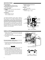
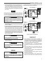
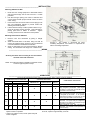
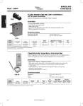
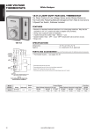
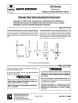
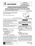
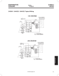
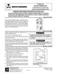
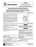
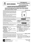
8A18Z-2
WHITE-RODGERS
Evaporative Cooler Control
INSTALLATION INSTRUCTIONS
Operator: Save these instructions for future use!
FAILURE TO READ AND FOLLOW ALL INSTRUCTIONS CAREFULLY
BEFORE INSTALLING OR OPERATING THIS CONTROL COULD CAUSE
PERSONAL INJURY AND/OR PROPERTY DAMAGE.
DESCRIPTION
This Evaporative Cooler Control has a rain-proof enclosure and can be used with either 120 VAC or 240 VAC
systems. It was designed for use with the White-Rodgers
1F51-619 or 1F51W-619 Thermostat to provide automatic temperature and ventilation control and remote fan
speed selection of an evaporative cooler with 2-speed
fan. The pump relay is automatically operated to allow
wetting of cooler pads before starting fan.
PRECAUTIONS
If in doubt about whether your wiring is millivolt, line, or low
voltage, have it inspected by a qualified heating and air
conditioning contractor, electrician, or someone familiar
with basic electricity and wiring.
Do not exceed the specification ratings.
All wiring must conform to local and national electrical
codes and ordinances.
This control is a precision instrument, and should be
handled carefully. Rough handling or distorting components could cause the control to malfunction.
WHITE-RODGERS DIVISION
EMERSON ELECTRIC CO.
9797 REAVIS ROAD
ST. LOUIS, MISSOURI 63123-5398
! CAUTION
To prevent electrical shock and/or equipment
damage, disconnect electric power to system, at
main fuse or circuit breaker box, until installation
is complete.
!
WARNING
Do not use on circuits exceeding specified voltage. Higher voltage will damage control and could
cause shock or fire hazard.
PART NO. 37-5918B
Printed in U.S.A.
Replaces 37-5918A
9909
SPECIFICATIONS
Electrical Ratings:
Input Voltage: 120 or 240 VAC, 60 Hz.
Operating Ambient Temperature Range:
40 to 150°F (5 to 65°C)
Power Consumption:
6 Watts nominal with all three relays energized
Fan Rating:
12 FLA., 72 LRA; 120 VAC
6 FLA., 36 LRA; 240 VAC
Pump Rating:
10 FLA., 60 LRA: 120 VAC
5 FLA., 30 LRA; 240 VAC
Combined Total Connected Load:
16 FLA., 120 VAC
8 FLA., 240 VAC
Mounting:
Four 9⁄32” Dia. holes
(2 1⁄2” x 5” center line to center line)
Dimensions:
6” wide x 8” high x 3” deep
Line
connections
8A18Z-2
The 8A18Z-2 Evaporative Cooler Control consists of
three relays and a low voltage transformer with dual
voltage primary. The pump relay is automatically operated, which allows the cooler pads to become wet before
the fan starts. This will eliminate the fan from blowing dust,
warm air, and odor on initial start-up. The fan relay
controls operation of the fan without the pump when the
thermostat subbase is in the vent position, and controls
operation of both fan and pump when the thermostat
subbase is in the cool position.
Pump
connections
N 120V
Low voltage
transformer
L2 240V
P2 120V P2 240V
Pump relay
F2 120V F2 240V
R
L1
W
Fan
connections
LO
P1
Y
HI
Low voltage
thermostat
connections
G
Fan
speed
relay
Fan timer
relay
Figure 1. Panel assembly
INSTALLATION
Flat washers
1. Remove cover screw. To remove cover, pull cover
outward at the top, then lift cover off the locating tabs
at the bottom of the case.
2. Remove panel assembly from case and discard packing material.
NOTE
Mounting holes
for four bolts
and washers
Panel mounting
screws
Cover
screw
Bolts
Place panel assembly in a safe location to prevent damage to the panel while installing the case.
3. Determine which knockouts will be used for electrical
conduits, then remove electrical knockouts from case
before mounting.
NOTE
Case
Panel
Cover
Figure 2. Installing control
If the larger knockout is to be removed, remove the
smaller knockout before removing the larger one.
4. To remove the knockouts, place a screwdriver on
the knockout at the location indicated by the arrow
(see fig. 3). Tap the screwdriver to pop the knockout
out of the case. If the knockout is not completely
removed, carefully use pliers to twist the knockout
until it comes out.
Figure 3. Electrical knockouts
2
INSTALLATION (cont’d)
5. Select an appropriate location for mounting the control. Position the case on a smooth flat surface in a
vertical position only (with electrical knockouts down).
Mount the case using flat washers and screws (not
provided) through the four mounting holes in the back
of the case.
All wiring should be done in accordance with local and
national electrical codes and ordinances.
120 VAC DIAGRAM
N
1F51-619 or 1F51W-619 THERMOSTAT
120V
R
HOT
W
Y
G
8A18Z-2
GND
NOTE
Install conduit, then run wiring and install the thermostat
according to thermostat installation instructions (included
with thermostat) before installing panel assembly in case.
N 120V
L2 240V
P2 120V
P2 240V
F2 120V
F2 240V
L1
P1
PUMP
RELAY
PUMP MOTOR
(120 V)
R
PUMP
RELAY
FAN SPEED
RELAY
FAN TIMER
RELAY
L0
W
Y
G
LO SPEED
FAN
L0
COM
! CAUTION
HI
HI
FAN
TIMER
HI SPEED RELAY
FAN
2-SPEED FAN
(120 V)
INTERNAL WIRING
FIELD INSTALLED WIRING
Non-metallic enclosure does not provide grounding between conduit connections. Use grounding
bushings and jumper wires to ensure proper
grounding of control.
ELECTRICAL CONNECTION
240 VAC DIAGRAM
1F51-619 or 1F51W-619 THERMOSTAT
L2
240V HOT
6. After wiring is run into case, bend the wires out slightly
so that the wires will be in front of the panel assembly
when it is installed.
7. Loosen the three panel mounting screws in the case
approximately one turn. Slide the two slots located at
the top of the panel assembly under the two mounting
screws at the top of the case. Lower the panel assembly into the case until the bottom mounting screw
protrudes through the keyhole slot on the panel. Slide
the panel assembly up toward the top of the case, then
hold the panel assembly in place while tightening all
three mounting screws.
L1
R
W
Y
G
8A18Z-2
HOT
GND
N 120V
L2 240V
P2 120V
P2 240V
F2 120V
F2 240V
L1
P1
PUMP
RELAY
PUMP MOTOR
(240 V)
R
PUMP
RELAY
FAN SPEED
RELAY
FAN TIMER
RELAY
L0
W
Y
G
LO SPEED
FAN
L0
COM
HI
2-SPEED FAN
(240 V)
HI
FAN
TIMER
HI SPEED RELAY
FAN
INTERNAL WIRING
FIELD INSTALLED WIRING
ELECTRICAL CONNECTION
Figure 4. Typical wiring diagrams
! CAUTION
Do not over tighten panel mounting screws to
avoid damage to the panel assembly.
8. Connect wires to proper terminals (see fig. 4 for typical
wiring connections).
! CAUTION
Do not press against panel assembly while tightening terminal screws to avoid damage to the
panel assembly.
9. Replace cover and test operation per the checkout
section.
WIRING
! CAUTION
To prevent electrical shock and/or equipment
damage, disconnect electric power to system at
main fuse or circuit breaker box until installation
is complete.
CHECKOUT
1. After mounting and wiring has been completed, set
thermostat switch to “OFF” position and fan switch to
“LO” position. Turn thermostat lever to “5” and thermostat switch to “COOL”. Nothing should happen provided the room temperature is below 95°F.
2. Turn thermostat lever to “1”. The pump should start
immediately, provided the room temperature is above
55°F.
3. After a time delay of 30 to 120 seconds to allow the
cooling pads to become soaked, the fan should start
running at low speed.
4. Turn fan switch to “HI” position. The fan should now be
operating on high speed.
5. Turn thermostat switch to “VENT” position. The pump
should stop immediately.
6. Turn the thermostat switch to “OFF” position. After a
delay of 3 to 30 seconds, the fan should stop running.
3
INSTALLATION INSTRUCTIONS
1F51-619
LOW VOLTAGE
EVAPORATIVE COOLER
THERMOSTAT
READ ALL INSTRUCTIONS CAREFULLY BEFORE INSTALLING OR OPERATING THIS CONTROL
The 1F51-619 low voltage thermostat is designed to
operate
with
the
White-Rodgers
8A18Z-1
Evaporative Cooler Control. For versatility, the
thermostat sub-base has a System Switch that lets
you select VENT, COOL, or OFF positions, while the
Fan Switch offers the selection of LOW or HIGH fan
speed.
____________________________________SPECIFICATIONS_____________________________________
Electrical Rating: 30V.A.C. Max.
Switch Action: SPST-Sealed Mercury Contacts
close on temperature rise.
Temperature Scale Range: 1 to 5 (Cooler to Warmer)
Differential: 1°F
Dimensions: 3¼” x 4½” x 1⅝”
________________________________________SAFETY_________________________________________
Installation of this equipment should be done by an experienced
service technician.
• Improper connections could cause shock
or fire hazard.
CAUTION: To prevent electrical shock and equipment
damage, disconnect electrical power to system at main fuse
or circuit breaker box, until installation is complete.
• All wiring must conform to local and
national electrical codes and ordinances.
WARNING: • Do not exceed the specification ratings on this
control. Check the manufacturer’s information
supplied with the associated product.
• Rough handling, tampering or distorting
components of control, could cause the
control to malfunction.
_____________________________SELECTING THERMOSTAT LOCATION__________________________
The proper location of the room thermostat is most
important to insure that it will provide a comfortable
home temperature. Observe the following general rules
when selecting a location:
1. Locate it about 5 ft. above the floor.
5.
Avoid locations close to air registers, or in the direct
path of air from them.
6.
Make sure there are no pipes or duct work in that
part of the wall chosen for the thermostat location.
7.
Never locate it in a room that is warmer or cooler
than the rest of the home.
Avoid location with lack of air circulation, such as
behind doors or alcoves.
2.
Install it on a partitioning wall, not on an outside wall.
3.
Never expose it to direct light from lamps, sun,
fireplaces, or any temperature radiating equipment.
8.
4.
Avoid locations close to doors that lead outside,
windows or adjoining outside walls.
9. The living or dining room is normally a good location
provided there is no cooking range or refrigerator on
opposite side of wall.
_____________________________________INSTALLATION______________________________________
Attaching Sub-Base to Wall
1.
2.
3.
4.
Route wire from cooling equipment to thermostat location
and pull wires through hole in wall so that 6 in. of cable
protrudes.
Pull wires through opening near center of sub-base and
connect wires beneath proper terminal screws as shown
under “wiring”.
Push excess wire into wall or switch box and plug up hole
with non-combustible material to prevent drafts from
affecting thermostat operation.
Fasten sub-base loosely to wall in position shown in Fig. 1
using two mounting screws provided. Level sub-base by
placing spirit level on bottom of sub-base. Tighten
mounting screws to secure sub-base in level position.
Mounting Thermostat to Sub-Base
1.
2.
3.
Remove cover from thermostat by pulling it straight
outward.
Attach thermostat base to sub-base, being sure that all
screws are tightened snugly since they serve as electrical
connections between thermostat and sub-base.
Snap on thermostat cover and set thermostat to desired
setting. The thermostat scale range has numbers from 1
through 5.
The number “1” represents the cooler
controlling temperature, and number “5” represents the
warmer controlling temperature.
________________________________________WIRING_________________________________________
All wiring should be done according to local and national
electrical codes and ordinances.
NOTE: See Instruction Sheet on 8A18Z-1 Evaporative Cooler
Control for typical system hook-up.
______________________________________OPERATIONS______________________________________
The chart below illustrates system and thermostat function during various modes of operation.
SUBBASE SWITCH POSITIONS
SYSTEM FUNCTIONS
COMPONENT OPERATION
FAN
SYSTEM
FAN
FAN
PUMP
TIMER RELAY
SPEED RELAY
RELAY
HI
LO
OFF
COOL
VENT
○
●
●
●
●
●
●
●
●
●
●
●
●
●
●
●
●
● Indicates switch position on thermostat sub-base and
system function in operation.
○ If left in “HI” position-no Fan, but fan speed relay will
remain energized.
●
●
NO FAN-NO PUMP-NO COOL
COOLING MODE-Pump relay and fan timer
relay energized by thermostat. Water begins
circulating on cooler pads, fan will start on low
speed after a short time-delay.*
COOLING MODE-Pump relay and fan timer
relay energized by thermostat. Fan speed relay
is energized by fan switch in “HI” position.
Water begins circulating on cooler pads, fan will
start on high speed after a short time-delay.*
VENT MODE-Fan timer relay energized by
thermostat. Fan speed relay is energized by
fan switch in “HI” position. Fan will start on high
speed after a short time-delay.
VENT MODE-Fan timer relay energized by
thermostat. Fan will start on low speed after a
short time-delay.*
* Fan timer relay energized in approximately one minute. When system
shuts off, it opens in approximately ½ minute.
If you need further information about this product, please write to
White-Rodgers Division, Emerson Electric Co.
9797 Reavis Road
St. Louis, MO 63123-5398
Attention: Technical Service Department