1
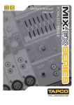
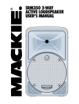
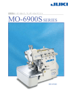
4FSJFT
TWO-WAY SOUND REINFORCEMENT LOUDSPEAKERS & SUBWOOFER
T
owner’s manual
SAFETY INSTRUCTIONS
12. Exposure to extremely high noise
levels may cause permanent hearing loss.
Individuals vary considerably in susceptibility
to noise-induced hearing loss, but nearly
everyone will lose some hearing if exposed
to sufficiently intense noise for a period of
time. The U.S. Government’s Occupational
Safety and Health Administration (OSHA) has specified the
permissible noise level exposures shown in the following chart.
1. Read these instructions.
2. Keep these instructions.
3. Heed all warnings.
4. Follow all instructions.
5. Do not use this apparatus near water.
6. Clean only with a dry cloth.
7. Do not block any ventilation openings. Install in accordance
with the manufacturer’s instructions.
8. Only use attachments/accessories specified by the
manufacturer.
9. Use only with a cart, stand, tripod, bracket, or table specified
by the manufacturer, or sold with the apparatus. When a
cart is used, use caution when moving the cart/apparatus
combination to avoid injury from tip-over.
10. Damage Requiring Service — This product should be serviced
only by qualified service personnel when:
According to OSHA, any exposure in excess of these permissible limits
could result in some hearing loss. To ensure against potentially dangerous
exposure to high sound pressure levels, it is recommended that all persons
exposed to equipment capable of producing high sound pressure levels
use hearing protectors while the equipment is in operation. Ear plugs or
protectors in the ear canals or over the ears must be worn when operating
the equipment in order to prevent permanent hearing loss if exposure is in
excess of the limits set forth here.
Duration Per Day Sound Level dBA,
In Hours
Slow Response
Typical
Example
A.Objects have fallen, or liquid has spilled into this product; or
B.This product has been exposed to rain; or
C.This product does not appear to operate normally or
exhibits a marked change in performance; or
8
90
6
92
D.This product has been dropped, or its chassis damaged.
4
95
3
97
2
100
1.5
102
1
105
0.5 110
0.25 or less
115
11. Servicing — The user should not attempt to service this
product beyond those means described in this operating
manual. All other servicing should be referred to an
authorized Tapco Service Center.
Packed garage concert
VW Bus Peace Train
Cranked psychedelic tunes
High speed chase on C.H.I.P.s
Loudest parts at a Heavy Metal concert
Contents
SAFETY INSTRUCTIONS................................................2
Introduction................................................................3
Getting Started..........................................................4
Hookup Diagrams......................................................5
Placement..................................................................7
Room Acoustics....................................................7
Protection...................................................................8
HF Protection........................................................8
Amplifier Power.....................................................8
Appendix A: Service Information...........................10
Warranty Service................................................10
Troubleshooting..................................................10
Repair..................................................................10
Appendix B: Connections .....................................11
Appendix C: Specifications ...................................12
TAPCO LIMITED WARRANTY.....................................15
Don’t forget to visit our website at www.tapcogear.com
for more information about this and other TAPCO products.
What me, read a manual?
Before you begin, please make sure you read the Safety Instructions on page 2 and
Getting Started on page 4.
Your new TAPCO® Series 69 loudspeakers are designed to set up quickly and operate
easily. We know it’s often seen as a sign of weakness to read a manual, along with asking
for directions when lost, but we hope you will read the rest of the manual, at least while
nobody is looking.
It is important to keep your receipt in a safe place, and not a bad idea to write your
product information here for future reference (i.e., insurance claims, tech support, return
authorization, etc.).
Product Serial #:
Speaker 2
Speaker 1
Purchased at:
Date of purchase:
Introduction
Thank you for choosing TAPCO Series 69 sound reinforcement loudspeakers. The TAPCO
product line hails back to the days of TAPCO Corporation, Greg Mackie’s first company.
TAPCO revolutionized the audio industry back in 1969 with the very first 6-channel mixer
specifically designed for keyboards and rock ‘n’ roll.
In essence, TAPCO redefined the price/performance ratio and made high-quality
professional audio equipment accessible to virtually anyone. Today, TAPCO is reborn
with the same ideals and is backed by the world-class engineering and manufacturing
horsepower of LOUD Technologies. The Series 69 were designed by the same experts
responsible for Mackie’s best-selling SRM450 active loudspeakers and tweaked by the
expert loudspeaker engineers at EAW.
The TAPCO Series 69 loudspeakers feature precision low-frequency woofers and 1-inch
high-output compression drivers (except for the subwoofer) with built-in protection circuitry.
These versatile loudspeakers can be used in a variety of applications, including live
sound reinforcement and music playback.
Here’s a quick look at the TAPCO Series 69 features:
6912
6915
• Mackie-designed 2-way full-range loudspeaker
• Mackie-designed 2-way full-range loudspeaker
• 1” HF compression driver
• 1” HF titanium dome compression driver
• 12” high-precision LF driver, vented
• 15” high-precision LF driver, vented
• Built-in HF driver protection circuitry
• Built-in HF driver protection circuitry
• 250 watts continuous power handling
• 300 watts continuous power handling
• 8 ohm impedance
• 8 ohm impedance
• Speakon™ and 1/4” inputs
• Speakon™ and 1/4” inputs
• Rugged vinyl covering
• Rugged vinyl covering
• Protective corner bumpers
• Protective corner bumpers
• Pole mount socket on bottom of enclosure
• Pole mount socket on bottom of enclosure
Part No. 0011359 Rev. B 9/06
©2006 LOUD Technologies Inc. All Rights Reserved.
6925
6918s
• Mackie-designed 2-way full-range loudspeaker
• 18” subwoofer
• 1” HF compression driver
• 450 watts continuous power handling
• Dual 15” high-precision LF drivers, vented
• 8 ohm impedance
• Built-in HF driver protection circuitry
• Speakon™ and 1/4” inputs
• 600 watts continuous power handling
• Durable painted enclosure
• 8 ohm impedance
• Pole mount socket on top of enclosure
• Speakon™ and 1/4” inputs
• Rugged composite vinyl covering
• Protective corner bumpers
Getting Started
The following steps will
help you set up your
loudspeakers quickly.
1. Make all initial connections with the power
switches OFF on all equipment. Make sure the
master volume, level, or gain controls are all the
way down.
4. If you are using the 6918s subwoofer with one of
the full-range loudspeakers, connect the 1/4" OUT
or the Speakon LINK EXTENSION to the subwoofer’s
input.
2. Connect the line-level outputs from your mixing
console (or other signal source) to the inputs of
your power amplifier.
5. Turn on your mixing console (or other signal
source).
3. Connect the “Speaker Output” from your
power amplifier (or powered mixer) to the INPUT
connector on the Series 69 (1/4" or Speakon jack).
6. Turn on the amplifier. Turn up its volume or gain
control(s) as recommended by the manufacturer.
7. Start the signal source, whether it be speaking
into a microphone or starting a CD player. Adjust
the volume controls on the mixer (or other signal
source) for normal operation.
Hookup Diagrams
Stereo
Power Amplifier
Left
Line level
Output
Right
Line level
Output
Mixer or
Preamplifier
MAIN OUT
CTRL ROOM OUT
AUX SEND
0
0
1
0
2
1
U
EQ
0
3
2
U
EQ
5/6
4
3
U
EQ
4
U
U
U
U
U
U
U
U
U
EQ
7/8
TAPE
AUX
SEND
AUX
U
PAN
U
LEVEL
SEND
AUX
U
PAN
U
LEVEL
SEND
U
U
LEVEL
SEND
SEND
U
LEVEL
U
LEVEL
9/10
AUX
SEND
U
BAL
PAN
U
7/8
AUX
AUX
U
PAN
PHONES
11/12
MAIN
5/6
U
9/10
AUX
SEND
U
BAL
U
LEVEL
LEVEL
6912’s with a Mixer and Power Amplifier
AUX
SEND
U
BAL
U
MAIN
MIX
11/12
BAL
U
LEVEL
Stereo
Power Amplifier
Left
Line level
Output
Right
Line level
Output
Mixer or
Preamplifier
MAIN OUT
You can use the 1/4" outputs
or the Neutrik “Link Extension”
connectors as “Thru” connections
to daisy-chain the signal to
another loudspeaker.
CTRL ROOM OUT
AUX SEND
0
0
1
0
2
1
U
EQ
U
3
2
U
EQ
U
U
0
3
U
EQ
U
U
5/6
4
4
U
EQ
7/8
TAPE
U
SEND
AUX
U
PAN
U
LEVEL
SEND
U
U
LEVEL
U
SEND
U
LEVEL
SEND
U
LEVEL
SEND
U
LEVEL
9/10
AUX
U
BAL
PAN
U
7/8
AUX
AUX
PAN
U
MAIN
U
AUX
PAN
PHONES
11/12
U
U
5/6
AUX
9/10
SEND
U
BAL
U
LEVEL
11/12
AUX
SEND
U
LEVEL
MAIN
MIX
AUX
U
BAL
SEND
BAL
U
LEVEL
6912’s with a Mixer and Power Amplifier, Daisy-Chaining
6912
Plays the Mid and
High Frequencies
From Output
(or Link Extension)
6912
Plays the Mid and
High Frequencies
To Input
To Input
To Input
To Input
Stereo
Power
Amplifier
Pole
Mount
6918s
Plays the Low
Frequencies
MAIN OUT
Pole
Mount
CTRL ROOM OUT
AUX SEND
0
0
1
0
2
1
U
EQ
0
3
2
U
EQ
5/6
4
3
U
EQ
4
U
U
U
U
U
U
U
U
U
EQ
7/8
AUX
SEND
AUX
U
PAN
U
LEVEL
SEND
AUX
U
PAN
U
LEVEL
SEND
U
LEVEL
SEND
U
LEVEL
7/8
SEND
U
LEVEL
9/10
AUX
U
BAL
PAN
U
MAIN
AUX
AUX
U
PAN
PHONES
11/12
6918s
Plays the Low
Frequencies
U
5/6
U
9/10
TAPE
From Output
(or Link Extension)
SEND
AUX
U
BAL
U
LEVEL
11/12
SEND
AUX
U
BAL
U
LEVEL
SEND
BAL
U
LEVEL
MAIN
MIX
The 6912’s can be used with the 6918s
subwoofers to create an incredibly powerful system.
The full-range stereo signal from the mixer and
power amplifier go the the inputs of the left and
right 6912’s.
The outputs from the 6912’s are connected to
the inputs of the 6918s subwoofers, whose internal
low-pass filter allows the subwoofers to reproduce
only the lowest frequencies.
The 6912’s can be pole mounted on top of the
6918s subwoofers as shown.
6912’s Daisy-Chained with two 6918s Subwoofers
Placement
Your new Series 69 loudspeakers are
designed to sit on the floor or a tabletop. In
addition, the 6912 and 6915 are designed to
be pole-mounted or fit on a standard tripod
speaker stand. The 6925 and 6918s ARE NOT
designed to be pole-mounted.
Warning: The Series 69
enclosures have no rigging
points and are not suitable
for rigging. NEVER attempt to
suspend any of the Series 69
enclosures by its handles.
• Highly reverberant rooms, like many gymnasiums
and auditoriums, are a nightmare for sound system
intelligibility. Multiple reflections off the hard walls,
ceiling, and floor play havoc with the sound.
Depending on the situation, you may be able to
take some steps to minimize the reflections, such as
putting carpeting on the floors, closing draperies to
cover large glass windows, or hanging tapestries or
other materials on the walls to absorb some of the
sound.
However, in most cases, these remedies are not
possible or practical. So what do you do? Making
the sound system louder generally doesn’t work
because the reflections become louder, too.
The best approach is to provide as much direct
sound coverage to the audience as possible. The
farther away you are from the speaker, the more
prominent will be the reflected sound.
Use more speakers strategically placed so they are
closer to the back of the audience. If the distance
between the front and back speakers is more than
about 100 feet, you should use a delay processor
to time-align the sound. (Since sound travels about
one foot per millisecond, it takes about 1/10 of a
second to travel 100 feet).
As with any loudspeakers, protect them
from moisture. If you are setting them up
outdoors, make sure they are under cover if
you expect rain.
Room Acoustics
The Series 69 loudspeakers are designed
to sound as neutral as possible. However,
room acoustics play a crucial role in the
overall performance of a sound system.
Here are some placement tips to get
the best performance from the Series 69
loudspeakers:
• Avoid placing loudspeakers in the corners of a
room. This increases the low-frequency output and
can cause the sound to be muddy and indistinct.
• Avoid placing loudspeakers against a wall. This,
too, increases the low-frequency output, though
not as much as corner placement. However, if you
do need to reinforce the low frequencies, this is a
good way to do it.
• Avoid placing the speakers directly on a hollow
stage floor. A hollow stage can resonate at
certain frequencies, causing peaks and dips in
the frequency response of the room. It’s better to
place the loudspeakers on a sturdy table or tripod
stands.
• Position the loudspeakers so the high-frequency
drivers are two to four feet above ear level for
the audience (make allowances for a standing/
dancing-in-the-aisles audience). High frequencies
are highly directional and tend to be absorbed
much easier than lower frequencies. By providing
direct line-of-sight from the loudspeakers to the
audience, you increase the overall brightness and
intelligibility of the sound system.
ADDITIONAL TIDBITS OF WIDSDOM:
• Never listen to loud music for prolonged periods.
Please see the Safety Instructions on page 2 for
information on hearing protection.
• When you shut down your equipment, turn off the
amplifiers first to prevent thumps and other noises
generated by any upstream equipment from
coming out the speakers. When powering up, turn
on the amplifiers last.
• Save the shipping boxes and packing materials!
You may need them someday. Besides, your cat
will love playing in them and jumping out at you
unexpectedly. Remember to pretend like you are
surprised!
• Save your sales receipt in a safe place.
• Also record the serial numbers in the space
provided on page 3, along with where and when
you bought them.
Protection
HF Protection
A protection circuit is built into the
6912, 6915, and 6925 to protect their highfrequency compression drivers from excessive
power. When tripped, the protection circuit
substantially reduces the power to the
HF driver. After the driver cools to a safe
operating temperature, the protection
circuit resets and normal operation resumes.
However, if the protection circuit senses
excessive power, it will trip again. In this case,
it is necessary to reduce the power to the
loudspeaker by either turning down the gain
controls on the power amplifier or turning
down the master volume control on the mixer
or other sound source.
CAUTION: The protection
circuit is designed to
protect the HF driver under
reasonable and sensible
conditions. Should you
choose to ignore the warning
signs (i.e., frequent clip LED indications on
the mixer or power amplifier, excessive
distortion), you can still damage the drivers
in the Series 69 loudspeakers by overdriving
them past their recommended amplifier
power-handling ratings, or past the point of
amplifier clipping. Such damage is beyond
the scope of the warranty.
Amplifier Power
We give you two power-handling
numbers for the Series 69 loudspeakers:
continuous amd program. So how much
power do you really need to drive the Series
69 loudspeakers?
The answer to that question depends
on what type of program material you are
running through the system and how loud it
needs to be.
Some audio signals have lots of
momentary peaks whose amplitudes
extend far above the average overall level
of the program. Percussion instruments are a
good example of this. Other types of signals,
like highly compressed rock music, have
a higher average signal level with fewer
peaks. Speech reinforcement requires less
power overall, but involves large momentto-moment variations in level.
Assuming you want to use the full
capability of the loudspeaker, and the
program contains at least some momentary
peaks, we recommend that you use
an amplifier that is rated at twice the
continuous power rating of the loudspeaker
(into 8 ohms). For the 6912s, this would be
250 watts x 2 = 500 watts per channel into
8 ohms. This insures that the amplifier can
reproduce peaks that are 6 dB higher than
the continuous (rms) power-handling rating
before clipping occurs.
Recommended Power Ratings
6912
500 watts into 8 ohms (250 watts rms x 2)
6915
600 watts into 8 ohms (300 watts rms x 2)
6925
1200 watts into 8 ohms (600 watts rms x 2)
6918s
900 watts into 8 ohms (450 watts rms x 2)
Preventing Loudspeaker Damage
Speaking of clipping, this is likely
the number one cause of damage to
loudspeakers. Clipping occurs when the
signal at the output of any device in the
system (not just the amplifier) reaches its
maximum level. The input signal to the
device may continue to increase, but the
output simply stops, and is characterized by
a “flat-top” appearance to the waveform.
Normal Sine Wave Signal ☺
Clipped Sine Wave Signal Clipping interrupts the motion of the
transducer, creating distortion and excessive
heat in the driver, which can damage it
over time.
Some folks think that if they use a power
amplifier whose power rating is below
the maximum power-handling rating of
the loudspeaker, then they can’t possibly
damage the loudspeaker. But if the amplifier
is driven into clipping, even a lower power
amplifier can damage the loudspeaker.
The bottom line is that to prevent
damage to the loudspeakers, you must
have a properly operating sound system.
Proper operation of a sound system includes
being aware of the types of audio signals
being reproduced, controlling the output
levels accordingly, and operating all the
devices in the system so that no clipping
occurs within the signal chain.
Appendix A: Service Information
Warranty Service
Repair
Details concerning Warranty Service are spelled
out in the Warranty section on page 15.
If you think your TAPCO Series 69 loudspeaker has
a problem, please do everything you can to confirm
it before calling for service. Doing so might save you
from the deprivation of your loudspeaker and the
associated suffering.
These may sound obvious to you, but here are
some things you can check. Read on.
Service for TAPCO products is available at a
factory-authorized service center. Service for TAPCO
products living outside the United States can be
obtained through local dealers or distributors.
If your loudspeaker needs service, follow these
instructions:
1. Review the preceding troubleshooting suggestions.
Please.
Troubleshooting
No sound
• Are the level controls on the mixer or amplifier
turned all the way down? Follow the procedures
in the “Getting Started” section on page 4 to
verify that all the volume controls in the system are
properly adjusted.
• Is the signal source working (and making union
scale)?
• Are all the connections good and sound? Make
sure all the connecting cables are in good repair
and securely connected at both ends.
One side is way louder than the other!
• Are the level controls set the same for both
channels on the mixer and amplifier?
• Check the PAN control on the signal source. It
may be turned too far to one side. If you’re using
a stereo signal source, it may be delivering an outof-balance stereo signal.
• Try swapping sides: Switch the speaker cables
coming from the amplifier at the amplifier end. If
the other side is louder now, the problem is with
the amplifier, the mixer, or the signal source.
Poor bass performance
• Check the polarity of the connections between
the amplifier and the loudspeakers. You may have
your positive and negative connections reversed
at one end of one cable.
Bad sound
• Is the input connector plugged completely into
the jack? Make sure it is plugged all the way in.
• Is it loud and distorted? Reduce the signal level at
the mixer.
• If possible, listen to the signal source with
headphones plugged into the preamp stage. If it
sounds bad there, it’s not the loudspeaker.
10
• Keep practicing.
2. Call Tech Support at 1-877-827-2669, 7 am to 5
pm PST, to explain the problem and obtain a
Service Request Number. Have your loudspeaker’s
serial number ready. You must have a Service
Request Number before you can obtain factoryauthorized service.
3. Keep this owner’s manual. We don’t need it to
repair the loudspeaker.
4. Pack the loudspeaker in its original package,
including endcaps and box. This is VERY
IMPORTANT. When you call for the Service Request
Number, please let Tech Support know if you need
new packaging. TAPCO is not responsible for
any damage that occurs due to non-factory
packaging.
5. Include a legible note stating your name,
shipping address (no P.O. boxes), daytime phone
number, Service Request Number, and a detailed
description of the problem, including how we can
duplicate it.
6. Write the Service Request Number in BIG PRINT on
top of the box. Units sent without the Service Request
Number will be refused.
7. Tech Support will tell you where to ship the
loudspeaker for repair. We suggest insurance for all
forms of cartage.
8. You will need to contact the authorized service
center for their latest turn-around times. The
loudspeaker must be packaged in its original
packing box, and must have the Service Request
Number on the box. Once it’s repaired, the
authorized service center will ship it back, pre-paid
(if it was a warranty repair).
Note: Under the terms of the warranty, you must ship
or drop-off the unit to an authorized service center.
The return ground shipment is covered for those units
deemed by us to be under warranty.
Note: You must have a sales receipt from an
authorized TAPCO dealer to qualify for a warranty
repair.
Care and Maintenance
Your TAPCO loudspeakers will provide many years
of reliable service if you follow these simple guidelines:
• Avoid exposing the loudspeakers to moisture. If
they are set up outdoors, be sure they are under
cover if you expect rain.
• Avoid exposure to extreme cold (below
freezing temperatures). If you must operate the
loudspeakers in a cold environment, warm up the
voice coils slowly by sending a low-level signal
through them for about 15 minutes prior to highpower operation.
• Use a damp cloth with a mild soap solution to
clean the cabinets. Avoid getting moisture into
any of the openings of the cabinet, particularly
where the drivers are located.
Appendix B: Connections
Use heavy gauge, stranded wire for connecting
a speaker to the output of a power amplifier. Do not
use a guitar cord to make this connection. They
aren’t designed to handle the high currents produced
by a power amplifier and can overheat.
As the distance between the amplifier and
speakers increases, the thickness of the wire should
also increase. Speaker wire has resistance, and when
electricity passes through a resistor, power is lost. The
thicker the wire, the less resistance it offers, and the
more power actually gets to the speaker.
1/4" TS Phone Plugs and Jacks
“TS” stands for Tip-Sleeve, the two connections
available on a mono 1/4" phone jack or plug.
They are used for unbalanced signals and speaker
connections.
1/4" TS Wiring:
Sleeve = Cold (–)
Tip = Hot (+)
SLEEVE
SLEEVE
TIP
NL4-Type Plugs and Jacks
This connector is compatible with the popular
Neutrik® Speakon® 4-pole plugs. These connectors
are designed to handle the higher currents produced
by amplifiers, and have a locking feature to prevent
accidental disconnections. Simply line up the tabs
on the plug with the jack on the Series 69 connector
panel, push it in, and rotate it 1/4 turn to the right to
lock it in place.
NL4 Wiring:
Pin 1 – = Cold (–)
Pin 1 + = Hot (+)
Pin 2 – = No Connection
Pin 2 + = No Connection
1–
1+
COLD
HOT
1–
1+
2+
2–
TIP
TIP
SLEEVE
Lonely? Looking for that special someone? Do you have a question about
your TAPCO loudspeaker?
Please call our Technical Support chaps at 1-877-827-2669, Monday to Friday, from 7 AM to 5 PM PST.
After hours, visit www.tapcoworld.com and look under Support, or e-mail us at techmail@tapcogear.com
Flash From The Past
“Good morning. What we have in mind is breakfast in bed for 400,000!”
– Wavy Gravy at the Woodstock Festival & Concert, 1969
11
Appendix C: Specifications
6915 Specifications
System
6912 Specifications
System
System Type: Two-way, full-range loudspeaker
Frequency Range (–10 dB):
49 Hz to 18 kHz
Sensitivity (1W @ 1m):
99.9 dB SPL
Nominal Impedance:
8 ohms
Power Handling:
250 watts continuous
500 watts program
Transducers
Transducers
Low Frequency:
High Frequency:
12 in/305 mm woofer, vented
1 in/25 mm tweeter,
Low Frequency:
High Frequency:
15 in/381 mm woofer, vented
1 in/25 mm tweeter,
Physical
Physical
Input Connectors:
Enclosure: Dimensions:
Height: Width: Depth: Weight: Mounting:
System Type: Two-way, full-range loudspeaker
Frequency Range (–10 dB):
47 Hz to 18 kHz
Sensitivity (1W @ 1m):
101.1 dB SPL
Nominal Impedance:
8 ohms
Power Handling:
300 watts continuous
600 watts program
One 1/4” TS jack,
one Speakon jack, paralleled
Wood with textured black PVC vinyl covering
25.6 in/65.1 cm
17.8 in/45.1 cm
15.6 in/39.6 cm
49 lb/22 kg
Pole-mountable
Input Connectors:
Enclosure: Dimensions:
Height: Width: Depth: Weight: Mounting:
One 1/4” TS jack,
one Speakon jack, paralleled
Wood with textured black PVC vinyl covering
28.1 in/71.4 cm
17.8 in/45.1 cm
15.6 in/39.6 cm
51 lb/23 kg
Pole-mountable
6912 Dimensions
17.8 in/
45.1 cm
25.6 in/
65.1 cm
DESIGNED IN WOODINVILLE, WA, USA
MANUFACTURED IN CHINA.
"TAPCO" IS A REGISTERED TRADEMARK
OF LOUD TECHNOLOGIES INC.
©2006 LOUD TECHNOLOGIES INC.
17.8 in/
45.1 cm
15.6 in/
39.6 cm
13.8 in/
34.9 cm
6915 Dimensions
17.8 in/
45.1 cm
28.1 in/
71.4 cm
TAPCO 69 SERIES / 6915
DESIGNED IN WOODINVILLE, WA, USA
MANUFACTURED IN CHINA.
"TAPCO" IS A REGISTERED TRADEMARK
OF LOUD TECHNOLOGIES INC.
©2006 LOUD TECHNOLOGIES INC.
IMPEDANCE
8 Ohm
POWER
300 Watts
IN
OUT
LINK
INPUT
12
EXTENSION
17.8 in/
45.1 cm
15.6 in/
39.6 cm
13.8 in/
34.9 cm
6925 Specifications
System
6918s Specifications
System
System Type: Two-way, full-range loudspeaker
Frequency Range (–10 dB):
51 Hz to 18 kHz
Sensitivity (1W @ 1m):
102.9 dB SPL
Nominal Impedance:
8 ohms
Power Handling:
600 watts continuous
1200 watts program
Transducers
Subwoofer
37 Hz to 220 Hz
98.3 dB SPL
8 ohms
450 watts continuous
900 watts program
Transducers
Low Frequency: Two 15 in/381 mm woofers, vented
High Frequency:
1 in/25 mm tweeter,
Physical
Input Connectors:
Enclosure: Dimensions:
Height: Width: Depth: Weight: System Type:
Frequency Range (–10 dB):
Sensitivity (1W @ 1m):
Nominal Impedance:
Power Handling:
One 1/4” TS jack,
one Speakon jack, paralleled
Wood with textured black PVC vinyl covering
43.9 in/111.5 cm
16.8 in/42.5 cm
15.6 in/39.6 cm
75 lb/34 kg
Low Frequency:
18 in/457 mm woofer, vented
Physical
Input Connectors:
Enclosure: Dimensions:
Height: Width: Depth: Weight: Mounting:
One 1/4” TS jack,
one Speakon jack, paralleled
Wood with durable black paint
23.9 in/60.7 cm
20.3 in/51.4 cm
21.3 in/54.0 cm
70 lb/32 kg
Pole-mount on top
6925 Dimensions
43.9 in/
111.5 cm
16.8 in/
42.5 cm
TAPCO 69 SERIES / 6925
DESIGNED IN WOODINVILLE, WA, USA
MANUFACTURED IN CHINA.
"TAPCO" IS A REGISTERED TRADEMARK
OF LOUD TECHNOLOGIES INC.
©2006 LOUD TECHNOLOGIES INC.
IMPEDANCE
8 Ohm
POWER
600 Watts
IN
OUT
LINK
INPUT
EXTENSION
16.8 in/
42.5 cm
15.6 in/
39.6 cm
6918s Dimensions
13.3 in/
33.7 cm
20.3 in/
51.6 cm
23.9 in/
60.7 cm
TAPCO 69 SERIES / 6918s
DESIGNED IN WOODINVILLE, WA, USA
MANUFACTURED IN CHINA.
"TAPCO" IS A REGISTERED TRADEMARK
OF LOUD TECHNOLOGIES INC.
©2006 LOUD TECHNOLOGIES INC.
IMPEDANCE
8 Ohm
POWER
450 Watts
IN
OUT
LINK
INPUT
EXTENSION
20.3 in/
51.4 cm
21.3 in/
54.0 cm
15.5 in/
39.3 cm
13
Disclaimer
Since we are always striving to make our products
better by incorporating new and improved materials,
components, and manufacturing methods, we
reserve the right to change these specifications at
any time without notice.
“TAPCO” is a registered trademark of LOUD
Technologies Inc. All other brand names mentioned
are trademarks or registered trademarks of their
respective holders, and are hereby acknowledged.
©2006 LOUD Technologies Inc. All Rights Reserved.
14
TAPCO LIMITED WARRANTY
A. LOUD Technologies Inc. warrants all materials,
workmanship and proper operation of this TAPCO
product for a period of one year from the original
date of purchase. If any defects are found in the
materials or workmanship, or if the product fails to
function properly during the applicable warranty
period, LOUD Technologies, at its option, will repair
or replace the product. This warranty applies only
to equipment sold and delivered within the U.S.
by LOUD Technologies or its authorized dealers.
or replaced within thirty days of receipt. LOUD
Technologies and its authorized service centers
may use refurbished parts for repair or replacement
of any product. Products returned to LOUD
Technologies that do not meet the terms of this
Warranty will not be repaired until payment is
received for labor, materials, return freight, and
insurance. Products repaired under warranty will be
returned freight prepaid by LOUD Technologies to
any location within the boundaries of the USA.
B. Failure to register online or return the product
registration card will not void the one-year warranty.
G. LOUD Technologies warrants all repairs performed
for 90 days or for the remainder of the original
warranty period. This warranty does not extend to
damage resulting from improper installation, misuse,
neglect or abuse, or to exterior appearance. This
warranty is recognized only if the inspection seals
and serial number on the unit have not been
defaced or removed.
C. Service and repairs of TAPCO products are to
be performed only at a factory-authorized
service center. Unauthorized service, repairs, or
modification will void this warranty. To obtain
repairs under warranty, you must have a copy
of your sales receipt from the authorized TAPCO
dealer where you purchased the product. It
is necessary to establish purchase date and
determine whether your TAPCO product is within
the warranty period.
D. To obtain factory-authorized service:
1. Call TAPCO Technical Support at 877/827-2669,
7 AM to 5 PM Monday through Friday (Pacific time)
to get a Service Request Number. Products returned
without a Service Request Number will be refused.
2. Pack the product in its original shipping carton.
Also include a note explaining exactly how to
duplicate the problem, a copy of the sales receipt
with price and date showing, and your return
street address (no P.O. boxes or route numbers,
please!). If we cannot duplicate the problem or
establish the starting date of your Limited Warranty,
we may, at our option, charge for service time.
3. Ship the product in its original shipping carton,
freight prepaid, to the authorized service center.
The address of your closest authorized service
center will be given to you by Technical Support.
IMPORTANT: Make sure that the Service Request
Number is plainly written on the shipping carton.
E. LOUD Technologies Inc. reserves the right to
inspect any products that may be the subject of
any warranty claims before repair or replacement
is carried out. LOUD Technologies may, at their
option, require proof of the original date of
purchase in the form of a dated copy of the
original dealer’s invoice or sales receipt. Final
determination of warranty coverage lies solely
with LOUD Technologies Inc.
F. TAPCO products returned to one of the LOUD
Technologies factory-authorized service centers
and deemed eligible for repair or replacement
under the terms of this warranty will be repaired
H. LOUD Technologies assumes no responsibility for
the quality or timeliness of repairs performed by
Authorized TAPCO Service Centers.
I. This warranty is extended to the original purchaser
and to anyone who may subsequently purchase
this product within the applicable warranty period.
A copy of the sales receipt is required to obtain
warranty repairs.
J. This is your sole warranty. LOUD Technologies Inc.
does not authorize any third party, including any
dealer or sales representative, to assume any
liability on behalf of LOUD Technologies or to make
any warranty for LOUD Technologies.
K. THE WARRANTY GIVEN ON THIS PAGE IS THE SOLE
WARRANTY GIVEN BY LOUD TECHNOLOGIES INC.
AND IS IN LIEU OF ALL OTHER WARRANTIES, EXPRESS
AND IMPLIED, INCLUDING THE WARRANTIES OF
MERCHANTABILITY AND FITNESS FOR A PARTICULAR
PURPOSE. THE WARRANTY GIVEN ON THIS PAGE
SHALL BE STRICTLY LIMITED IN DURATION TO ONE
YEAR FROM THE DATE OF ORIGINAL PURCHASE
FROM AN AUTHORIZED TAPCO DEALER. UPON
EXPIRATION OF THE APPLICABLE WARRANTY
PERIOD, LOUD TECHNOLOGIES INC. SHALL HAVE
NO FURTHER WARRANTY OBLIGATION OF ANY
KIND. LOUD TECHNOLOGIES INC. SHALL NOT
BE LIABLE FOR ANY INCIDENTAL, SPECIAL, OR
CONSEQUENTIAL DAMAGES THAT MAY RESULT
FROM ANY DEFECT IN THE TAPCO PRODUCT OR
ANY WARRANTY CLAIM. Some states do not
allow exclusion or limitation of incidental, special,
or consequential damages or a limitation on
how long warranties last, so some of the above
limitations and exclusions may not apply to you.
This warranty provides specific legal rights and you
may have other rights which vary from state to state.
Please keep your sales receipt in a safe place.
15