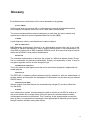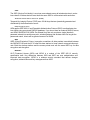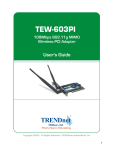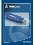
1
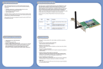
EZ Connect™ N Pro
Draft 11n Wireless PCI Adapter
SMCWPCI-N2
LIMITED WARRANTY
Limited Warranty Statement: SMC Networks, Inc. (“SMC”) warrants its products to be free from
defects in workmanship and materials, under normal use and service, for the applicable warranty
term. All SMC products carry a standard 90-day limited warranty from the date of purchase from
SMC or its Authorized Reseller. SMC may, at its own discretion, repair or replace any product not
operating as warranted with a similar or functionally equivalent product, during the applicable
warranty term. SMC will endeavor to repair or replace any product returned under warranty within
30 days of receipt of the product. The standard limited warranty can be upgraded to a Limited
Lifetime* warranty by registering new products within 30 days of purchase from SMC or its
Authorized Reseller. Registration can be accomplished via the enclosed product registration card
or online via the SMC website. Failure to register will not affect the standard limited warranty. The
Limited Lifetime warranty covers a product during the Life of that Product, which is defined as the
period of time during which the product is an “Active” SMC product. A product is considered to be
“Active” while it is listed on the current SMC price list. As new technologies emerge, older
technologies become obsolete and SMC will, at its discretion, replace an older product in its
product line with one that incorporates these newer technologies. At that point, the obsolete
product is discontinued and is no longer an “Active” SMC product. A list of discontinued products
with their respective dates of discontinuance can be found at:
http://www.smc.com/index.cfm?action=customer_service_warranty.
All products that are replaced become the property of SMC. Replacement products may be either
new or reconditioned. Any replaced or repaired product carries either a 30-day limited warranty or
the remainder of the initial warranty, whichever is longer. SMC is not responsible for any custom
software or firmware, configuration information, or memory data of Customer contained in, stored
on, or integrated with any products returned to SMC pursuant to any warranty. Products returned
to SMC should have any customer-installed accessory or add-on components, such as expansion
modules, removed prior to returning the product for replacement. SMC is not responsible for these
items if they are returned with the product. Customers must contact SMC for a Return Material
Authorization number prior to returning any product to SMC. Proof of purchase may be required.
Any product returned to SMC without a valid Return Material Authorization (RMA) number clearly
marked on the outside of the package will be returned to customer at customer’s expense. For
warranty claims within North America, please call our toll-free customer support number at (800)
762-4968. Customers are responsible for all shipping charges from their facility to SMC. SMC is
responsible for return shipping charges from SMC to customer.
WARRANTIES EXCLUSIVE: IF AN SMC PRODUCT DOES NOT OPERATE AS WARRANTED
ABOVE, CUSTOMER’S SOLE REMEDY SHALL BE REPAIR OR REPLACEMENT OF THE
PRODUCT IN QUESTION, AT SMC’S OPTION. THE FOREGOING WARRANTIES AND
REMEDIES ARE EXCLUSIVE AND ARE IN LIEU OF ALL OTHER WARRANTIES OR
CONDITIONS, EXPRESS OR IMPLIED, EITHER IN FACT OR BY OPERATION OF LAW,
STATUTORY OR OTHERWISE, INCLUDING WARRANTIES OR CONDITIONS OF
MERCHANTABILITY AND FITNESS FOR A PARTICULAR PURPOSE. SMC NEITHER
ASSUMES NOR AUTHORIZES ANY OTHER PERSON TO ASSUME FOR IT ANY OTHER
LIABILITY IN CONNECTION WITH THE SALE, INSTALLATION, MAINTENANCE OR USE OF
ITS PRODUCTS. SMC SHALL NOT BE LIABLE UNDER THIS WARRANTY IF ITS TESTING
AND EXAMINATION DISCLOSE THE ALLEGED DEFECT IN THE PRODUCT DOES NOT EXIST
OR WAS CAUSED BY
CUSTOMER’S OR ANY THIRD PERSON’S MISUSE, NEGLECT, IMPROPER INSTALLATION
OR TESTING, UNAUTHORIZED ATTEMPTS TO REPAIR, OR ANY OTHER CAUSE BEYOND
THE RANGE OF THE INTENDED USE, OR BY ACCIDENT, FIRE, LIGHTNING, OR OTHER
HAZARD.
i
LIMITATION OF LIABILITY: IN NO EVENT, WHETHER BASED IN CONTRACT OR TORT
(INCLUDING NEGLIGENCE), SHALL SMC BE LIABLE FOR INCIDENTAL, CONSEQUENTIAL,
INDIRECT, SPECIAL, OR PUNITIVE DAMAGES OF ANY KIND, OR FOR LOSS OF REVENUE,
LOSS OF BUSINESS, OR OTHER FINANCIAL LOSS ARISING OUT OF OR IN CONNECTION
WITH THE SALE, INSTALLATION, MAINTENANCE, USE, PERFORMANCE, FAILURE, OR
INTERRUPTION OF ITS PRODUCTS, EVEN IF SMC OR ITS AUTHORIZED RESELLER HAS
BEEN ADVISED OF THE POSSIBILITY OF SUCH DAMAGES. SOME STATES DO NOT ALLOW
THE EXCLUSION OF IMPLIED WARRANTIES OR THE LIMITATION OF INCIDENTAL OR
CONSEQUENTIAL DAMAGES FOR CONSUMER PRODUCTS, SO THE ABOVE LIMITATIONS
AND EXCLUSIONS MAY NOT APPLY TO YOU. THIS WARRANTY GIVES YOU SPECIFIC
LEGAL
RIGHTS, WHICH MAY VARY FROM STATE TO STATE. NOTHING IN THIS WARRANTY SHALL
BE TAKEN TO AFFECT YOUR STATUTORY RIGHTS.
* SMC will provide warranty service for one year following discontinuance from the active
SMC price list. Under the limited lifetime warranty, internal and external power supplies, fans,
and cables are covered by a standard one-year warranty from date of purchase.
SMC Networks, Inc.
20 Mason
Irvine, CA 92618
ii
Compliances
Federal Communication Commission Interference Statement
This equipment has been tested and found to comply with the limits for a Class B digital device,
pursuant to Part 15 of the FCC Rules. These limits are designed to provide reasonable protection
against harmful interference in a residential installation. This equipment generates, uses and can
radiate radio frequency energy and, if not installed and used in accordance with the instructions,
may cause harmful interference to radio communications. However, there is no guarantee that
interference will not occur in a particular installation. If this equipment does cause harmful
interference to radio or television reception, which can be determined by turning the equipment off
and on, the user is encouraged to try to correct the interference by one or more of the following
measures:
• Reorient or relocate the receiving antenna.
• Increase the distance between the equipment and receiver.
• Connect the equipment into an outlet on a circuit different from that to which the receiver is
connected.
• Consult the dealer or an experienced radio/TV technician for help.
FCC Caution: To assure continued compliance, (example - use only shielded interface cables
when connecting to computer or peripheral devices) any changes or modifications not expressly
approved by the party responsible for compliance could void the user’s authority to operate this
equipment. This device complies with Part 15 of the FCC Rules. Operation is subject to the
following two conditions: (1) This device may not cause harmful interference, and (2) this device
must accept any interference received, including interference that may cause undesired operation.
IMPORTANT NOTE
FCC Radiation Exposure Statement:
This equipment complies with FCC radiation exposure limits set forth for an uncontrolled
environment. This transmitter must not be co-located or operating in conjunction with any other
antenna or transmitter.
iii
Compliances
Europe – EU Declaration of Conformity
This device complies with the essential requirements of the R&TTE Directive 1999/5/EC. The
following test methods have been applied in order to prove presumption of conformity with the
essential requirements of the R&TTE Directive 1999/5/EC:
- EN60950-1:2001 A11:2004
Safety of Information Technology Equipment
- EN50392 : (2004-01)
Generic standard to demonstrate the compliance of electronic and electrical apparatus with the
basic restrictions related to human exposure to electromagnetic fields (0 Hz - 300 GHz)
- EN 300 328 V1.7.1: (2006-10)
Electromagnetic compatibility and Radio spectrum Matters (ERM); Wideband Transmission
systems; Data transmission equipment operating in the 2,4 GHz ISM band and using spread
spectrum modulation techniques; Harmonized EN covering essential requirements under article
3.2 of the R&TTE Directive
- EN 301 489-1 V1.6.1: (2005-09)
Electromagnetic compatibility and Radio Spectrum Matters (ERM); ElectroMagnetic
Compatibility (EMC) standard for radio equipment and services; Part 1: Common technical
requirements
- EN 301 489-17 V1.2.1 (2002-08)
Electromagnetic compatibility and Radio spectrum Matters (ERM); ElectroMagnetic Compatibility
(EMC) standard for radio equipment and services; Part 17: Specific conditions for 2,4 GHz
wideband transmission systems and 5 GHz high performance RLAN equipment
This device is a 2.4 GHz wideband transmission system (transceiver), intended for use in all EU
member states and EFTA countries, except in France and Italy where restrictive use applies.
In Italy the end-user should apply for a license at the national spectrum authorities in order to
obtain authorization to use the device for setting up outdoor radio links and/or for supplying
public access to telecommunications and/or network services.
This device may not be used for setting up outdoor radio links in France and in some areas the
RF output power may be limited to 10 mW EIRP in the frequency range of 2454 – 2483.5 MHz.
For detailed information the end-user should contact the national spectrum authority in France.
0560
iv
Compliances
Council recommendation 1999/519/EC of 12 July 1999, limitations of exposure of the general
public to electromagnetic fields (0 Hz to 300 GHz)
Česky
[Czech]
Dansk
[Danish]
Deutsch
[German]
Eesti
[Estonian]
English
Español
[Spanish]
Ελληνική
[Greek]
Français
[French]
Italiano
[Italian]
Latviski
[Latvian]
Lietuvių
[Lithuanian]
Nederlands
[Dutch]
Malti
[Maltese]
Magyar
[Hungarian]
Polski
[Polish]
Português
[Portuguese]
Slovensko
[Slovenian]
SMC Networks tímto prohlašuje, že tento Radio LAN device je ve shodě se základními
požadavky a dalšími příslušnými ustanoveními směrnice 1999/5/ES.
Undertegnede SMC Networks erklærer herved, at følgende udstyr Radio LAN device
overholder de væsentlige krav og øvrige relevante krav i direktiv 1999/5/EF.
Hiermit erklärt SMC Networks, dass sich das Gerät Radio LAN device in
Übereinstimmung mit den grundlegenden Anforderungen und den übrigen
einschlägigen Bestimmungen der Richtlinie 1999/5/EG befindet.
Käesolevaga kinnitab SMC Networks seadme Radio LAN device vastavust direktiivi
1999/5/EÜ põhinõuetele ja nimetatud direktiivist tulenevatele teistele asjakohastele
sätetele.
Hereby, SMC Networks, declares that this Radio LAN device is in compliance with the
essential requirements and other relevant provisions of Directive 1999/5/EC.
Por medio de la presente SMC Networks declara que el Radio LAN device cumple con
los requisitos esenciales y cualesquiera otras disposiciones aplicables o exigibles de la
Directiva 1999/5/CE.
ΜΕ ΤΗΝ ΠΑΡΟΥΣΑ SMC Networks ∆ΗΛΩΝΕΙ ΟΤΙ Radio LAN device
ΣΥΜΜΟΡΦΩΝΕΤΑΙ ΠΡΟΣ ΤΙΣ ΟΥΣΙΩ∆ΕΙΣ ΑΠΑΙΤΗΣΕΙΣ ΚΑΙ ΤΙΣ ΛΟΙΠΕΣ ΣΧΕΤΙΚΕΣ
∆ΙΑΤΑΞΕΙΣ ΤΗΣ Ο∆ΗΓΙΑΣ 1999/5/ΕΚ.
Par la présente SMC Networks déclare que l'appareil Radio LAN device est conforme
aux exigences essentielles et aux autres dispositions pertinentes de la directive
1999/5/CE.
Con la presente SMC Networks dichiara che questo Radio LAN device è conforme ai
requisiti essenziali ed alle altre disposizioni pertinenti stabilite dalla direttiva 1999/5/CE.
Ar šo SMC Networks deklarē, ka Radio LAN device atbilst Direktīvas 1999/5/EK
būtiskajām prasībām un citiem ar to saistītajiem noteikumiem.
Šiuo SMC Networks deklaruoja, kad šis Radio LAN device atitinka esminius
reikalavimus ir kitas 1999/5/EB Direktyvos nuostatas.
Hierbij verklaart SMC Networks dat het toestel Radio LAN device in overeenstemming
is met de essentiële eisen en de andere relevante bepalingen van richtlijn 1999/5/EG.
Hawnhekk, SMC Networks, jiddikjara li dan Radio LAN device jikkonforma mal-ħtiġijiet
essenzjali u ma provvedimenti oħrajn relevanti li hemm fid-Dirrettiva 1999/5/EC.
Alulírott, SMC Networks nyilatkozom, hogy a Radio LAN device megfelel a vonatkozó
alapvetõ követelményeknek és az 1999/5/EC irányelv egyéb elõírásainak.
Niniejszym SMC Networks oświadcza, że Radio LAN device jest zgodny z
zasadniczymi wymogami oraz pozostałymi stosownymi postanowieniami Dyrektywy
1999/5/EC.
SMC Networks declara que este Radio LAN device está conforme com os requisitos
essenciais e outras disposições da Directiva 1999/5/CE.
SMC Networks izjavlja, da je ta Radio LAN device v skladu z bistvenimi zahtevami in
ostalimi relevantnimi določili direktive 1999/5/ES.
v
Slovensky
[Slovak]
Suomi
[Finnish]
Svenska
[Swedish]
SMC Networks týmto vyhlasuje, že Radio LAN device spĺňa základné požiadavky a
všetky príslušné ustanovenia Smernice 1999/5/ES.
SMC Networks vakuuttaa täten että Radio LAN device tyyppinen laite on direktiivin
1999/5/EY oleellisten vaatimusten ja sitä koskevien direktiivin muiden ehtojen
mukainen.
Härmed intygar SMC Networks att denna Radio LAN device står I överensstämmelse
med de väsentliga egenskapskrav och övriga relevanta bestämmelser som framgår av
direktiv 1999/5/EG.
vi
Table of Contents
Chapter 1 - Getting Started with the SMCWPCI-N2
6
Chapter 2 - Wireless LAN Networking
Transmission Rate (Transfer Rate)
Type of Wireless Networks
Wireless LAN Security
7
7
7
12
Chapter 3 - Hardware and Wireless Utility
About Your Draft 11n Wireless PCI Adapter
Package Content
System Requirement
LED Definition
Hardware and Wireless Utility Installation
Using the Utility to Configure Your Network
13
13
13
13
13
14
18
Chapter 4 – Maintenance
Uninstall the Driver
Uninstall the Client Utility
Upgrading the Wireless Utility
30
30
30
30
Glossary
31
5
Chapter 1 - Getting Started with the SMCWPCI-N2
Congratulations on purchasing the SMCWPCI-N2. This manual provides information for setting
up and configuring the SMCWPCI-N2. This manual is intended for both home users and
professionals. It is not required to read some of the more technical information in this manual
(such as in “Wireless LAN Networking” and “Configuring Wireless Security”) to operate and
enjoy the SMCWPCI-N2. It is included for your reference only.
The following conventions are used in this manual:
THE NOTE SYMBOL INDICATES ADDITIONAL INFORMATION ON THE TOPIC AT
NOTE
HAND.
THE TIP SYMBOL INDICATES HELPFULL INFORMATION AND TIPS TO IMPROVE
YOUR NETWORK EXPERIENCE.
THE CAUTION SYMBOL ALERTS YOU TO SITUATIONS THAT MAY DEGRADE
YOUR NETWORKING EXPERIENCE OR COMPROMISE YOUR SECURITY.
LIKE NOTES AND TIPS, THE IMPORTANT SYMBOL INDICATES INFORMATION
THAT CAN IMPROVE NETWORKING. THIS INFORMATION SHOULD NOT BE OVERLOOKED.
6
Chapter 2 - Wireless LAN Networking
This section provides background information on wireless LAN networking technology.
THE INFORMATION IN THIS SECTION IS FOR YOUR REFERENCE. CHANGING
NETWORK SETTINGS AND PARTICULARLY SECURITY SETTTINGS SHOULD ONLY
BE DONE BY AN AUTHORIZED ADMINISTRATOR.
Transmission Rate (Transfer Rate)
The SMCWPCI-N2 provides various transmission (data) rate options for you to select. In most
networking scenarios, the factory default Auto setting proves the most efficient. This setting
allows your SMCWPCI-N2 to operate at the maximum transmission (data) rate. When the
communication quality drops below a certain level, the SMCWPCI-N2 automatically switches to
a lower transmission (data) rate. Transmission at lower data speeds is usually more reliable.
However, when the communication quality improves again, the SMCWPCI-N2 gradually
increases the transmission (data) rate again until it reaches the highest available transmission
rate.
Types of Wireless Networks
Wireless LAN networking works in either of the two modes: ad-hoc and infrastructure. In infrastructure mode, wireless devices communicate to a wired LAN via access points. Each access
point and its wireless devices are known as a Basic Service Set (BSS). An Extended Service Set
(ESS) is two or more BSS in the same subnet. In ad hoc mode (also known as peer-to-peer
mode), wireless devices communicate with each other directly and do not use an access point.
This is an Independent BSS (IBSS).
To connect to a wired network within a coverage area using access points, set the SMCWPCI-N2
operation mode to Infrastructure (BSS). To set up an independent wireless workgroup without an
access point, use Ad-hoc (IBSS) mode.
A D -H OC (IBSS) N ETWORK
Ad-hoc mode does not require an access point or a wired network. Two or more wireless stations
7
communicate directly to each other. An ad-hoc network may sometimes be referred to as an
Independent Basic Service Set (IBSS).
To set up an ad-hoc network, configure all the stations in ad-hoc mode. Use the same SSID and
channel for each station.
8
When a number of wireless stations are connected using a single access point, you have a Basic
Service Set (BSS).
9
In the ESS diagram below, communication is done through the access points, which relay data
packets to other wireless stations or devices connected to the wired network. Wireless stations
can then access resources, such as a printer, on the wired network.
10
In an ESS environment, users are able to move from one access point to another without losing the
connection. In the diagram below, when the user moves from BSS (1) to BSS (2) the
SMCWPCI-N2 automatically switches to the channel used in BSS (2).
Roaming in an ESS network diagram
11
Wireless LAN Security
Because wireless networks are not as secure as wired networks, it’s vital that security settings
are clearly understood and applied.
The list below shows the possible wireless security levels on your SMCWPCI-N2 starting with the
most secure. EAP (Extensible Authentication Protocol) is used for authentication and utilizes
dynamic WEP key exchange. EAP requires interaction with a RADIUS (Remote Authentication
Dial-In User Service) server either on the WAN or the LAN to provide authentication service for
wireless stations.
1.
Wi-Fi Protected Access (WPA)
2.
IEEE802.1X EAP with RADIUS Server authentication
3.
WEP Encryption
4.
Unique ESSID
DO NOT ATTEMPT TO CONFIGURE OR CHANGE SECURITY SETTTINGS FOR A
NETWORK WITHOUT AUTHORIZATION AND WITHOUT CLEARLY UNDERSTANDING
THE SETTINGS YOU ARE APPLING. WITH POOR SECURITY SETTINGS, SENSITIVE
DATA YOU SEND CAN BE SEEN BY OTHERS.
D ATA E NCRYPTION WITH W E P
The WEP (Wired Equivalent Privacy) security protocol is an encryption method designed to try to
make wireless networks as secure as wired networks. WEP encryption scrambles all data packets
transmitted between the SMCWPCI-N2 and the access point or other wireless stations to keep
network communications private. Both the wireless stations and the access points must use the
same WEP key for data encryption and decryption.
There are two ways to create WEP keys in your SMCWPCI-N2.
•
Automatic WEP key generation based on a password phrase called a passphrase. The
passphrase is case sensitive. You must use the same passphrase for all WLAN adapters
with this feature in the same WLAN.
•
For WLAN adapters without the passphrase feature, you can still take advantage of this
feature by writing down the four automatically generated WEP keys from the Security
Settings screen of the wireless utility and entering them manually as the WEP keys in the
other WLAN adapter(s).
The SMCWPCI-N2 allows you to configure up to four WEP keys and only one key is used as the
default transmit key at any one time.
12
Chapter 3 - Hardware and Wireless Utility
This chapter introduces the Adapter and prepares you to use the Wireless Utility.
About Your Draft 11n Wireless PCI Adapter
With the Adapter, you can enjoy wireless mobility within almost any wireless networking environment.
The following lists the main features:
•
•
•
•
•
•
•
•
•
•
IEEE802.11n draft v2.0 compliant
Wireless speeds up to 300Mbps
Fully backwards compatible with 802.11b/g wireless networks
Stream HD video, Listen to digital music, Play online games, Transfer large files, Make VoIP calls
& Surf the Internet simultaneously
WEP 64-/128-Bit, WPA & WPA2 wireless encryption
Wi-Fi Protected Setup™ – PIN and PBC
Easy Installation Wizard
Supports Windows 2000/XP/Vista
WLAN management utility
Three external antennas for maximum speed and coverage
Package Contents
•
•
•
•
EZ Connect™ N Wireless PCI Adapter (SMCWPCI-N2)
Installation CD containing:
- EZ Installation Wizard
- Manual
Quick Install Guide
Warranty Information Card
System Requirements
•
•
•
2.4 GHz 802.11n draft wireless network or 2.4 GHz 802.11b/g wireless network
Microsoft Windows 2000, XP or Vista
A PC with:
- 300MHz CPU or above
- Available PCI slot
- 20MB of available hard disk space
- CD-ROM drive
LED Definition
The following table describes the LEDs on the 11n (Draft) Wireless PCI Adapter
STATUS
POWER OFF
POWER ON
Associated without traffic
Associated with traffic
POWER LED
OFF
ON
ON
ON
LINK LED
OFF
ON
ON
BLINKING
13
Hardware and Wireless Utility Installation
Follow the instructions below to install the PCI Card and Wireless Utility.
Do not insert the EZ Connect™ N Wireless PCI Adapter until instructed.
1.
Put the EZ Installation & Documentation CD in to your CD-ROM drive. The CD will auto run. If the
CD does not auto run browse to your CD drive & double-click the “SMCWPCI_N2.exe” file.
2.
Click [Install Driver/Utility] to start the installation Wizard.
3.
The installation Wizard will run. Click [Next] to continue.
14
4.
To install to the default folder location click [Next]. It is recommended to use the default folder
location unless you are an advanced user. To change the installation folder click the [Browse] button
and specify a new location. Click [Next] to continue.
5.
The wizard is ready to begin installation. Click [Install].
6.
A “Software Installation” warning may appear, click [Continue Anyway].
7.
Click [Finish] to exit in the installation wizard.
15
8.
Turn off your computer.
9.
Insert the EZ Connect™ N Wireless PCI Adapter in to an available PCI slot. IMPORTANT: For
correct installation of new hardware please refer to your Computer user manual.
10.
Once the EZ Connect™ N Wireless PCI Adapter is inserted screw on the antennas.
11.
Turn On your computer.
12.
The “Found New Hardware Wizard” will appear. Click [No, not this time], then Next].
13.
Click [Install the software automatically (Recommended)], then click [Next].
16
14.
A “Hardware Installation” warning may appear, click [Continue Anyway].
15.
Click [Finish] to complete the Driver/Utility installation.
17
Using the Utility to Configure Your Network
The following are explanations on how to configure and use the Utility program. After completing the
installation procedure, a new icon as shown below will automatically appear in the lower right tray bar.
Hold your mouse pointer over the icon, and double click the left mouse button to open the Wireless Client
Utility.
The Wireless Client Utility window as shown below will appear.
The user can now use any of the management functions available in the IEEE 802.11 Wireless Client Utility.
Link Information
Click the Link Information tab to see general information about the program and its operation.
18
The following table describes the items found on the Link Information screen.
Wireless Network Status
Profile Name The name of the current selected configuration profile. Set
up the configuration name on the Profile tab.
SSID Displays the wireless network name.
Link Status Shows whether the station is associated to the wireless
network.
Network Type The type of network the station is connected to. The options
include:
Infrastructure (access point)
Ad Hoc
Wireless Mode Displays the wireless mode. 802.11g, 11b or 11n
Transmit Rate Displays the current transmit rate in Mbps.
AP MAC Address Displays the MAC address of the access point the wireless
card is associated to.
Signal Strength Shows the strength of wireless signal.
Channel
Control Channel Channel number of the control 20MHz channel
Extension Channel To locate the 40MHz channel on combination with the control
19
channel
Channel Width 20MHz only or 40/20MHz channel support
Security Status
Security Shows the security type – Disable, WEP, WPA/WPA2,
WAP-PSK/WAP2-PSK or 802.1X
Authentication Displays the authentication mode.
TCP/IP Status
IP Address Displays the computer's IP address.
Subnet Mask Displays subnet mask
Gateway Displays gateway address
DNS Server Display DNS server address
Site Survey
Click the Site Survey tab to see available infrastructure and ad hoc networks.
On this screen, click Refresh to refresh the list at any time.
20
Connecting to a different network
Hold your mouse pointer over the network icon, and click the right mouse button to select the network.
Click the Connect button to connect the available network. If no configuration profile exists for that
network, the Profile Settings window opens to ask to create a profile for the network. Follow the
procedures to create profile for that network.
Profile
To add a new configuration profile, click Add on the Profile tab.
To modify a configuration profile, select the configuration from the Profile list and click the Edit button.
21
Scan Available Networks
Click the Browse button on the Profile Settings screen to scan for available infrastructure and ad hoc
networks. On this list, click Refresh to refresh the list at any time.
To configure a profile for Ad-Hoc or Infrastructure mode, select the Network Type field on the Profile
Settings.
22
Click Next to continue.
To define the security mode, select the desired security mode from the drop down list. And then click Next
to continue. Please see following table for details of security modes.
WEP This card support three modes of WEP, include:
64 Bits
128 Bits
152 Bits
Except 152-Bit ode, both 64-Bit & 128-Bit modes support
Passphrase.
WPA/WPA2 Enables the use of Wi-Fi Protected Access (WPA).
Choosing WPA/WPA2 opens the WPA/WPA2 Security Settings
screen. The options include:
TLS (Transport Layer Security) is a Point-to-Point Protocol
(PPP) extension supporting additional authentication methods
within PPP. Transport Layer Security (TLS) provides for mutual
authentication, integrity-protected cipher suite negotiation, and key
exchange between two endpoints.
PEAP (EAP-GTC) (Protected Extensible Authentication
23
Protocol) authenticates wireless LAN clients using only
server-side digital certificates by creating an encrypted SSL/TLS
tunnel between the client and the authentication server. The tunnel
then protects the subsequent user authentication exchange.
PEAP (EAP-MSCHAP V2) (Protected Extensible
Authentication Protocol) To use PEAP (EAP-MSCHAP V2)
security, the server must have WPA-PEAP certificates, and
the server properties must already be set. Check with the IT
manager
TTLS (Tunneled Transport Layer Security) An EAP variant that
provides mutual authentication using a certificate for server
authentication, and via a secure TLS tunnel for the client
LEAP (Lightweight and Efficient Application Protocol)
is the general framework for a set of high-performance,
efficient protocols which are ideal for mobile and wireless
applications. LEAP is designed to address all the technical
requirements of the wireless data communications industry,
and is oriented towards providing the greatest benefit to the
industry and the consumer
WPA-PSK/WPA2-PSK Enables WPA/WPA2 Passphrase security.
Fill in the WPA/WPA2 Passphrase on Security Settings screen.
802.1x Enables 802.1x security. This option requires IT administration.
Choosing 802.1x opens the 802.1x Security Settings screen. The
options include:
TLS
PEAP
TTLS
LEAP
24
Advanced Settings
After Security Settings are finished, the Advanced Settings screen will be shown as following. SMC
recommends using the default values.
The following table describes the items found on the Advanced Settings screen.
Power Save Mode Shows the power save mode. Power management is disabled in ad hoc mode. The
options include:
z
Continuous Access Mode
z
Maximum Power Saving
z
Fast Power Saving
802.11b Preamble Displays the 802.11b preamble format.
The options include:
z
Long
z
Short
z
Auto
RTS Threshold Value from 0 ~ 2347
FRAG Threshold Value from 256 ~ 2346
Wireless Mode Enable or disable 802.11n mode.
25
After advance settings are finished, the following screen is displayed as below.
You can activate the profile now or later.
WPS
Wi-Fi Protected Setup (WPS) is based on push-button or PIN (Personal Identification Number) entry
authentication to provide strong WPA/WPA2 encryption keys to client devices. Users can push a button on
the access point and the client device to exchange the encryption key. With a PIN, users can enter a code
generated by the client device to connect to the network.
WPS Setup - PBC (Push-button Configuration)
1. Push the WPS button on your wireless access point or start WPS standby mode as instructed by the
wireless access point user manual.
2. Click the Refresh button on the utility WPS setup page to search for WPS-enabled access points near
you. All access points found will be displayed in the WPS AP List.
3. Select an access point on the list and click the PBC button to activate the connection (this may require
several seconds to one minute to complete).
26
4. After WPS detects security setting you will be prompted to save them to a new profile as shown below.
Click Save to save settings
5. After clicking save the following will be displayed to confirm WPS is connected successfully.
Note: If WPS fails, click the PBC button few more times to try again.
27
WPS Setup - PIN Configuration
The WPS PIN (Personal Identification Number) setup is optional to the WPS button setup. It is more secure
than using the WPS button. All WPS-compatible devices have their own PIN number.
1. The PIN number of your Wireless Cardbus Adapter is an eight-digit number located at the upper-right
position of configuration utility. Remember this number and input it to your wireless access point as the
WPS PIN code. Please also refer to the user manual of your wireless access point for instructions about
WPS setup.
2. Click PIN button and wait for few seconds to one minute. If a wireless access point with correct PIN code
is found, you will be connected to that access point.
3. After WPS detects security setting you will be prompted to save them to a new profile as shown below.
Click Save to save settings
5. After clicking save the following will be displayed to confirm WPS is connected successfully.
28
Note: You may have to click PIN for few more times to try again. If you still cannot connect to an access
point this way, please make sure the PIN code you provided to access point is correct.
WPS Status Bar Description:
1. A successful PIN configuration :
Start PIN connection - SSID ~> Begin associating to WPS AP ~> Associated to WPS AP ~>
Sending EAPOL-Start ~> Sending EAP-Rsp (ID) ~> Receive EAP-Req (Start) ~> Sending M1 ~>
Received M2 ~> (Received M2D ~> Sending EAP-Rsp (ACK)) ~> Sending M3 ~> Received M4
~> Sending M5 ~> Received M6 ~> Sending M7 ~> Received M8 ~> Sending EAP-Rsp(Done) ~>
Configured ~> WPS status is disconnected ~> WPS status is connected successfully-SSID
2. WPS configuration doesn't complete after two-minute connection:
WPS Eap process failed.
3. When Errors occur within two-minute connection, the WPS status bar might report on
"WPS Eap process failed".
Error messages might be:
1. Receive EAP with wrong NONCE.
2. Receive EAP without integrity.
3. Error PIN Code.
4. An inappropriate EAP-FAIL received.
29
Chapter 4 - Maintenance
This chapter describes how to uninstall or upgrade the Wireless Utility.
Uninstall the Driver
Follow the steps below to remove (or uninstall) the Card driver from your computer.
Step 1. To remove the driver from the OS, go to Start -> Control Panel
Step 2.
Double-click System
Step 3.
Under Hardware tab, click Device Manager.
Step 4.
Double-click Network Card
Step 5.
Right-click mouse button on “SMC EZ Connect N Wireless PCI Adapter”, and choose Uninstall
Step 6.
Click OK to confirm that you are going to uninstall the driver
Uninstall the Client Utility
Follow the steps below to remove the Client Utility from your computer.
Step 1. To remove the utility from the OS, go to Start -> Control Panel
Step 2.
Double-click Add-Remove Programs
Step 3.
Select SMC EZ Connect N Wireless PCI Adapter, and click the Uninstall button
Upgrading the Wireless Utility
To perform the upgrade, follow the steps below.
Step 1. Download the latest version of the utility from the web site and save the file on your computer.
Step 2.
Follow the steps in Section 3.2 to remove the current Wireless Utility from your computer.
Step 3.
Restart your computer if prompted.
Step 4.
After restarting, refer to the procedure in the Chapter 2 to install the new utility.
30
Glossary
For unfamiliar terms used below, look for entries elsewhere in the glossary.
A D-H OC (IBSS)
Ad-hoc mode does not require an AP or a wired network. A network that transmits wireless
from computer to computer without the use of a base station (access point).
Two or more wireless stations communicate directly to each other. An ad-hoc network may
sometimes be referred to as an Independent Basic Service Set (IBSS).
C HANNEL
A radio frequency used by a wireless device is called a channel.
EAP A UTHENTICATION
EAP (Extensible Authentication Protocol) is an authentication protocol that runs on top of the
IEEE802.1X transport mechanism in order to support multiple types of user authentication. By
using EAP to interact with an EAP-compatible RADIUS server, an access point helps a wireless
station and a RADIUS server perform authentication.
E NCRYPTION
The reversible transformation of data from the original to a difficult-to-interpret format. Encryption is a mechanism for protecting confidentiality, integrity, and authenticity of data. It uses an
encryption algorithm and one or more encryption keys.
F RAGMENTATION T HRESHOLD
This is the maximum data fragment size that can be sent before the packet is fragmented into
smaller packets.
IEEE 802.1X
The IEEE 802.1X standard outlines enhanced security methods for both the authentication of
wireless stations and encryption key management. Authentication can be done using an external
RADIUS server.
I NFRASTRUCTURE (BSS)
When a number of wireless stations are connected using a single AP, you have a Basic Service Set (BSS).
R OAMING
In an infrastructure network, wireless stations are able to switch from one BSS to another as
they move between the coverage areas. During this period, the wireless stations maintain
uninterrupted connection to the network. This is roaming. As the wireless station moves from
place to place, it is responsible for choosing the most appropriate AP depending on the signal
strength, network utilization among other factors.
31
SSID
The SSID (Service Set Identity) is a unique name shared among all wireless devices in a wireless network. Wireless devices must have the same SSID to communicate with each other.
T EM POR AL K E Y I NTEGRI TY P R O TOC O L (TKIP)
Temporal Key Integrity Protocol (TKIP) uses 128-bit keys that are dynamically generated and
distributed by the authentication server.
U S E R A UTHENTI C ATI O N
WPA applies IEEE 802.1X and Extensible Authentication Protocol (EAP) to authenticate wireless clients using an external RADIUS database. If you do not have an external RADIUS server,
use WPA-PSK/WPA2-PSK (WPA -Pre-Shared Key) that only requires a single (identical)
password entered into each access point, wireless gateway and wireless client. As long as the
passwords match, clients will be granted access to a WLAN.
WEP
WEP (Wired Equivalent Privacy) encryption scrambles all data packets transmitted between
the SMCWPCI-N2 and the AP or other wireless stations to keep network communications private. Both the wireless stations and the access points must use the same WEP key for data
encryption and decryption.
WPA/PA2
Wi-Fi Protected Access (WPA) and WPA2 is a subset of the IEEE 802.11i security
specification draft. Key differences between WPA and WEP are user authentication and
improved data encryption. WPA2 is a wireless security standard that defines stronger
encryption, authentication and key management than WPA
SMCWPCI-N2
SMCWBR11-G