1
v
V
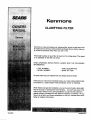
Kenmore
CLARIFYING FILTER
--
HOW TO INSTALL --
-- HOW IT WORKS m
-- CARE OF --- SPECIFICATIONS
--
PRINTED
IN U.S.A.
REPAIR PARTS-
--
I WARRANTY
I
SEARS
in accordance
or workmanship
RESIDENTIAL
with our instructions,
WATER
Sears will repair,
FILTER
free of charge,
I/I/
detects in material
in this water filter.
FULL
[_//
I/l)
FIVE YEAR
WARRANTY
AGAINST
LEAKS
_lll
I///
For five years from
model
the date of purchase,
Sears will furnish
water filter tank, free of charge, if the tank develops
TO OBTAIN WARRANTY
SERVICE, SIMPLY CONTACT
VICE CENTER THROUGHOUT
THE UNITED STATES.
while
this product
This warranty
vary from
state
is in use in the United
gives you specific
and install
a new current
a leak.
THE NEAREST
This warranty
I///
SEARS
applies
SERonly
States."
legal rights,
[_/I
_//1
I(((
))))
and you may have other rights which
to state,
[_/_
lit/
T///
Sears, Roebuck
and Co., Dept. 731-CR-W,
Sears Tower, Chicago,
IL 60684
If you want you r clarifying filter professional ly installed, talk to you r Sears Salesperson
a prompt, quality installation
by Sears Authorized
Installers.
SEARS INSTALLATION
POLICY
All installation
labor arranged by Sears shall be
performed
in a neat, workmanlike
manner in
accordance with generally accepted trade practices. Further, all installations
shall comply with
all local codes, regulations
and ordinances.
Customer shall also be protected, during installation, by insurance relating to Property Damage,
Workman's Compensation
and Public Liability.
SEARS INSTALLATION
t1/1
who will arrange
WARRANTY
In addition to any warranty extended to you on
the Sears merchandise involved, which warranty
becomes effective the date the merchandise
is
installed, should the workmanship of any Sears
arranged installation
prove faulty within one
year, Sears will, upon notice from you, cause
such faults to be corrected at no additional cost
to you.
I TABLE OF CONTENTS
PAGE
NO.
SECTION
SECTION
1
2
Safety Guides
..............................................
What Your Clarifying Filter Will Do ..............................
4
Water System Tests ..........................................
5
Where To Install The Filter ....................................
6
Planning Your Installation .....................................
SECTION
3
Step-by-Step
SECTION
4
Water Filter TimerlRecharge
SECTION
5
Timer Features ..............................................
Guides To Install .................................
How The Filter Works
SECTION
SECTION
6
7
4
Setup
.............................
6-8
9-14
15-16
16-17
........................................
Helpful Hints Checklist...Before
17
You Call For Service ...............
18
Keep The Filter Frorn Freezing .................................
19
Specifications/Dimensions
19
.....................................
Sweat Soldering Tips .........................................
SECTION 8
Repair Parts ................................................
2(_
21-23
I
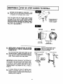
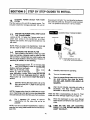
REMOVE PACKAGING
UNPACKING - Discard the carton, inserts,
foam pieces, and other packing items. DO
NOT throw away the small parts bag or the
transformer.
NOTE:
Check the filter (and carton) for shipping
damage, If you find damage, call your Sears
store for help.
SMALL PARTS BAG
(See page 9)
OWNERS MANUAL,
OTHER LITERATURE
TRANSFORMER
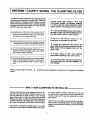
• Read all steps, guides and rules carefully before
installing and using your new water filter. Follow all
steps exactly to correctly install. Failure to follow
them could cause personal injury or property damage.
Reading this book will also help you to get all of the
benefits from your water filter.
PLEASE READ AND COMPLY WITH THE
FOLLOWING GUIDES TO PREVENT DAMAGE.
TO THE FILTER OR OTHER PROPERTY, PERSONAL INJURY, OR POSSIBLE FATAL SHOCK.
• THIS FILTER WORKS ON 24 VOLTS ONLY.
BE SURE TO USE THE TRANSFORMER INCLUDED, AND PLUG IT INTO A 120V OUTLET.
• Check with your local publicworks department for
plumbing and sanitation codes. You must follow
their guides as you install your filter.
•
Be sure
the
electric
outlet
for
the
transformer is grounded the right way.
•
Protect the filter and piping from freezing, see page I
19. Damage from freezing voidsthe filter warrant.
• Unplug the transformer right away if the
power cable should become damaged or frayed.
Make repairs before plugging back into the
power outlet.
• Use only LEAD-FREE SOLDER AND FLUX, as required by Federal and State codes, when installing soldered copper plumbing.
•
Always unplug the filter from electrical
power before removing outer valve covers.
• Your clarifying filter will clean yourwater as stated
below. It will not soften hard water or remove iron.
It will not purify polluted water or make it safe to
drink.
When you see this sign in the book, •
exactly.
• Connect the filter to the houee COLD water
(1200 max.) pipe only. DO NOT CONNECT TO
HOT WATER.
something could be damaged, or someone hurt, ifthe guide is not followed
WHAT YOUR CLARIFYING
A Sears Clarifying Filter takes sediments such as dirt,
sand, silt, clay, and fine organic matter out of water. You
can see sediments in water by filling a clear drinking
glass. When held up to light, you can see the particles
floating in the water, or settled to the bottomof the glass.
The filter is filled with "filter aggregate" mineral that traps
and holds the sediments as the water flows through it.
FILTER WILL DO
the water softener catches sediments that may get
through the filter. Sears Water Analysis Laboratory will
test your water and tell you what equipment you need
(see page 5).
NOTE: If you will install the clarifying filter along with a
Sears Solution Dispensing System, read the dispensing
system owners manual for treating a private well before
installing.
The Clarifier is sometimes installed alone, but is often
followedby a wamrsoftener. Besidessofteningthe water,
4
I SECTION
HELPFUL
21 BEFORE YOU START TO INSTALL
INFORMATION
If you know little about plumbing skills, we suggest
you get a book on the subject. There are many good
books for do-it-yourselfers on the basics of plumbing.
WATER SYSTEM TESTS
HAS YOUR WATER SUPPLY HAD A CHEMICAL
ANALYSIS? Sears has many kinds of water treating
units (see page 6) to correct different water problems.
To know the kind and size of unit you need, you must
first know what elements are in your house water
supply. A chemical analysis shows the type and
amounts of elements in water. If your water needs
analysis, call or write your nearest Sears store for
help.
CHECK YOUR WATER PRESSURE - For your filter
to work right, a water pressure of no lower than 20
pounds per square inch (psi) is needed in the house
water pipes. The highest pressure allowed in the
• water pipes is 125 psi. If pressure is over 125 psi, buy and
install a pressure reducing valve in the water inlet pipe
to the filter. NOTE: If water pressure during the day is 100
psi or more, pressure during the night may go over 125
psi.
If you have a well water system, look at the pressure
gauge to find the water pressure. Call your local water
department if you have city water. They will tell you
what the water pressure is where you live.
You can
Heating
soldered
on page
get a low cost book from Sears Plumbing and
departments that will help you. If you have
before, some basic sweat soldering tips are
20 of this manual.
CHECK YOUR WATER FLOW RATE - A water flow
of 51/2to 7 gallons per minute is needed. A lower flow
will keep your filter from working as well as it should.
To make an easy check of your flow rate, do the
following. You will need a 1 gallon container (can, jar,
pail, etc.).
1. Fully open 2 cold water faucets close to the point
water enters the house.
2. With both faucets open, fill the gallon container at
1 faucet while looking at a watch or clock to see
how many seconds it takes.
,
Empty the container and go to the second faucet
(be sure BOTH faucets are still on). Fill the gallon
container at the second faucet and see how many
seconds it takes.
4. Turn off both faucets. Now add the number of
seconds it took to fill the container at both faucets.
5. A total of 35 seconds, or less, means the system
flow rate is good.
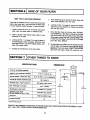
FACTS AND FIGURES TO KEEP
Fill in the blanks below and keep this book in a
safe place so you always have these facts.
Iron Content
Water Filter Model No. 1"
*pH
Serial Number 1
Water Pressure __
Date Installed
Water Flow Rate __
1"Get from the rating decal on the filter.
* The acidity or alkalinity measure of water.
Parts Per Million
__ Taste And/Or Odor __
Pounds/Square
Inch
Gallons Per Minute
I SECTION
I
21 BEFORE YOU START TO INSTALL
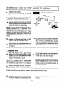
WHERE TO INSTALL THE FILTER
• • DO NOT install in a place where the filter could
freeze. Freeze damage voids the warranty by
Sears, Roebuck and Co. (See page 20).
Think of the following points as you choose a place to
put your filter (See FIG. 1).
Put the filter in a place water damage is least likely
to occur if it develops a leak. Sears or the manufacturer will not repair or pay for water damage,
• Place as close as possible to the pressure tank
(well water) or water meter (city water).
A 120V electric outlet, to plug the transformer into,
is needed within 10 feet of the filter (the filter has a
10 foot power cable). Be sure the outlet and transformer are in an inside place, to protect from wet
weather.
• Place as close as possible to a water drain such as
a. floor drain, laundry tub, sump or standpipe.
• • Connect to the house main water pipe BEFORE
THE WATER HEATER. Temperature of water going through the filter must not be more than 120°F
(49°C).
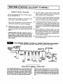
• Locate the filter in the water system as shown in
FIG. 1 below. For example, a taste and odor filter
always foltows a water softener, and the clarifying filter is installed ahead of other filters, and the
water softener.
When installing in an outside location, you must
take the steps necessary to assure the filter, installation plumbing, and wiring, are as well protected
from the elements, contamination, vandalism, etc.,
as when installed indoors.
Ae
Keep the filter out of direct sunlight. The sun's heat
can melt plastic parts.
THE PROPER ORDER TO INSTALL WATER TREATING EQUIPMENT
(Shows sequence of equipment only - seldom, if ever, would all items be needed)
.
._-. kitClmD
=
COLO
faucet
Sediment or "_--E_._.._q
Taste & Odor _
I
Cartridge
Filter
II
.
I+
_
k0t-sdt .-at. -,_
mid-aft .ter '_"
l_d _rattrtQ _-_
I r"--'-'--cltt mlw mlftt
utside faucetsl"l I
l--+
|"
F
.......
I
I Phosphate
I
I
It._ .
+aso
Feeder
water
J_.]
Taste &
Water
_oftener
I
/_1
Iron
-Filter Neutral-
Odor
Fitter
izing Fitter
Sed ment
_
(optional
\
location)
C • PPIr_:--
_R_er'e
b en
o, r:+ ngw+',,
t_l
water
^ _ ,.=_..,
__
_olunon
Dispensing System
PLAN HOW TO INSTALL YOUR FILTER
You must first decide how to run in and out pipes to the
filter. Look at your house main water pipe at the point
you will connect the filter. Is the pipe soldered copper,
glued plastic, or threaded galvanized or brass? What is
the pipe size? What kind of pipe and fittings is it easiest
for you to work with, and what tools do you have?
Now look at the common plans for in and out piping on
page 8. SeLectthe drawing best for you and use it as a
guide to plan what materials you will need, As you plan
your in and out piping, keep in mind the folk)wingcheck
list. Then get all the materials you will need before you
start.
6
I SECTION
TOOLS, PIPE, FITTINGS
AND OTHER MATERIALS YOU WILL NEED
OR THE FILTER WILL NOT BACKWASH RIGHT.
You can buy e 15 ft. hose from Sears, Item No.
42/65-3431.
In and out pipes to the filter must be at least 3/4 in.
size. Some local codes may tell you to use no less
than 1 in. pipe size.
Use copper, brass, or galvanized pipe and fittings. Some codes may also allow CPVC plastic
pipe.
t,_ Copper and galvanized pipe corrode fast when
connected together. Use pipe and fittings of the
same material.
v,'
I
2 I BEFORE YOU START TO INSTALL
NOTE: Flexible hose is not allowed by some codes.
If a rigid drain is required, buy an adaptor (garden
hose thread on 1 end) and plumb in following codes.
p,
TOOLS NEEDED - Common and cross point
(Phillips) screw drivers, slip-joint pliers and a tape
measure or rule. ALSO...
...for SOLDERED COPPER - tubing cutter, propane
torch, lead-free solder and flux, emery cloth, sandpaper or steel wool.
You can buy adaptors to go from a copper or
threaded main water pipe to CPVC in and out
•pipe.
...for THREADED PIPE - hacksaw or pipe cutter,
pipe wrenches, pipe threading tool, pipe joint compound approved for use on potable water.
Sears has kits and bypass valves you can buy to
help make installing your filter easier• See page 8.
...for CPVC PLASTIC - hacl_saw, adjustable
wrench, solvent cement approved for use on
potable water, primer.
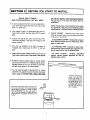
v" ALWAYS install a bypass valve or valves. Either
use 3 shut-off valves, or 1 of Sears special valves.
Bypass valves let you turn off water to the filter,
but still have water in the house pipes.
--..........____.
YOUR
HOUSE
MAIN
WATER
PIPE"
v," You will need a length of standard 5/8 in. inside
diameter (I.D.) garden hose for the filter drain (see
step 9, page 12). DO NOT USE A SMALLER HOSE
*IN WHAT DIRECTION
DOES
THE WATER
FLOW? BE SURE TO
PLAN IN AND OUT PIPING
SO WATER FLOW IS TO
THE FILTER INLET, PLAN
A CROSSOVER (FIG, 2
OR 3) IF FLOW IS FROM
LEFT TO RIGHT,
;=={,
DRAW THE PLANS FOR YOUR IN AND OUT PIPING HERE.
BE SURE
TO FOLLOW
GUIDES
LISTED ABOVE. INCLUDE
ALL PIPE, FITTINGS
AND ACCESSORIES
YOU WILL USE. MAKE A
1'20V
OUTLET
LIST OF ALL MATERIALS
YOU NEED AND BUY
THEM BEFORE
YOU BEGIN TO INSTALL THE
FILTER.
VALVE
INLET
I SECTION
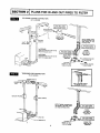
2 J PLANS FOR IN AND OUT PIPES TO FILTER
SOLDERED
I
COPPER CONNECTION
{_/, IN. SHOWN)
I
PUSH, IBD
NOT
INCLUDED
BUY FROM
FOR BYPASS
SEARS
_J_,_._
.
pus/.I
lOB
Bypass Valve
Sears Item No.
47./65-3436
IN_
S_R .A/_D
vtc_
NOTE: Flexible connectors am not allowed in all
areas, Check your local
plumbing codes,
OUTLET
VALVE
INLET
VALVE
NOTINCLUDED
BUY FROM SEARS
for SERVICE
Open the inlet and outlet valves
Close the bypass valve
tot BYPASS
Close the inlet and outlet valves
Open the bypass valve
OUT
Flexible
Connectors
Sears Item No.
42/65-3440
I BUY
NOT FROM
INCLUDED
SEARS
Bypass Vtdve
Sears Item No.
42/65-3437
I
PULL STEM OUTWARD
FOR SERVICE
connecL_
directly to valve
inlet and outlet
IN
PUSH STEMINWARD
FOR BYPASS
CROSS-OVER
THREADED
PIPE CONNECTION
(3/4IN. SHOWN)
BYPASS
VALVE
USE IF WATER SUPPLY
IS FROM "II"IE LEFT
F'-'-WATER
i
OUTLET
VALVE
C
I INLET VALVE
NOTE: Flexible connectors ere
not allowed in all areas. Check
your local plumbing codes.
NOT tNCLUOED
BUY FROM SEARS
Fh_xitde
Connectors
Sears Item No
42/65-3440
OUT
I
I
Union (2)
_J
_"
NOT FROM
INCLUDED
BUY
SEARS 7
Reducer (21
connects F
directly to valve
inlet and outlet
Bypass Valve
Sears Item No.
42/65-3437
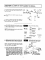
I SECTION
3 I STEP BY STEP GUIDES TO INSTALL
Close the shut-off valve on the house main water
• I.
pipe, near the water meter or pressure tank, to
turn off the water.
Shutoff
Shutofl
Valve
Pressure
Valve
Tank
Meter
Pump
I'
r-_. Shut off the gas or electric supply to the water
heater.
Electrical
Gas
Valve
Panel
• 3.
Open the highest and lowest water faucets in
your house to let water drain from the pipes.
Close faucets after water has drained.
4.
Take all the small parts from the parts bag and
lay out neatly where you can easily see and get
SMALL PARTS BAG ITEMS
to them as they are needud.
(_)
NOTE: The inlet screen is not used on the clarifying
filter, and can be discarded.
INLET
SCREEN
_'_
_
_NLET-OUTLET
ADAPTOR (2)
O
(-_ WASHER OR
_J GASKET (2)
_
I]
CLIP (2)
GROUND
CLAMP (2)
___________
|NLET.OUTLET
TUBE (2)
TRANSFORMER
_
® _
_INL_r-OUTLE¢
_
NUT (2)
GROUNDWIRE,
_, Q= SCREWS AND NUTS
5,
INSTALLING INLET AND OUTLET
ADAPTORS OR BYPASS VALVE
INSTALL INLET AND OUTLET ADAPTORS OR
SEARS BYPASS VALVE, ITEM NO. 42/65-3437.
Clips
(2)
NOTE: If you will install the bypass valve, the adaptors are not used. If you do not install the bypass
valve, you must use the adaptors.
am
INLET AND OUTLET ADAPTORS (Adaptors
and clips are small parts bag items.) - Push the
adaptors into the valve inlet and outlet ports
(FIG. 5 and 7) as far as they will go. Both adaptors are the same and fit either valve port. SNAP
THE 2 LARGE HOLDING CLIPS INTO PLACE,
FROM THE TOP DOWN AS SHOWN. BE SURE
THEY SNAP FIRMLY INTO PLACE, SO THE
ADAPTORS WILL NOT PULL OUT...GO
TO
STEP 6.
Adaptors
SEALS
PLACED tN
ONLY. CLIP SNAPS
INTO INNER GROOVES
(SEE FIG. 7)
9
//4
OR
P/
I SECTION
L
D.
3
I
STEP BY STEP GUIDES TO INSTALL
BYPASS VALVE ITEM NO. 42/65-3437 - If not
already done, put a light coating of silicone grease
or Vaseline on the bypass valve o-rings.
Push the bypass valve into the filter valve as far as
it will go (FIG. 5, 6 and 7). SNAP THE 2 LARGE
HOLDING CLIPS INTO PLACE, FROM THE TOP
DOWN AS SHOWN. BE SURE THEY SNAP FIRMLY
IN PLACE, SO THE BYPASS VALVE WILL NOT
PULL OUT. GO TO STEP 7.
IN
SIDE VIEW
TURN BYPASS VALVE
UPStDF.-DOWN TO
CONNECT TO FLOOR
LEVEL PLUMBING
END VIEW
/_-_CLIP
Valve Body
|ntet or Out_et
6,
a,
INSTALLING BYPASS VALVE
ITEM NO. 42/65-3436, OR
3-VALVE BYPASS
INSTALLING 3 VALVE BYPASS, OR SEARS
BYPASS VALVE, ITEM NO. 42/65 3436, AND
PIPES (FIG. 8).
SINGLE
Cut the house main water pipe where you wilt
connect the filter. Loosely put together pipe, fittings, and the 3 valves or Sears special bypass
valve. Place valve(s) within easy reach.
IMPORTANT: WHEN LOOKING AT THE FRONT OF
THE FILTER, THE INLET IS ON THE RIGHT SIDE.
IF WATER IN YOUR HOUSE MAIN WATER PIPE
RUNS FROM LEFT TO RIGHT, BE SU RE TO USE A
_CROSS-OVER"
AS SHOWN IN FIG. 2 AND 3,
PAGE 8.
b,
Of
Bypass Venire
(Push all the way in)
VALVE
BYPASS
3-VALVE
BYPASS
Filter
FiRer
inlet
If all pipe, fittings and valves fit together good,
tighten all threaded joints (use pipe dope on
outside threads), or solder atl joints following the
soldering tips on page 20.
10
I SECTION
7.
3 I STEP BY STEP GUIDES TO INSTALL
CONNECT THE FILTER
(Refer to your plan drawing on page 7, and to page
8.)
INLET-OUTLET
FITTINGS
Gasket
Tube
- SOLDER COPPER OR CPVC PIPE
a.
Read the important note in step 6. Then put the
gaskets, tubes and nuts shown in FIG. 9, or the
flexible connectors* (Sears kit, page 8) onto the
inlet-outlet adaptors or bypass valve.
Inlet an0 Outlet
Aclaptors
NOTE: The nuts, tubes and gaskets are for 3/4 in.
plumbing connection. For 1 in. connection, do not
use the nuts, tubes and gaskets. From your local
hardware store, buy 2 sweat adaptors (1 in. female
thread x 1 in. sweat) and plumb directly to the installation adaptors or bypass valve. Threads on the
installation adaptors and bypass valve are 1 in. pipe
thread.
b.
Measure, cut and put all pipe and fittings
together up to the main water pipe, or to the
bypass valve(s) you installed in step 6.
C.
When all piping fits together good, solder (or
solvent cement CPVC) all joints following tips
on page 20.
- THREADED
all
• CAUTION: BEFORE SOLDERING, DISCONNECT
NUTS (FIG. 9) ATTHE ADAPTORS OR BYPASS
VALVE. THIS WILL STOP THE HEAT, CAUSED
BY THE SOLDERING, FROM GOING INTO THE
FILTER VALVE AND MELTING PLASTIC PARTS.
After plumbing cools, put nuts back on and tighten.
PIPE
Read the important note in step 6. Then
measure, cut, thread and put together pipe and
fittings from the inlet-outlet adaptors (or bypass
valve) up to the main water pipe, or to the
bypass valves installed in step 6.
Cm
CAUTION: BE VERY CAREFUL WHEN Pu'r-FING
PIPE FITTINGS ONTO THE PLASTIC THREADS
OF THE INLET-OUTLET ADAPTORS, OR THE
BYPASS VALVE. DO NOT CROSS-THREAD. DO
NOT OVERTIGHTEN.
NOTE: For 1" connection, use a 1" fitting directly
on the installation adaptors or bypass valve. Threads
on the adaptors or bypass valve are 1 in. male pipe.
b.
Cut pipe lengths exact for correct aligning, and to
prevent stress on the filter valve. Use pipe dope
or teflon tape on all outside threads.
Include union fittings or flexible connectors*
(Sears kit, page 8).
*Flexible connectors are not allowed in all areas. Check your local plumbing codes.
8,
Fasten or support all piping (use pipe hangers)
to keep the weight of the plumbing off of the
filter inlet and outlet fittings, so they do not leak
or break.
11
I
I
i
Is oT,o.
3IsT P
BY
sT G
p u,oEs
TO,.S .L
CONNECT A VALVE DRAIN HOSE
9°
The valve drain fitting has standard garden
hose threads. Connect a 5/8" I.D. MINIMUM size
garden hose to it, Put the other end of the hose over
the floor drain (FIG. 10), or into a laundry tub, sump,
standpipe or other suitable drain. CHECK YOUR
LOCAL CODES.
IMPORTANT
dram
drain
NOTES:
Flexible drain hose is not allowed
NOTE ON PAGE 7.
,_
in all areas. SEE
Dram
Hose
_..
1_,'_'' Air Gap
• Leave an air gap of about 1-t/2" between the end of
the hose and the drain. This gap is needed so you
don't get a back-flow of sewer water into the filter. DO
NOT put the end of the hose down into the drain or
connect without an air gap.
Laumdry
• Place or support the hose so it does not kink or have
sharp bends. FASTEN THE END OF THE HOSE TO
A BRICK OR OTHER HEAVY OBJECT SO WATER
PRESSURE WILL NOT MAKE IT "WHIP."
--- - _
Keep the hose lower than the drain fitting. (In some
homes, to get to a drain you must raise the hose and
run it over-head. If you need an over-head drain, do
not raise the hose more than 8' above the floor or the
filter will not work as it should.
Tub
Floor Drain
_____ STANDPIPE
SUMP
1-1 2'
Support
manner
"-_-_
12.
_1
Standpipe
in some
at this point
I
IS C ,O.
3]sT p
BYs.E.GU,OES
,NSTA'L
10,
TESTING YOUR PLUMBING
WATER LEAKS.
WORK
FOR
Look at the picture in FIG. 11 showing your kind of
bypass valve(s). On a single valve, slide the stern into
SERVICE. On a 3-valve system, open the inlet and
outlet valves and close the bypass valve.
a.
OPEN A HOT AND COLD WATER FAUCET TO
LET AIR OUT OF THE FILTER AND HOUSE
PIPES.
b.
Fully open the shut-off valve in the house main
water pipe to turn on the water.
C.
d.
BYPASS VALVES
SINGLE
VALVE
PULLSTEM
OUTWARD
FOR
SERVICE
(brass)
Push
Inward
For
Bypass
PUSH
INWARD
FOR
SERVICE
Push
Inward
For
After water from the faucets runs smooth with no
more air bubbles, close them.
Check your plumbing work for leaks and fix right
away if any are found. READ THE CAUTION
NOTE AFTER STEP 7C (SOLDERED COPPER
OR CPVC PIPE), PAGE 11.
Ou.e_"" "_F_
11•
INSTALL GROUNDING WIRE BETWEEN
THE FILTER IN AND OUT PIPES
The house cold water pipe (iron or copper) is often
used to ground all electric outlets in the home. Outlets
are grounded to protect you from shock when you
touch any electric appliance plugged into the outlet. If
you didn't install a 3-valve bypass, or a brass single
bypass valve (FIG, 11), the cold water pipe ground is
broken.
_'_",,.
COLD WATER PIPE GROUND
Ground
Wire
Cramp (2)_
_
From
• To restore the ground, take the clamps (2), screws
(2), nuts (2) and ground wire that were in the small
parts bag. Install across the iron or copper in and out
pipes as shown in FIG. 12. Be sure good contact is
made between the pipe and the clamps. Fasten the
ground wire tightly between the clamps.
Valve
Outlet
WATER METER JUMPER
IMPORTANT: Be sure the cold water pipe has direct
metal to metal contact all the way to the ground.
Plastic, rubber or other electrically insulating parts
such as hoses, fittings, washers or gaskets can break
the direct metal to metal contact. Also check the
water meter (city water) or the well pump. Install #4
copper jumper wires, clamped tightly on both ends,
across insulated parts (FIG. 13).
Water
Meter
#4 Groundwire
13,
To
Valve
|nlet
WIRE
I SECTION
ELECTRIC
12. FILTER
I
3 I STEP BY STEP GUIDES TO INSTALL
POWER
OUTLET
FOR YOUR
house power to 24 volts.You must plug the transformer
into a 120 volt outlet only. Be sure the outlet is always
"live" so spmeone cannot turn it off by mistake.
The filter works on 24 volt, 60 Hz electric power. The
included transformer changes standard 120 volt AC
FASTEN THE POWER CABLE AND PLUG IN
CONNECTING
TRANSFORMER
i
-
13. THETRANSFORMER
Looking at FIG. 14, fasten the 2 power cable lugs (1
under each screw) to the transformer as shown.
Tighten both screws, then plug the transformer into
the outlet.
Transformer
NOTE: When you plug in the transformer, 12:00 AM
and SU begin to flash in the face plate display.
14.
SANITIZING THE WATER FILTER
Care is taken at the factory to keep your filter
clean and sanitary, Materials used to make the filter
will not infect or contaminate your water supply, and
will not cause bacteria to form and grow. However, if
sanitizing is needed, do the following.
Press and hold button [] on the face plate
a.
until RCHG be-_ginsto flash in the face plate
display, starting a backwash.
After 5 to 10 minutes, press
button [] again to start fast
rinse. Wait about 1 minute, THEN TURN OFF WATER
TO THE FILTER AT THE MAIN SUPPLY VALVE.
Press button [] once more to return the valve to
service.
bll
\_/
dll
e.
f.
gll
C.
Put 1 teaspoon (0.1 ounce) of calcium
hypochlorlte into the valve inlet as far as
possible.
15.
14.
Power
Cable
(Hook
either
lead
Carefully reconnect the plumbing.
Turn on the water supply.
Open the nearest filtered water faucet until you
can smell chlorine, then close the faucet.
DO NOT USE WATER FOR ABOUT 45
MINUTES.
After the 45 minutes, see step a to start a
backwash. The filter will complete this
backwash in about 35 minutes.
While the filter is backwashing, do step 15. Then
make the timer settings beginning on page 15.
ha
NOTE: You can buy calcium hypochlorite in tablet or
granular form using trade names such as Perchloren
and HTH.
_
r--
under either transformer terminaL)
Carefully remove the large plastic clip at the
filter valve inlet (FIG. 7, page 10) and pull the
adaptor out.
NOTE: If bypass valve, Item No. 42/65-3437 is installed, or if plumbing is too rigid to move, also disconnect
the outlet side and move the filter away from plumbing.
I
When the backwash is over, open filtered
water faucets until chlorine odor is gone, then
close.
TURN ON THE GAS (OR ELECTRIC)
SUPPLY TO THE WATER HEATER AND
LIGHT THE PILOT.
I SECTION
4 I WATER FILTER TIMER/RECHARGE
I
SETUP
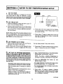
1• SET
THE TIMER
After the transformer
is plugged into the electricaL ouUet (step 13, page 14), 12:00 AM SUnday
began to flash in the time display, Set the time of day,
present day of week, days and/or time of recharge.
A. SET
display
/
buttons
TIME OF DAY
1. Press the PRESENT
TIME AND DAY button []
once. The hour display flashes.
2. Press the SET/CLEAR button [] until the present
hour of the day shows in the display. Be sure AM
for morning hours, or PM for afternoon and evening hours shows.
3. Press button [] once to steady the hour display,
and minutes begin to flash. Repeat step 2 to set
the correct minutes,
NOTE: Press button [] and quickly release to move
the hour display ahead I at a time to the correct hour.
Or, hold button [] to move the display ahead 2 hours
each second, to the correct hour.
B. SET
PRESENT
4. Press button [] again to steady the minute display (day will begin flashing). Figure 15 shows the
timer set at 3:30 PM.
DAY OF WEEK
1. Press the SET/CLEAR button [] to set the present day of the week in the display.
the day display ahead 2 days each second.
NOTE: Press button [] and quickly release to move
the day display 1 at a time. Or, hold button [] to move
2. Press button [] again to steady the entire display.
Figure 15 shows the timer set at TUesday.
C,
SET DAYS OF RECHARGE (BACKWASH)NOTE, IF YOU HAVE A WATER SOFTENER OR
OTHER AUTOMATIC FILTER: A good water flow rate
is needed for proper recharging and/or backwashing
of all water conditioners. To help assure good water
flow, you should offset the timers on each conditioner
so recharges do not occur on the same days, or at
the same time.
1. Read, "HOW OFTEN SHOULD YOU RECHARGE
(BACKWASH) THE FILTER", page 16.
NOTE: The timer is factory programmed to
recharge on Monday, Wednesday and Saturday.
2. Press the RECHARGE
SUnday begins to flash.
DAY
button
[]
and
...if you want recharges on Sunday (from table), press
the SET/CLEAR button [] to display ON.
...Most Sears water softeners are factory set (many
are adjustable) to recharge from 2:00 to 4:00 AM.
...If you do not want Sunday recharges, press button
[] to display OFF.
...Set the clarifying filter to recharge on different
days, or...
...Set the clarifying filter to recharge either 2 hours
before or after other equipment, or...
3. Press button
[]
again to display a flashing
MOnday. As you did in step 2 above, press button
[] to display ON for recharge on Monday, or OFF
for no recharge on Monday.
...Offset the timers on all equipment to beqin recharging at 12:00, 2:00 and 4:00 AM, or 1:00,
3:00 and 5:00 AM, etc.
continued
15.
I SECTION
4.
4 I WATER FILTER TIMER/RECHARGE
Press button [] for every day of the week, each
time using button [] to display ON (for recharge)
or OFF (no recharge) as needed.
D.
SET TIME OF RECHARGE (BACKWASH)
The filter is factory set to begin recharge at 2:00 AM,
ending at about 2:40 AM. If a different recharge time
is desired, or needed (see note under step C, page
15) do the following.
1.
SETUP
5.
After setting ON or OFF for Saturday, press button [] to return the present time in the display.
2.
Press the SET/CLEAR button [] until the desired
recharge starting time shows in the display.
NOTE: Press button [] and quickly release to move
the display ahead 1 hour at a time. Or, hold button
[] to move the display ahead 2 hours each second.
Press the RECHARGE TIME button [] once, to
display a flashing 2:00 AM, the factory setting.
3.
Press button
HOW OFTEN SHOULD YOU RECHARGE
(BACKWASH) THE FILTER?
[]
to return the present time.
RECHARGE (BACKWASH) GUIDE
WATER
The clarifier needs backwashing when you can see
sediments in the water, or when faucet water
pressure drops. When that happens depends on
how much sediment is in the water supply, and how
much water your household uses. You can use the
following table as a guide.
CONDITION
normal sediments,
dirt, etc.
normal sediments, dirt, etc.,
RECHARGES
PER WEEK
1
2-3
WITH iron
high sediments,
dirt, etc.
high sediments, dirt, etc.,
WITH iron
2
3-4
NOTE:Thetimerisfactoryprogrammedfor Monday,Wednesday and Saturdayrecharge.
I SECTION
5 I TIMER FEATURES
VACATION
The day you leave on vacation or other long absence,
press (DO NOT HOLD) the VACATION ON/OFF
button I-_. VAC begins to flash in the display. The
timer will keep time but the filter will not recharge
and waste water.
the filter will not recharge and you will soon have
sediments in your water supply.
NOTE: While in VACATION, the filter will go through a
recharge if the RECHARGE NOW feature (See below) is used.
When you return, press the VACATION button []
again to return the filter to service, and the correct
time of day in the display. Remember to do this or
NOTE: To shut off the water supply to the filter, use
the plumbing bypass valve(s)...
FIG. 11, page 13.
RECHARGE
For times you expect to use more water than usual,
use the RECHARGE NOW feature. Press the RECHARGE NOW-HOLD button [] and hold in for 3
NOW
seconds. RCHG begins to flash in the display and a
recharge starts right away. You will have filtered
water when the recharge is over in about 35 minutes.
16.
TIMER"POWER-OUTAGE
If e_ectrical power to the timer goes off, the "memory"
buitt into timer circuitry keeps all settings for 6 hours
(minimum) or more. The display is blank and the'filter
will not recharge. When electrical power comes on, 1
of 2 things will happen.
MEMORY"
2. The display will show a time, but it will be
flashing. The timer memory did not keep the
time settings and they must be reset (page 15),
The flashing display is to remind you to reset
the timer.
1. The present time of day will show, mean. ing the timer memory has kept all settings.
NOTES:
NOTE: tf the filter was in a recharge when power
was lost, it will now finish the cycle.
When power comes on, the flashing display returns to a time of 12:00 AM Sunday, then begins to
keep time again, if you do not reset all time settings, the filter will recharge 3 days each week.
However, recharges will most likely be on the
wrong days and at the wrong time.
If the filter was in a recharge when power went off,
the valve will return to service position without
finishing the recharge cycle.
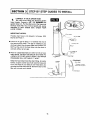
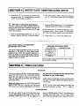
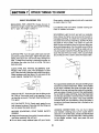
HOW YOUR CLARIFYING
FILTER WORKS
FILTERED
WATER OUT
The clarifying filter is filled with a mineral called "filter
aggregate." This mineral looks something like coame
sand. During service (FIG. 16) water goes into the filter
and DOWN through the bed of mineral. The mineral
takes the dirt, sand, silt, clay and other sediments out
of the water and holds it in the bed. Clear, clean water
goes out of the filter arid into the house pipes.
RECHARGE
WATER
IN
SERVICE
BYPASS
WATER OUT
Mir_rar
Bed
WATER
rN
BACKWASH
BACk'3NASH - After a time, the mineral needs cleaning to flush out all the sediments held by the mineral.
This cleaning is called backwash. In backwash, water
flows UP through the mineral. The dirt and other
sediments flush out of the mineral, out the top of the
filter, and to the drain. Backwash is about 25 minutes
long.
FAST RINSE - After backwash, the water flow changes
direction and goes downward through the filter at a
fast rate. Dirt and other sediments, left at the bottom
of the mineral bed, are flushed to the drain. The fast
rinse is about 5 minutes tong. Then, the filter returns
to service.
17.
"_25 minutes)
Mineral
Bed
FILTERED
WATER OUT
WATER
IN
. C;ain
FAST RINSE
(5 minutes)
I SECTION
6 I CARE OF YOUR FILTER
BEFORE
I
YOU CALL FOR SERVICE
HELPFUL HINTS CHECKLIST...TO
HELP YOU SAVE MONEY
By making a few easy checks, you can often avoid an unneeded service call. If your water filter fails to work,
check these things. If, after making the checks it still does not work right, call your Sears Service Department.
FILTER WILL NOT BACKWASH
(Water contains sediments, iron, dirt, sand, etc.)
HOUSE WATER PRESSURE LOW
_-]
MANUAL
INMove
BYPASS
POSITION BYPASS
- See FIG. VALVE(S)
11, page 13.
stem
in single bypass valve to SERVICE. In a
3-valve bypass, open the inlet and outlet valves, close
the bypass valve.
TRANSFORMER
THE
WALL
OUTLET, UNPLUGGED
OR POWER AT
CABLE
DISCONNECTED - Check for loss of power
and correct. Reset the times, then use the RECHARGE
NOW feature (See page 16).
r_
FUSE BLOWN, CIRCUIT BREAKER POPPED, OR CIRCUIT SWITCHED OFF - Replace
fuse, reset circuit breaker, or switch circuit on.
Reset times and use the RECHARGE NOW feature.
[]
MEMORY,"
TIMER
VACATION
(VAC)
POSITION
- Press IN
theTHE
VACATION
button
once
to return
the filter to service (page 16).
r-_
TIMER
NOT- SeePROGRAMMED
FOR
RECHARGES
pages 15 and 16 to select
and program a schedule. Use the RECHARGE
NOW feature.
[]
WELL PUMP PRESSURE SET TOO LOW Adjust to a MINIMUM of 20 psi.
I'_
BACKWASH
OFTEN - TO
KEEP FIL1;ER NEEDED
MINERAL MORE
BED CLEAN
Set
the timer for more recharges (See pages 15
and 16).
_'_
NOTE: SEE "TIMER POWER-OUTAGE
PAGE 17.
I_
VALVE DRAIN HOSE PLUGGED - Hose must
not have kinks, sharp bends, or any water flow
blockage. (See page 12.)
18.
I SECTION
6 I CARE OF YOUR FILTER
KEEP THE FILTER FROM FREEZING
If the filter is installed where it could freeze (summer
cabin, lake home, etc.), you must drain al! water from
it to stop possible freeze damage. To drain the filter 1.
Pull the holding clipto remove the drain fitting, with
drain hose attached, from the valve.
6.
Looking at FIG. 5 on page 9, remove tt_e plastic
clips and pull the adaptors or bypass valve from
the inlet and outlet.
Close the shut-off valve on the house main water
pipe, near the water meter or pressure tank.
.
2.
Open a faucet in the filtered water pipes to vent
pressure in the filter.
.
Looking at FIG. 11 on page 13, move the stem in
a single bypass valve to bypass. Close the inlet
and outlet valve in a 3-valve bypass system, and
open the bypass valve.
4.
.
and CAREFULLY (the filter is heavy) tip the filter
over so the valve inlet and outlet are over the drain.
Allow water to drain from tank. DO NOT REST THE
FILTER ON THE INLET AND OUTLET FITTINGS
OR THEY WILL BREAK.
.
Unplug the transformer at the wall outlet.
I SECTION
7
i
Move the filter close to the floor drain. SLOWLY
Tip the bottom of the filter up a few inches and hold
until all water has drained. Leave the filter laying
like this until you are ready to use it. Plug the inlet
end outlet with rags to keep dirt, bugs, etc. out.
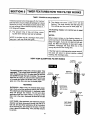
OTHER THINGS TO KNOW
SPECIFICATIONS
DIMENSIONS
DiA.
_1-
11,,-I1,,
[ (27.9 cm)
TYPE OF FILTERING MINERAL
II
Aggregate
AMOUNT OF FILTERING MINERAL
1.0 Cu. Ft. (.028 Cu M)
WATER PRESS. LIMITS (Min.-Max.)
20 to 125 PSI (1.4 to 8.4 Kg/Sq/Cm)
MAXIMUM WATER TEMPERATURE
120F (,_.9 C)
MINIMUM WELL PUMP CAPACITY
270 Gal/Hr (1022 Liter/Hr)
I
I rlteldDU1_t
Freeboard
18"(_
MIN, PIPE SIZE TO FILTER
3/4 In. (lgMM)
BACKWASH FLOW RATE*
4.5 Gal/Min(17 Uter/Min)
SERVICE FLOW RATE
(at max, pressure drop of 10 psi)
6.6 GaliMin(25 Liter/Min)
CAPACITY
MICRON RATING
(13g.s cm)
(124.5 ¢r_I
8600 Gal (32553 Liters)
25
"at 35 PSI inletpressure
i r
CAPACITY DETERMINED UNDER WQA STANDARD S-200 TEST CONDITIONS FOR FILTER GROUP IV, AND
MAY VARY WITH LOCAL WATER CHARACTERISTICS.
lg.
SECTION
7 I OTHER THINGS TO KNOW
SWEAT SOLDERING
TIPS
Wrap nearby, already soldered joints with a wet cloth
so solder does not melt.
MEASURING PIPE LENGTHS: Always be sure to
include the length of pipe that goes inside the fitting.
On 3/4"pipe, this length is about 3/4".
about
3/,-
:
engagement
NO
Let soldered joint_ cool slowly. Sudden cooling can
crack or weaken the solder.
SOLDERING: Light the torch and set to a moderate
flame. Move the flame over and around the joint to
heat pipe and fitting. In a short time, touch the end of
the solder wire to the tip of the fitting. DO NOT PLACE
SOLDER IN THE FLAME. The solder will melt and
draw into the connection when the pipe and fitting are
at the rig ht temperature. Run the solder around the lip
until the joint is full. Do not overfill as solder will run
into and harden inside the fitting. Being careful not to
touch the pipe with your hands, make a quick swipe
around the joint with a cloth to take off excess solder.
I
YES
_i i
CUTTING PIPE: Turn the pipe cutter back and forth
around the outside of the pipe. Tighten the pipe cutter
slowly with each turn until all the way through the
pipe. To keep from crushing or distorting the pipe, do
not tighten the cutter too much at a time. File burrs
from cut ends.
CLEAN PIPE AND FITTING SOLDERING
SURFACES: With emery cloth, fine sandpaper or steel
wool, clean the end of the pipe and inside of the fitting.
Clean surfaces until they shine. Do not grind off too
much material, making the fit too loose.
For a good sweat solder joint, the pipe and fitting must
not have any water inside them. Water, when heated
by the torch, weakens the solder and often the joint
will leak. If you can not keep the inside of the pipe dry,
wad up a piece of bread into a ball. After putting paste
flux on both the pipe and fitting, place the bread wad
into the pipe and poke in several inches. Put the pipe
and fitting together and solder. The bread absorbs
moisture while you are soldering. When the water is
turned on, the bread dissolves and is flushed out an
open faucet.
clean surfaces
thoroughly
CHECK THE FIT: Push the pipe into the fitting as far
as it will go. Use some force to slip together, but do
not hammer or pound. If too tight, clean surfaces until
fit is good.
PUT ON PASTE FLUX: Freely apply paste flux on
both cleaned surfaces. Place pipe into the fitting and
turn to spread the paste around.
BEFORE
GUIDES.
SOLDERING,
READ THESE
LEAKING CONNECTIONS:
You can try to reheat
and resolder a leaking joint, but it's usually best to
start over. Turn off the water, reheat and take the pipe
and fitting apart. Take off all old solder, cleaning down
to the copper surface. Apply new paste flux and
solder again.
SAFETY
• Keep torch flame away from walls, the water softener,
and other materials that will burn.
• Do not touch newly soldered
pipe with your hands.
20.
I SECTION
.._
12
11:"_$
_,_,,_,_
_'_E"
! _.'//:'__
_
._1
._"_'
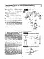
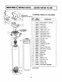
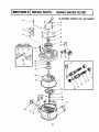
8 I REPAIR PARTS...
|_
_'_
SEARS WATER FILTER
VALVE COVER
,.,J SCREWS (2)...See page22
_ L_---_,,..
c...,F,..,.oo.. NO62S
3,8230
KEY
PART
NO.
NUMBER
1
7105047
BottomDistributor & Standpipe
18
2
7092202
Mineral Tank
19
3
7088855
Top Distributor
4
7096183
O-Ring,2-3/4 x 3
5
900039
O-Ring, 1-1/16x 1-1/14
6
7079092
O-Ring, 2-718x 3-1/4
7
7088033
ClampRetainer (2 req.)
8
7088041
Clamp Section(2 req.)
9
900300
Screw,#4.40 x 1/4 (2 req.)
10
7108304
Face Plate - Timer
11
708433O
Power Cord
12
7084306
Wire Harness
13
7095373
Transformer,24V-10VA
14
7090323
Top Cover
15
9OO562
Screw, #6 x 9/16 (4 req.)
116
VALVE ASSEMBLY
..,See page 22
•
21.
DESCRIPTION
16
9OO6O31 Screw, #8-18x 1/2 (2 red.)
17
7089047
Cover Bracket
18
900596
Speed Nut
19
7090315
BottomCover
2O
7092210 i Shroud
21
505647
Mineral, 1 cu. ft.
22
501783
Filter Sand, 10 Ibs.
23
501782
Gravel, 17 Ibs.
7097684
InstructionCard
7097668
OwnersManual(F642-2890)
Not illustrated
__
CLARIFIER,
3O
54
53
51
52
68
67
69
22.
MODEL NO. 625.348230
I SECTION
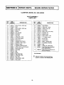
8 I REPAIR PARTS...
CLARIFIER,
MODEL
SEARS WATER FILTER
NO. 625.348230
VALVE ASSEMBLY
PARTS LIST
KEY
NO.
PART
NUMBER
3O
31
900120
7070462
900857
32
33
34
35
36
37
38
39
40
41
42
43
44
45
46
47
48
49
50
51
52
53
54
7064974
503288
7066439
"7080653
509537
900041
7077927
1205500
507369
507615
900570
507371
900535
900568
7082053
7081764
1219600
7092642
7092634
7081756
9001006
7103964
KEY
NO.
PART
NUMBER
Screw, #6.18x 3/8 (2 req.)
Motor
55
56
7082087
7064372
Screw,#6-20 x 3/6 (2 req.)
MotorPlate
Bearing
Cam and Gear
57
58
59
60
7064380
7085263
7074123
7077472
Clip (Drain)
FlowPlug
O-Ring, 5/8 x 13/16
Drain Hose Adaptor
61
62
63
64
7030713
7070412
900373
120375
Clip (2 req.) *
InstallationNut (2 req.) *
InstallationTube (2 req.),
Washer (2 req.),
Installation Adaptor (2 req.)*
65
66
67
68
69
500726
160505
7081201
7100940
900064
•
4920901
DESCRIPTION
O-Ring, 15/16 x 1-3/16(2 req.)*
Screen(inlet)* []
Valve Body
Seal
7092163
Spring
Plug (Drain Seal)
DESCRIPTION
Wave Washer
O-Ring, 3/4 x 15116
O-Ring, 7/16 x 5/8
Valve Cover
Screw, #10-14x 2 (5 req.)
ExpansionPin
Switch(2 req.)
Screw, #4-24 x 1-118
"C" Clamp(2 req.)e
Nut (2 req.)*
GroundWire-,
Screw, 1/4-20(2 req.)*
Clip (Nozzle & Venturi)
Plug
O-Ring, 1/4 x 3/8 (2 req.)
Small Parts Bag (Includes all
items marked with *)
Seal Kit (Incl. Key Nos. 48, 51,
52, 53, 56 and 57)
• Not illustrated
O-Ring, 3/8 x 9/16
Rotor Seal
[]
O-Ring, 3-3/8 x 3-5/8
Rotor & Disc
23.
Although included in the small parts bag,
screen is not used on the Clarifying Fitter.
Kenmore
CLARIFYING
FILTER
Now that you have purchased your clarifying filter, should a need ever exist
for repair parts or service, simply contact any Sears Service Center. Be sure
to provide all pertinent facts when you call or visit.
The model number of your filter is found on the rating decal. This decal
is on backside of the filter top cover.
WHEN ORDERING
INFORMATION:
REPAIR PARTS, ALWAYS GIVE THE FOLLOWING
- PART NUMBER
- MODEL NUMBER
- PART DESCRIPTION
- NAME OF ITEM
All parts listed may be ordered from any Sears Service Center.
If the parts you need are not stocked locally, your order will be electronically
transmitted to a Sears Repair Parts Distribution center for handling.
When Sears arranges the installation, you can be sure the job is done right.
We will arrange for professional workmanship...and
we'll take care of the
entire project. What's more, during installation you get insured protection...
against property damage and also against accidents to workmen. All you
have to do is talk to your Sears salesperson or call your nearest Sears store
today for detailed information.
F642-2890
7097668 (3/91)