1
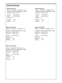
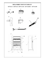
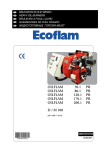
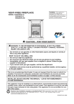
Installation Instructions and Homeowner’s Manual
WARNING! IF THE INFORMATION IN THIS MANUAL IS NOT FOLLOWED EXACTLY, A FIRE MAY RESULT
CAUSING PROPERTY DAMAGE, PERSONAL INJURY OR LOSS OF LIFE.
FOR YOUR SAFETY
DO NOT STORE
OR USE GASOLINE OR OTHER
FLAMMABLE VAPORS OR LIQUIDS
IN THE VICINITY OF THIS OR ANY
OTHER APPLIANCE
INSTALLER: DO NOT DISCARD THIS MANUAL-LEAVE FOR HOME OWNER
1
PC(220)-VCL100-01-0709
PLEASE READ THE INSTALLATION & OPERATION INSTRUCTIONS BEFORE
USING THIS APPLIANCE
IMPORTANT: Read all instructions and warnings carefully before starting installation. Failure to follow these
instructions may result in a possible electric shock, fire hazard and will void the warranty.
Important instructions ……………………………………………………………3
General…………………………………………………………………………….…3
Locating Your Electric Fireplace…………………………………… …………… 3
Clearance To Combustibles………………………………………… …………... 4
Electrical Connections…..……………………………………………… ………. 4
Electrical Specifications………………………………………… ……………..… 4
Service Instructions…………………………………………………………… … 4
Replacing Light Bulbs…………………………………… …………………………4
Glass Information……………………………………………… ………………… 5
Maintenance of Motors………………………………………… …………… … 5
Electrical Wiring Diagram……………………………………… ………………… 5
Operating Instructions…………………………………………………………… 6
On/Off Switch……………………………………………………………………. .. 6
Heater Control…………………………………………………………………… .. 6
Instructions for power………………………………………………………………. 6
Specifications………………………………………………………………….. …. 7
Replacement Parts Pictures…………………………………………………….. 8
Replacement Parts List (V50TYLA-O)…………………………………………… 9
Replacement Parts List (V50TYLA-C)……………………………………………10
Replacement Parts List (V50TYLA-DO)………………………………………… 11
Replacement Parts List (V50TYLA-BC)………………………………………… 12
Replacement Parts List (V50TYLAR-BC)……………………………………… 13
2
GENERAL
1.
2.
3.
Read all instructions before using this
13. Do not insert or allow foreign objects to enter any
appliance.
ventilation or exhaust opening as this may cause
This appliance is hot when in use. To avoid
electric shock, fire or damage to the appliance.
burns, do not let bare skin touch hot surfaces.
14. To prevent fire, do not block air intakes or exhaust
Keep combustible materials, such as furniture,
in any manner. Do not use on soft surfaces, such
pillows, bedding, papers, clothes, and curtains
as a bed, where openings may become blocked.
at least 3 feet(1m.) from the front of this
15. This appliance has hot and arcing or sparking parts
appliance.
inside. Do not use it in areas where gasoline, paint,
CAUTION: Extreme caution is necessary when
or flammable liquids are used or stored. This elec-
any heater is used by or near children or inva-
tric fireplace should not be used as a drying rack
lids and whenever the heater is left Operating
for clothing, Also, do not have Christmas stock-
and unattended.
ings or decorations hung on or near it.
16. Use this appliance only as described in this
4.
Always unplug heater when not in use.
5.
Do not operate any heater with a damaged
manual. All other uses not recommended by the
cord or plug or after the heater malfunctions,
manufacturer may cause fire, electric shock, or
has been dropped or damaged in any manner.
injury.
6.
7.
Any repairs to this appliance should be carried
17. Avoid the use of an extension cord because it may
out by a qualified service person.
overheat and cause a fire hazard. However if you
Under no circumstances should this electric fire-
must use an extension cord, the cord shall be
place be modified. Parts having to be removed
1.0 mm2 ,1900 Watts. The extension cord must
for servicing must be replaced prior to operat-
be a three wire cord with grounding type plug
ing this electric fireplace again.
and cord connector.
8.
Do not use outdoors.
9.
This heater is not intended for use in bathrooms,
18. SAVE THESE INSTRUCTIONS.
laundry areas or similar indoor locations. Never
LOCATING YOUR ELECTRIC FIREPLACE
use this appliance near a bathtub or other wa-
Your new freestanding electric fireplace may be
ter container.
installed virtually anywhere in your home.
10. Do not run cord under carpeting. Do not cover
However when choosing a location for your
cord with throw rugs, runners or the like. Arrange
new electric fireplace, ensure that the general
cord away from traffic areas and where it will not
instructions are followed. For best effect results, install
be tripped over.
the electric fireplace out of direct sunlight.
11. To disconnect this appliance, turn controls to
the off position and remove plug from outlet.
12. Connect to properly grounded outlets only.
3
CLEARANCE TO COMBUSTIBLES
WARNING: Electrical outlet wiring
must comply with local building
codes and all other applicable
regulations to reduce the risk of
fire, electrical shock and injury.
Back…………………………0mm
Sides……………..…………0mm
Floor……………. .…………0mm
WARNING: Do not use this
fireplace if any part of it has been
under water. Immediately call a
qualified service technician to
inspect the fireplace and replace
any part of the electrical system if
necessary.
Top………………. .…………610mm
ELECTRICAL CONNECTION
A 10 AMP, 220 Volt,50Hz circuit with a properly
grounded outlet is required. Preferably, the stove will
be on a dedicated circuit. Other appliances on the
same circuit may cause the circuit breaker to trip or
the fuse to blow when the heater is on operation.
The unit comes standard with a 6’ (1828mm) long
three wire cord exiting from the rear of the fireplace.
Plan the installation to avoid the use of an extension
cord. If an extention cord must be used, it must be a
minumum 1.0 mm2 three wire with grounding type
plug connector and rated no less than 1900 Watts.
ELECTRICAL SPECIFICATIONS
Voltage………………220 VAC/50Hz
Total Amps…………..6.5 Amps
Total Watts…………..1350 Watts
Heater Ratings………1200 Watts
SERVICE INSTRUCTIONS
WARNING: Disconnect power before
7.
attempting any maintenance or cleaning
to reduce the risk of fire, electrical shock
or personal injury
8.
9.
REPLACING LIGHT BULBS
This fireplace uses two clear 220 Volt, 60 Watt, E-14 socket
base light bulbs (small base, chandelier candle type).The
60 Watt bulbs are located under the log set/ember bed. For
convenience, if one of the bulbs burns out, it may be a good
Install the new light bulb(s) by holding the socket
and screwing them.
Reinstall the log set and screen. Follow the above
procedure in reverse order.
The diameter of the pilot light bulb is 5mm. If the pilot
light bulb need to be replaced, follow steps 1,2,3,4
above. Then use the pilot light bulb socket w/wiring
assembly replace the primary pilot part, and connect
wires according to primary connection . Then follow
step 8 above.
idea to replace both of the light bulbs.
1.
WARNING: Do not exceed 60
Turn off power to the unit by unplugging the power cord.
2.
Let fireplace cool if it has been operating.
Watts per bulb. Use of higher
3.
Remove the two fixing self-tapping screws on the screen.
rated bulbs may result in a fire
Pull the screen upward a little bit, and then out.
causing property damage and
4.
Remove the two screws that secure the log set in position.
personal injury.
5.
Examine the bulbs to determine which bulbs need to be
replaced.
6.
While holding the socket, unscrew the defective bulb (s).
4
GLASS INFORMATION
MAINTENANCE OF MOTORS
The motors used on the fan and flame genera-
1. Under no circumstances should this product
tor assembly are prelubricated for extended
be operated with missing or broken glass.
bearing life and require no further lubrication.
2. Do not strike or slam the glass.
3. Do not use abrasive cleaners to clean the glass.
However, periodic cleaning/vacuuming of the
fan/heater unit is recommended.
WARNING: Make sure that the
4.
Replacement glass is available from the manu
facturer and replacement should be carried out
power is turned off before
by a qualified service person.
proceeding.
ELECTRICAL WIRING DIAGRAM
Any electrical repairs or rewiring of this unit should be carried out by a licensed electrician in accordance
with national and local codes.
If repairing or replacing any electrical component or wiring, the original wire
routing, color coding and securing location must be followed.
5
Operating Instructions
This section provides easy step by step instructions for operating your fireplace.
1. Make sure the unit is unplugged from the power source。
2. Plug the fireplace into a 10AMP/220V outlet. If the cord does not reach, you may use an
extension cord rated for a minimum of 1900 watts.
To access the controls, open the bottom of the fireplace at the front of the unit (see Figure A).
A. MAIN ON/OFF SWITCH
The on/off switch supplies power to all fireplace functions (heater/flame).
B. HEATER THERMOSTAT CONTROL
To adjust the temperature to your needs, turn the thermostat control completely clockwise to turn on
the heater. When the room reaches the desired temperature, turn the thermostat knob counter
clockwise until you hear a click. Leave it in this position to maintain the room temperature at this
setting. For additional heat, turn clockwise until you hear the click again and the heater will turn on.
To turn the heater off, switch the HEATER ON/OFF SWITCH to the OFF position.
C. HEATER ON/OFF SWITCH
The HEATER ON/OFF SWITCH supplies power to the heater fan and the heater element.
NOTE: When switched ON, the heater fan will operate. The heater element may or may not be
on, depending on the thermostat control setting (see “HEATER THERMOSTAT CONTROL”).
When the HEATER/FAN pilot light is lighting, it indicate that the heater is on.
Warning: During any service of this appliance, the power to the unit must be turned off. It is
not acceptable to use the “ON/OFF” switch to meet this requirement. (Refer to operating
instruction section)
D. INSTRUCTIONS FOR POWER
This heater is for use on 220 volts only. The green/yellow grounding lug extending from the adapter
must be connected to a permanent ground such as a properly grounded outlet box. The adapter
should not be used if a three-slot grounded receptacle is available.
6
SPECIFICATIONS:
Model: V50TYLA-C
Voltage: 220V/50HZ
Model: V50TYLA-O
Total Amps: 6.5A
Voltage: 220V/50HZ
Total Amps: 6.5A
Total Watts: 1350W Heating Ratings: 1200W
Total Watts: 1350W Heating Ratings: 1200W
Dimensions, CM (H x W X D)
Dimensions, CM (H x W X D)
Fireplace
Fireplace
97.8x67x35.9
Carton
105.1x74.5x44.1
97.8x67x35.9
Carton
Weight, Kgs
105.1x74.5x44.1
Weight, Kgs
Fireplace
35.9
Fireplace
35.9
Shipping
43.1
Shipping
43.1
Model: V50TYLA-DO
Voltage: 220V/50HZ
Model: V50TYLA-BC
Total Amps: 6.5A
Voltage: 220V/50HZ
Total Amps: 6.5A
Total Watts: 1350W Heating Ratings: 1200W
Total Watts: 1350W Heating Ratings: 1200W
Dimensions, CM(H x W X D)
Dimensions, CM (H x W X D)
Fireplace
Fireplace
Carton
97.8x67x35.9
105.1x74.5x44.1
Carton
Weight, Kgs
97.8x67x35.9
105.1x74.5x44.1
Weight, Kgs
Fireplace
35.9
Fireplace
35.9
Shipping
43.1
Shipping
43.1
Model: V50TYLAR-BC
Voltage: 220V/50HZ
Total Amps: 6.5A
Total Watts: 1350W Heating Ratings: 1200W
Dimensions, CM (H x W X D)
Fireplace
Carton
97.8x67x35.9
105.1x74.5x44.1
Weight, Kgs
Fireplace
35.9
Shipping
43.1
7
REPLACEMENT PARTS PICTURES OF
V50TYLA-O V50TYLA-C V50TYLA-DO V50TYLAR-BC
2
9
6
V50TYLA-BC
7
5
4
8
V50TYLA-O
Ite m #
P a rt
1
Log
2
Fan/Heater A s s em bly
NFHTX186-R/V B 17-000-R
3
S y nc hroniz ation M otor-220V olt A C w/Term inal
FE 23A 307
4
Cord P ower H05V V -F3GX1.0 w/Term inal
NFHL008-R-A
5
ON/OFF S witc h
V L067-01
6
Heater Control (Therm os tat)
V L053-02
7
Heater Control K nob
NFHL012
8
Flam e Generator A s s em bly /Firewood Glis ten P aper P T/32GS 370/FE 33A 205-01
9
Light B ulb S oc k et w/W iring A s s em bly
P E 28A 306-R
10
S c reen
E B 29600
11
Top
E L040-01-O
12
S ide P anel (Right/Left)
13
De scripition
P a rt Num be r
S et
V L050-01A
P anel
E L015-06-O
Lower P anel
E L012-06
14
Door
E L013-01
15
B ras s K nob
224A
16
B ac k P anel
E L019-01-B
17
B as e
E L018-06RA -O
18
Upper Dec orating Fram e
E L016-06H-O
19
Upper Dec orating W ire
E L011-01
20
Upper (M id) Louver
V L015-01(V L014-01)
21
P ilot Light B ulb S oc k et w/W iring A s s em bly
V L080-01
22
B as e P late ( Not s hown)
V L091-01-R
23
Driverwheel 2(Not s hown)
V L005-03A
24
S witc h M ount P anel ( Not s hown)
V L004-01F
9
V50TYLA-C
Item#
Part Descripition
Part Number
1
Log Set
VL050-01A
2
Fan/Heater Assembly
NFHTX186-R/VB17-000-R
3
Synchronization Motor-220Volt AC w/Terminal
FE23A307
4
Cord Power H05VV-F3GX1.0 w/Terminal
NFHL008-R-A
5
ON/OFF Switch
VL067-01
6
Heater Control (Thermostat)
VL053-02
7
Heater Control Knob
NFHL012
8
Flame Generator Assembly/Firewood Glisten Paper PT/32GS370/FE33A205-01
9
Light Bulb Socket w/Wiring Assembly
PE28A306-R
10
Screen
EB29600
11
Top Panel
EL040-01-C
12
Side Panel (Right/Left)
EL015-06-C
13
Left Lower Panel/Right Lower Panel
EL012-06
14
Door
EL013-01
15
Brass Knob
224A
16
Back Panel
EL019-01-B
17
Base
EL018-06RA-C
18
Upper Decorating Frame
EL016-06B-C
19
Upper Decorating Wire
EL011-01
20
Upper (Mid) Louver
VL015-01(EL014-01)
21
Pilot Light Bulb Socket w/Wiring Assembly
VL080-01
22
Base Plate ( Not shown)
VL091-01-R
23
Driver Wheel 1/ Driverwheel 2(Not shown)
VL005-03A
24
Switch Mount Panel ( Not shown)
VL004-01F
1
100
V50TYLA-DO
Item# Part Descripition
Part Number
1
Log Set
VL050-01A
2
Fan/Heater Assembly
NFHTX186-R/VB17-000-R
3
Synchronization Motor-220Volt AC w/Terminal
FE23A307
4
Cord Power H05VV-F3GX1.0 w/Terminal
NFHL008-R-A
5
ON/OFF Switch
VL067-01
6
Heater Control (Thermostat)
VL053-02
7
Heater Control Knob
NFHL012
8
Flame Generator Assembly/Firewood Glisten Paper
PT/32GS370/FE33A205-01
9
Light Bulb Socket w/Wiring Assembly
PE28A306-R
10
Screen
EB29600
11
Top Panel
EL040-01-DO
12
Side Panel (Right/Left)
EL015-06-DO
13
Left Lower Panel/Right Lower Panel
EL012-06
14
Door
EL013-01
15
Brass Knob
224A
16
Back Panel
EL019-01-B
17
Base
EL018-06RA-DO
18
Upper Decorating Frame
EL016-06H-O
19
Upper Decorating Wire
EL011-01
20
Upper (Mid) Louver
VL015-01(VL014-01)
21
Pilot Light Bulb Socket w/Wiring Assembly
VL080-01
22
Base Plate ( Not shown)
VL091-01-R
23
Driver Wheel 1/ Driverwheel 2(Not shown)
VL005-03A
24
Switch Mount Panel ( Not shown)
VL004-01F
1 1
11
V50TYLA-BC
Item#
Part Descripition
Part Number
1
Log Set
VL050-01A
2
Fan/Heater Assembly
NFHTX186-R/VB17-000-R
3
Synchronization Motor-220Volt AC w/Terminal
FE23A307
4
Cord Power H05VV-F3GX1.0 w/Terminal
NFHL008-R-A
5
ON/OFF Switch
VL067-01
6
Heater Control (Thermostat)
VL053-02
7
Heater Control Knob
NFHL012
8
Flame Generator Assembly/Firewood Glisten Paper PT/32GS370/FE33A205-01
9
Light Bulb Socket w/W iring Assembly
PE28A306-R
10
Screen
EB29600
11
Top Panel
EL040-01-BC
12
Side Panel (Right/Left)
EL015-06-BC
13
Lower Panel
EL012-06
14
Door
EL013-01
15
Brass Knob
224A
16
Back Panel
EL019-01-B
17
Base
EL018-06RA-BC
18
Upper Decorating Frame
EL016-06H-BC
19
Upper Decorating W ire
EL011-01
20
Upper (Mid) Louver
VL015(VL014-01)
21
Pilot Light Bulb Socket w/W iring Assembly
VL080-01
22
Base Plate ( Not shown)
VL091-01-R
23
24
Driverwheel 2(Not shown)
VL005-03A
Switch Mount Panel ( Not shown)
VL004-01F
1
122
V50TYLAR-BC
Item#
Part Descripition
Part Number
1
Log Set
VL050-01A
2
Fan/Heater Assembly
NFHTX186-R/VB17-000-R
3
Synchronization Motor-220Volt AC w/Terminal
FE23A307
4
Cord Power H05VV-F3GX1.0 w/Terminal
NFHL008-R-A
5
ON/OFF Switch
VL067-01
6
Heater Control (Thermostat)
VL053-02
7
Heater Control Knob
NFHL012
8
Flame Generator Assembly/Firewood Glisten Paper PT/32GS370/FE33A205-01
9
Light Bulb Socket w/Wiring Assembly
PE28A306-R
10
Screen
EB29600
11
Top Panel
EL018-06RA-C
12
Side Panel (Right/Left)
EL015-06A(B)H-C
13
Left Lower Panel/Right Lower Panel
EL012-06
14
Door
EL013-01
15
Brass Knob
224A
16
Back Panel
EL019-01-B
17
Base
EL018-06RA-C
18
Upper Decorating Frame
EL016-06B-C
19
Upper Decorating Wire
EL011-01
20
Upper (Mid) Louver
VL015-01(EL014-01)
21
Pilot Light Bulb Socket w/Wiring Assembly
VL080-01
22
Base Plate ( Not shown)
VL091-01-R
23
Driver Wheel 1/ Driverwheel 2(Not shown)
VL005-03A
24
Switch Mount Panel ( Not shown)
VL004-01F
13