1
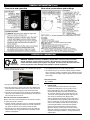
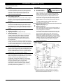
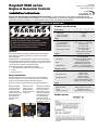
Keystart 9620 series
00-02-0657
nd
revision A, 22 September 2008
catalogue section 40 & 75
Engine & Generator Controls
Installation Instructions
Please read the following information before installing. A visual inspection of this product for damage during
shipping is recommended before installation. It is your responsibility to ensure that qualified mechanical and electrical
technicians install this product. If in doubt, please contact your local Murphy representative.
GENERAL INFORMATION
WARNING
BEFORE BEGINNING INSTALLATION OF THIS PRODUCT
Disconnect all electrical power to the machine
Make sure the machine cannot operate during installation
Follow all safety warnings of the machine manufacturer
Read and follow all installation instructions
Product specifications
power supply:
operating voltage:
steady state
brown out / cranking
current consumption
inputs:
fault switch inputs:
–ve input defined as:
speed sensing input:
generator AC (J2+J3 on)
The Keystart 9620 series provides manual start/stop and automatic
fault shutdown protection for generators, pumps and other enginedriven applications.
outputs:
run, preheat
Keystart features a 3 way keyswitch for operator control of the engine,
with 6 LEDs for indication of status and faults - see ‘front view’ diagram
for details. Electrical connection and configuration options are at the rear
- see ‘Rear view, connection and settings’ diagram.
start (crank)
For each Keystart ordered, the following is supplied:
• 1 x Keystart module, fitted with 2 x panel mounting clips
• 2 x keys
• these instructions
calibration/tacho
Panel installation
Secure the case to the panel with the two ratcheted mounting clips:
2.
At the front of the
panel, insert the
Keystart (without
clips) into the panel
cut-out (C).
alarm
(all ratings non-reactive)
positive DC, switched NO relay contact,
10 A max. @ 24VDC
positive DC via keyswitch contacts,
10 A max. @ 24V DC
negative DC (open collector
NPN transistor), 250mA max.
to suit 0 – 1 mA, 75 Ohm meter
output = 0.75mA at rated engine speed
adjustable settings:
preheat timer
fault override timer
Keystart is designed for front-of-panel mounting in a DIN standard
92 x 92 mm (3.6 x 3.6 in.) cut-out. Allow 75mm (3.0 in.) behind the
panel for the case depth, keyswitch and cable connection.
Remove the plastic
mounting clips from
the Keystart case:
release each clip’s
ratchet mechanism by
pulling outwards (A),
then slide the clip
back and off the
case (B).
close to negative DC during fault
–1V to +1V w.r.t. – ve DC supply
(model 9621 only)
70 – 270 VAC rms,
<50 to >60 Hz. nominal
10 – 60 VAC peak,
<2000 to >6500 Hz. nominal
mag. pickup (J2+J3 off)
General
1.
7 – 30 VDC
5 VDC
< 100mA
3.
At the rear of the panel,
refit the two mounting
clips into the slots on
the Keystart case (D).
Slide each clip forward
until the arms (E) are
secured behind the
panel face. Ratchet
mechanism (F) prevents
the clip from moving
backwards.
overspeed trip level
general:
overall dimensions (w x h x d)
panel cut-out size
weight
operating temperature
Model options
0 or 10 secs (link J1),
default = 0 secs
2 to 20 secs (VR1),
default = 10 secs
100 to 130 % (VR3) of
nominal speed calibration (VR2),
default = 110% (of 50 or 60 Hz)
96 x 96 x 95 mm / 3.8 x 3.8 x 3.7 in.
DIN 92 x 92 mm / 3.6 x 3.6 in.
approx. 300 g / 0.7 lb
–35°C to +55°C / –31°F to 131°F
GENERAL INFORMATION (cont.)
Front view and operation
Rear view, connections and settings
ELECTRICAL CONNECTION
DANGER !
HIGH VOLTS
WARNING: DANGER OF INJURY OR DEATH. Keystart 9621 controllers allow connection
of high voltage AC circuits. Before connection, disconnection or handling of these units,
ensure that all AC and DC power supplies are isolated. Connection to or disconnection from
live wiring may also cause damage to the Keystart’s internal components.
Electrical connection to 0.5 to 1.5 mm² / 16 – 20 AWG panel wiring is
by spring-clamp terminals at the rear.
• use separate routing for AC and DC wiring harnesses.
• use separate wiring for a) connection of battery charger to battery,
and b) connection of battery to panel DC supply. Separate wiring will
reduce high frequency battery charger output noise on the panel DC
power supply.
Terminal functions
Pin Function
• pre-strip 8 to 10 mm / 0.3 to 0.4 in. of insulation from each wire.
• Above each terminal is a square push-button with a diagonal slot.
Insert a flat-head screwdriver into the slot (A), then push down to
(towards the front of the Keystart) to open the terminal clamp.
• insert the wire into the terminal (B), checking that the insulation is
clear of the clamp. Release the screwdriver/spring clamp pressure
and check that the wire is secure.
General connection recommendations
Murphy make several recommendations for the electrical connection
of engine and generator controllers.
• minimise controller output load current (i.e. wear/tear and potential
damage) by using slave relays between the controller outputs and
high power end-devices such as fuel and starter solenoids.
• Suppress (at source) electrical interference from panel relay and
engine solenoid coils, using flywheel diode or proprietary snubber
networks as appropriate.
Murphy - Keystart 9620 series installation instructions
1
2
Run (fuel) output
Preheat output
These relay outputs provide control for a the engine’s
preheater and (energised to run) fuel / ignition circuits.
When configuration link J3 is on (the default setting),
the Preheat output (terminal 2) does not operate. If link
J3 is removed, terminal 2 gives a positive DC output for
10 seconds, and the preheat LED lights, beginning from
when the key is switched to the I (RUN) position.
After any preheat time has expired, the Run output (pin 1)
gives a positive DC output (operating engine fuel) and the
green ‘run’ LED lights. The Run output and LED remain
active until the operator switches the key to O (STOP) or
until the Keystart initiates an automatic fault shutdown.
Both Run and Preheat outputs are rated 10 Amp max.
@ 24VDC. Murphy recommend the connection of slave
relays with suppressed coils between these outputs and fuel
solenoid coil and engine preheaters - see ‘typical connection’
diagram below.
nd
00-02-0657 revision A 22 September 2008 p2/4
ELECTRICAL CONNECTION (cont.)
Terminal functions (cont.)
Pin
3
Function
Start (crank) output
Pin 3 gives a positive DC, 16 Amp rated output when the key
is switched to position II (start/crank). To prolong keyswitch
contact life, connect a slave relay (with suppressed coil)
between pin 3 and the engine starter solenoid coil - see
‘typical connection’ diagram below.
4
12
Power Supply, Positive DC
Power Supply, Negative DC
The Keystart operates with any smooth DC / battery voltage in
the range 7 – 30V. Supply brown-out protection is fitted as
standard. Connect a 5 Amp anti-surge fuse in the positive DC
line (pin 4).
5
Charge fail
The charge fail LED lights, but there is no shutdown or alarm,
when pin 5 is connected to battery negative. When using a
charge alternator, connect pin 5 to the alternator warning lamp
(WL) terminal. (Note: pin 5 supplies the alternator excitation
current).
6
7
8
9
Low Oil Pressure (LOP) fault input
Auxiliary 1 fault input
High Engine Temperature (HET) fault input
Auxiliary 2 fault input
Use remote switch/relay contacts that connect these inputs
to battery negative during fault conditions. The Keystart
shuts down the engine, lights the appropriate fault LED,
and activates the alarm output. Note: activation of pin 9
(Aux 2 input) causes engine shutdown and illumination of
the overspeed LED.
For all the above inputs, shutdown is inhibited during engine
cranking and until the end of the fault ‘override’ time (adjustable
2 – 20 secs using potentiometer VR1, clockwise to increase).
To reset a shutdown fault condition, turn the key to O (Off) or
remove the DC power supply.
10
Alarm output
Pin 10 is a semiconductor-based (open collector NPN transistor)
output that gives a negative DC output immediately after a fault
shutdown. Output rating is 250mA max.: the output typically
drives an audible/visible alarm circuit, using a slave relay with
suppressed coil - see ‘typical connection’ opposite.
11
Tachometer (speed calibration) output
This output is designed to work with a 0 - 1 mA DC ammeter,
either a) during set-up to aid speed calibration, or b) in normal
operation to indicate engine speed or generator Hz.
Pin Function
13
14
DANGER !
HIGH VOLTS
With links J2 & J3 ON:
Generator AC Live
Generator AC Neutral
When configuration links J2 and J3 are fitted (the default factory
setting), terminals 13 and 14 are configured for overspeed
sensing using a high voltage, generator AC 50/60Hz. signal.
The input accepts generator AC voltages between 70 and
270 VAC rms. A 1 Amp anti-surge fuse should be connected
in series with AC live (pin 13). See ‘speed sensing’ below for
correct calibration of this input using potentiometers VR2 and
VR3.
To configure these terminals to magnetic pickup engine
speed sensing, see section below.
13
14
With links J2 & J3 OFF:
Magnetic pickup signal input
Magnetic pickup return
When configuration links J2 and J3 are removed, terminals 13
and 14 are configured for speed sensing by a magnetic pickup
and flywheel/gearwheel combination.
Connect the magnetic pickup to the input using two-core and
screen cable. To minimise electrical interference on the speed
signal, connect the cable screen to earth at one end only.
Magnetic pickup signal requirements are 10 – 60 VAC peak,
with frequency between 2000 and 6500 Hz. when the engine is
running at nominal speed. See ‘speed sensing’ below for correct
calibration of this input using potentiometers VR2 and VR3.
To configure these terminals for generator AC frequency
sensing, see section above.
Typical connection
For calibration, connect meter positive to pin 11 and meter
negative to battery negative, e.g. at terminal 12. See ‘speed
sensing and calibration’ below for setup procedure.
For indication of engine RPM or generator Hz, the 0 – 1mA
meter requires a custom scale: when correctly calibrated
using VR2, Keystart gives 0 mA at 0 RPM/Hz. and 0.75mA
(3/4 scale) at normal running RPM/Hz.
Murphy - Keystart 9620 series installation instructions
nd
00-02-0657 revision A 22 September 2008 p3/4
SPEED SENSING AND CALIBRATION
Keystart model 9621 includes a speed sensing input and automatic
shutdown protection for engine overspeed faults. Before use, model
9621’s speed input must be correctly configured (using circuit-board
links J2 and J3) and calibrated (using potentiometers VR2 and VR3).
Selection of speed signal source: links J2 and J3
Links J2 and J3 allow configuration of the speed sensing input
(terminals 13 and 14) for either generator AC (the factory default
setting) or magnetic pickup signals. Use small pliers to add or
remove the links as required:
J2 and J3
links
Terminal 13 and 14 configuration
ON
Generator AC, 70 - 270 VAC rms, 50 or 60 Hz nominal.
OFF
Magnetic pickup, 10 – 60 VAC peak, 2000 to 6500 Hz
nominal.
Maintenance and Warranty
The Keystart series contains no user-serviceable parts. Maintenance
is therefore limited to the following preventative checks:
• Check that all electrical connections are secure.
• Check that the Keystart is securely clamped in the front of
panel aperture, and kept free from ingress of water or build
up of excessive dust/dirt. The front face label and casing may
be wiped with a clean, damp cloth. Do not use cleaning solvents.
Each Keystart is supplied with a two year warranty on materials
and workmanship. In the event of a fault or technical query, please
contact your Murphy representative for technical support.
Speed calibration
Speed calibration is a two stage process:
1) Nominal speed calibration: potentiometer VR2
The factory default setting is for generator AC speed sensing, with
standard models for 50 or 60Hz nominal calibration. To recalibrate
for other systems:
• Select the speed sensing method (generator AC or magnetic
pickup) using links J2 and J3 as detailed above.
• Turn VR2 fully clockwise (sets calibration for maximum nominal
frequency).
• Connect a 0 – 1mA, 75 Ohm meter between pin 11 and battery
negative, as detailed in ‘electrical connection’ above.
• Start and run the engine to nominal (normal running) speed.
• Turn VR2 anti-clockwise (decreasing the calibration frequency)
until the ammeter rises to read 0.75mA.
2) Overspeed setting: potentiometer VR3
VR3 allows adjustment of the overspeed trip point, between
approximately 100 and 130% of the nominal AC or magnetic pickup
frequency (as set using VR2). The VR3 factory default setting is
110% (of either 50 or 60Hz). To adjust the overspeed trip level:
• Turn VR3 fully clockwise (to maximum, approx. 130% of nominal)
• Start and run the engine. Increase engine speed to the required
overspeed/over-frequency trip level.
• Turn VR3 slowly anti-clockwise (decreasing the overspeed trip
level) until the Keystart shuts down the engine and indicates
‘overspeed’.
Where the engine speed cannot be22 September 2008 adjusted,
or if the speed signal cannot be simulated (e.g. with an adjustable
signal generator), an approximate overspeed setting must be made
(e.g. potentiometer mid-span = approximately 115% of VR2 nominal).
In order to consistently bring you the highest quality, full featured products, we reserve the right to change our specifications and designs at any time.
MURPHY, the Murphy logo, are registered and/or common law trademarks of Murphy Industries, Inc. This document, including
textual matter and illustrations, is copyright protected by Frank W Murphy Ltd., with all rights reserved. © 2008 Frank W Murphy Ltd.
FW MURPHY
P.O.Box 470248, Tulsa, Oklahoma 74147 USA
+1 918 317 4100 Fax: +1 918 317 4266
E-mail: sales@fwmurphy.com
INDUSTRIAL PANEL DIVISION
Fax: +1 918 317 4124
E-mail: ipdsales@fwmurphy.com
MURPHY POWER IGNITION
Website: www.murphy-pi.com
CONTROL SYSTEMS AND SERVICES DIVISION
P.O.Box 1819, Rosenberg, Texas 77471 USA
Phone: +1 281 633 4500 Fax: +1 281 633 4588
E-mail: sales@fwmurphy.com
FRANK W. MURPHY LTD.
Church Rd, Laverstock,
Salisbury, SP1 1QZ, United Kingdom
Tel: +44 1722 410055
Fax: +44 1722 410088
E-mail: sales@fwmurphy.co.uk
Web: www.fwmurphy.co.uk
COMPUTRONIC CONTROLS
41 – 43 Railway Terrace, Nechells,
Birmingham, B7 5NG, United Kingdom
Tel: +44 121 327 8500
Fax: +44 121 327 8501
E-mail: sales@computroniccontrols.com
Web: www.computroniccontrols.com
Murphy - Keystart 9620 series installation instructions
FW MURPHY INTERNATIONAL TRADING (SHANGHAI) CO. LTD.
Suite 1704, Tower B, City Center of Shanghai; 100 Zunyi Road,
Shanghai, 200051 China
Phone: +86 21 6237 2082 Fax: +86 21 6237 2083
E-mail: mhong@fwmurphy.com
FW MURPHY INSTRUMENTS (HANGZHOU) CO. LTD.
77 23rd Street, Hangzhou Economic & Technological Development Area
Hangzhou, Zhejiang 310018 China
Phone: +86 571 8788 6060 Fax: +86 571 8684 8878
nd
00-02-0657 revision A 22 September 2008 p4/4