1
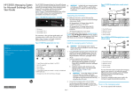
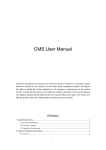
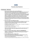
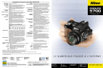
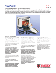
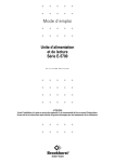
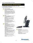
HP E5000 Messaging System
for Microsoft Exchange Quick
Start Guide
Abstract
IMPORTANT:
Read this document first.
A System Recovery DVD is included with your messaging
system. This DVD is used to restore the system to factory
defaults and should be kept in a safe place.
The HP E5000 Messaging System for Microsoft
Exchange is the general name for several E5x00
hardware-software solutions for Microsoft Exchange.
Each messaging system features HP server blades and
dense disk storage combined in a single 3U chassis, as
shown in Figure 1 (page 1), and Microsoft Exchange
setup utilities. The Microsoft Windows Server 2008 R2
Enterprise Edition SP1 operating system is preinstalled
and activated on all systems.
Rack the messaging system hardware
1.
2.
3. Server blade 2, Bay 2
2. Server blade 1, Bay 1
4. Chassis fault LED
The instructions in this quick start guide apply to all
messaging system models unless otherwise noted.
Figure 2 Rear view
3.
4.
2. HP 2-port Ethernet I/O module (2). These modules connect to
the NIC located on each server blade motherboard.
**5697-1781**
To verify the lever is fully latched, pull on the lever
but do not press the release button. If any lever
appears to be loose, press the lever until it clicks.
Connect the messaging system power cords to the
rack power supply using standard procedures.
Connect the messaging system network
cables
4. SAS I/O module (2)
5. Power button
The EMU provides connections to two types of
management processors:
6. Power supply (2)
•
EMU processor
7. HP 2-port Ethernet I/O module. These modules (2) connect to
the NIC located on top of the Mezzanine card on each server
blade. They are standard on the E5500 and E5700 systems and
optional on the E5300 system.
•
iLO processor for each server blade
8. Management port for iLO and Enclosure Manager Unit (EMU)
•
EMU: 10.0.0.10
•
Server 1 iLO: 10.0.0.11
•
Server 2 iLO: 10.0.0.12
•
Subnet: 255.255.255.0
To simplify initial setup, the EMU and iLO processors
are configured for static addressing as follows:
Page 1
1. Server 1, NIC port 1
6. Server 2, Mezz NIC, port 2
2. Server 2, NIC port 1
7. Server 1, Mezz NIC, port 2
3. Server 1, NIC port 2
8. Server 2, Mezz NIC, port 1
4. Server 2, NIC port 2
9. Server 1, Mezz NIC, port 1
5. E5000 enclosure power 10. Enclosure Manager NIC (includes
button
iLO connections for both servers)
By default, the HP E5000 Configuration Wizard sets up
the Client/MAPI and Replication networks as follows:
•
Ensure that the disk drives are fully seated in the
disk drive drawer and expansion disk enclosures.
1. System fan
3. Drive fan
HP Part Number: 5697-1781
Published: May 2012
Edition: 4
If you ordered the messaging system without the
rack, install the rail kit and messaging system
chassis by following the HP StorageWorks 3U
Storage System Rail Kit Installation Instructions,
packaged with the rail kit.
Install any expansion disk enclosures.
a. Add expansion disk enclosures to the rack by
following the HP StorageWorks 2U Storage
System Rail Kit Installation Instructions,
packaged with the rail kit.
b. Cable the expansion disk enclosures to the
messaging system chassis. For recommended
cabling, see the HP E5000 Messaging System
for Microsoft Exchange Administrator Guide.
IMPORTANT: Ensure that cabling in the
back of the rack does not interfere with
system operation or maintenance. Bind
cables loosely with cable ties and route
excess cable out of the way, along the side
of the rack.
See Figure 2 (page 1) to locate components referenced
elsewhere in this guide.
© Copyright 2012 Hewlett-Packard Development Company, L.P.
Printed in Puerto Rico
Figure 3 Messaging system network ports
WARNING! The messaging system is heavy.
Always use at least two people to move the
storage system into the rack.
Figure 1 Front view
1. Disk drawer
Figure 3 (page 1) identifies the network ports on the
rear of the messaging system.
•
Client/MAPI network
◦
Server 1/Port 1 and Server 2/Port 2 network
ports connect to this network.
◦
This network is labeled as the MAPI network on
each server.
◦
The default setting is static, but you can use the
Configuration Wizard to configure DHCP
addressing.
Replication network
◦
Server 1/Port 2 and Server 2/Port 1 network
ports connect to the replication network.
◦
The Configuration Wizard automatically sets
these static addresses by default (but also allows
you to change them):
– Server 1: 10.0.0.1
– Server 2: 10.0.0.2
NOTE: If connecting to a switch, the
Network configuration will need to change
to be compatible with the network settings.
Use one of the Ethernet cables shipped with the
E5000 system to connect the Replication network
ports, see Figure 4 (page 2) or Figure 5 (page
2).
Figure 4 (page 2) shows the recommended E5300
Messaging System network configuration expected by
the E5000 Configuration Wizard.
Figure 4 Typical E5300 network configuration
1. Client/MAPI Network
3. Domain Controller
2. Replication Network
4. Connection to EMU
Figure 5 (page 2) shows the typical E5500/E5700
network configuration expected by the E5000
Configuration Wizard.
unplugged from a NIC port, and therefore may not be
cause for concern.
See the HP E5000 Messaging System for Microsoft
Exchange Administrator Guide for network options.
Configure the iLO and EMU network ports
Access the messaging system
1.
Connect a system (the configuration system) in the
environment or a laptop to the EMU port (8,
Figure 2 (page 1)).
Connect to the messaging system using either the remote
console (iLO) or a direct (KVM) connection. The iLO
remote console is the recommended method.
HP strongly recommends that you also install Insight
Remote Support as described in the HP E5000
Messaging System for Microsoft Exchange Administrator
Guide.
Use an Ethernet cable connected directly to the
system or through a switch.
Configure the NIC on your system to a static
address of 10.0.0.20 with the subnet mask
255.255.255.0.
Configure iLO on blade 1. Open a web browser
and log in to iLO using the address http://
10.0.0.11 and the Administrator password from
the blade pull-out tab in the front of the messaging
system.
Configure iLO networking settings using the tools
under Administration in the iLO management
interface. Optionally change the Administrator
password before changing the network settings.
After completing your changes, click Apply to save
your settings.
Configure iLO on blade 2. Open a web browser
and log in to iLO using the address http://
10.0.0.12. Repeat steps 4 and 5.
Connect to the Enclosure Manager software using
a secure shell application (PuTTY, for example). Log
in to the EMU with the EMU IP address (10.0.0.10),
port (22), and connection type (SSH). When
prompted, enter the Administrator password on the
tear-away label attached to the top left rear of the
enclosure. Configure the following:
a. Change your EMU Administrator password by
typing set password at the command line
prompt (recommended).
b. To change the static IP address, type the
command set ipconfig static at the
command line prompt and follow the
instructions.
c. To change the EMU addressing to DHCP, type
set ipconfig dhcp at the command line
prompt.
For instructions on using each access method, see the
HP E5000 Messaging System for Microsoft Exchange
Administrator Guide or the HP Integrated Lights-Out User
Guide.
Supporting documentation
2.
3.
Figure 5 Typical E5500/E5700 network configuration
4.
5.
6.
1. Client/MAPI network
4. Connection to EMU
2. Replication network
5. Management network
3. Connections to management
network
Power on the messaging system
1.
2.
Power on expansion disk enclosures, if any.
Power on the messaging system by pushing the
power button on the back of the chassis, as shown
in Figure 2 (page 1).
Approximately 30 seconds after the messaging
system is powered on, the server blades should start
to power on automatically. During this time, the
Enclosure Manager (EM) fault LED flashes amber.
After the EM has powered on, the EM fault LED
turns off and the EM health LED turns solid green.
Then, the server blades should start to power on.
Once the messaging system power is on, turn on the
server blades if they do not automatically power on. The
amber chassis fault LED (4, Figure 1) flashes if any
component fault is detected by the System Management
Homepage. A fault can be as minor as a cable
7.
Configure the messaging system software
The messaging system should be powered up and the
network ports cabled for your network configuration,
including the EMU port. Complete the following steps,
first on server 1 and then on server 2. Do not start on
server 2 until you have completed the steps on server 1.
1. Enter your locale information in the Windows setup
dialog and accept the license terms. The Windows
setup completes in approximately 15 minutes, and
the HP E5000 Configuration Wizard starts.
2. Enter and confirm the server Administrator
password. The Administrator password is required
only the first time you run the wizard. Click Next.
3. Step through each menu option in the wizard to
complete the minimum required configuration.
4. After you enter your EMU Administrator password,
the wizard displays the status of tasks it must
complete before continuing. If the wizard finds
errors, it reports them and stops. Exit the wizard,
fix the errors, and restart the wizard from the
Program Files menu on your system.
5. When the Summary screen appears, review the
summary report. Click Apply Settings to apply the
configuration settings or Back to modify them.
6. When you are ready to accept the settings, press
Finish to reboot the server. If you do not want to
reboot at this time, clear the box Reboot after
exiting the wizard.
7. Run the Exchange Deployment Tool to configure
Exchange Server 2010 on server 1. For instructions,
see the HP E5000 Messaging System for Microsoft
Exchange Administrator Guide.
8. Complete the E5000 Configuration Wizard and
the E5000 Exchange Deployment Tool for server
2. Start the Configuration Wizard from the Program
Files menu on your system.
NOTE: You cannot connect to iLO or the EMU
from the configuration system until you change
the network settings on the configuration system.
HP recommends that you configure the EMU so that
administrators have remote network access to the unit.
The messaging system is now ready for use.
Page 2
IMPORTANT: Be sure to install any available
software updates as described in the HP E5000
Messaging System for Microsoft Exchange
Administrator Guide.
•
HP E5000 Messaging System for Microsoft
Exchange Administrator Guide
•
HP E5000 Messaging System for Microsoft
Exchange Release Notes
•
HP StorageWorks 3U Storage System Rail Kit
Installation Instructions (to install rails and rack the
messaging system chassis)
•
HP StorageWorks 2U Storage System Rail Kit
Installation Instructions (to rack expansion disk
enclosures)
You can also find these documents from the Manuals
page of the HP Business Support Center website:
http://www.hp.com/support/manuals
Select Solution appliances in the Solutions group and
then select your product. Localized versions of this quick
start guide are also located on the Manuals page.
To find the iLO documentation, go to www.hp.com/go/
iLO and select More iLO Documentation.