1
HP UPS Management Module
User Guide
Part Number 435656-002
September 2007 (Second Edition)
© Copyright 2007 Hewlett-Packard Development Company, L.P.
The information contained herein is subject to change without notice. The only warranties for HP products and services are set forth in the express
warranty statements accompanying such products and services. Nothing herein should be construed as constituting an additional warranty. HP
shall not be liable for technical or editorial errors or omissions contained herein.
Confidential computer software. Valid license from HP required for possession, use or copying. Consistent with FAR 12.211 and 12.212,
Commercial Computer Software, Computer Software Documentation, and Technical Data for Commercial Items are licensed to the U.S.
Government under vendor’s standard commercial license.
Microsoft, Windows, and Windows NT are U.S. registered trademarks of Microsoft Corporation. Windows Server 2003 is a trademark of
Microsoft Corporation. Intel, Pentium, and Itanium are trademarks or registered trademarks of Intel Corporation or its subsidiaries in the United
States and other countries.
Audience assumptions
This document is for the person who installs and maintains power products. HP assumes you are qualified
in the servicing of high-voltage equipment and trained in recognizing hazards in products with hazardous
energy levels.
Contents
Overview..................................................................................................................................... 7
Introduction .............................................................................................................................................. 7
Features ................................................................................................................................................... 7
HP UPS Power Protection Agent overview ..................................................................................................... 8
HP UPS Power Protection Agent requirements ...................................................................................... 8
Typical hardware configurations ................................................................................................................. 9
Configuration A ............................................................................................................................ 10
Configuration B............................................................................................................................. 10
Configuration C ............................................................................................................................ 11
Configuration D ............................................................................................................................ 12
Configuration E ............................................................................................................................. 13
Configuration F ............................................................................................................................. 14
Configuration G ............................................................................................................................ 15
Web interface requirements...................................................................................................................... 15
Component identification ............................................................................................................. 17
Front panel ............................................................................................................................................. 17
Installing the HP UPS Management Module ................................................................................... 18
Required tools......................................................................................................................................... 18
Installing the management module ............................................................................................................. 18
Checking the Error LED ............................................................................................................................ 20
Connecting the network cable................................................................................................................... 20
Connecting the configuration cable ........................................................................................................... 21
Launching a terminal emulation program .................................................................................................... 21
Configuring the management module for remote access ............................................................................... 22
Connecting devices ................................................................................................................................. 23
Installing the HP UPS Power Protection Agent ................................................................................. 26
Installation overview ................................................................................................................................ 26
Installing the agent on Windows operating systems ..................................................................................... 26
Installing the agent using the GUI method ......................................................................................... 27
Installing the agent using the silent installation method........................................................................ 31
Reconfiguring the agent on Windows operating systems .............................................................................. 32
Installing the agent on Linux operating systems............................................................................................ 33
Installing the agent using the installation script................................................................................... 33
Installing the agent using the silent installation method........................................................................ 34
Installing the agent on SLES 10 ....................................................................................................... 35
Installing the agent on an Itanium system .......................................................................................... 36
Reconfiguring the agent on Linux operating systems ..................................................................................... 36
Installing the agent on HP-UX operating systems .......................................................................................... 36
Installing the agent locally or remotely using the Installation Script method ............................................ 37
Installing the agent locally or remotely using the SAM method ............................................................. 37
Installing the agent using the silent installation method........................................................................ 38
Reconfiguring the agent on HP-UX operating systems ................................................................................... 39
Uninstalling components from Windows® systems ....................................................................................... 39
Uninstalling components from Linux systems ................................................................................................ 39
Contents
3
Uninstalling components from HP-UX systems .............................................................................................. 39
HP UPS Management Module web interface .................................................................................. 41
HP UPS Management Module web interface overview ................................................................................. 41
Accessing the web interface ..................................................................................................................... 41
Web browser ............................................................................................................................... 41
System tray icon ............................................................................................................................ 42
Signing in to the web interface.................................................................................................................. 42
Browser security alert............................................................................................................................... 43
Establishing a secure session for Internet Explorer .............................................................................. 44
Secure session for Mozilla or SeaMonkey......................................................................................... 44
Establishing a secure session for Firefox ........................................................................................... 45
Navigating the web interface.................................................................................................................... 45
Home tab ............................................................................................................................................... 46
Overview menu............................................................................................................................. 46
Alarms menu................................................................................................................................. 48
Identification menu ........................................................................................................................ 49
Parameters menu ........................................................................................................................... 51
Manual Control menu .................................................................................................................... 53
Logs tab ................................................................................................................................................. 54
Event Log menu ............................................................................................................................. 54
Application Log menu .................................................................................................................... 56
Setup tab ............................................................................................................................................... 57
My Account menu ......................................................................................................................... 57
User Accounts menu ...................................................................................................................... 58
Network menu .............................................................................................................................. 59
Network Management menu........................................................................................................... 60
Event Notifications menu ................................................................................................................ 64
Attached Devices menu .................................................................................................................. 67
Power Fail menu............................................................................................................................ 71
Shutdown Events menu ................................................................................................................... 73
Scheduled Shutdowns menu............................................................................................................ 74
Help tab................................................................................................................................................. 75
About menu .................................................................................................................................. 76
Contents menu .............................................................................................................................. 77
Info & Updates menu ..................................................................................................................... 77
HP UPS Management Module Service Menu .................................................................................. 78
HP UPS Management Module Service Menu overview ................................................................................. 78
Accessing the Service Menu ..................................................................................................................... 78
Telnet session................................................................................................................................ 78
Terminal emulation session ............................................................................................................. 79
POST ..................................................................................................................................................... 79
Navigating the menus.............................................................................................................................. 79
Service Menu.......................................................................................................................................... 80
HP UPS Management Module Configuration Utility ...................................................................................... 80
UPS Monitor submenu .................................................................................................................... 80
Network Configuration submenu ..................................................................................................... 81
System Configuration submenu........................................................................................................ 84
User Accounts submenu.................................................................................................................. 85
Troubleshooting .......................................................................................................................... 87
ASCII character sequence Esc+Shift+9 directs all serial communication to the iLO port for the HP ProLiant DL380
G4 ........................................................................................................................................................ 87
Contents
4
Agent does not install on RH Itanium.......................................................................................................... 87
Attached device communication errors appear............................................................................................ 87
Attached device did not shut down gracefully ............................................................................................. 87
Battery Test did not run ............................................................................................................................ 88
Browser does not display the web interface for an installed management module ............................................ 88
Browser incorrectly displays English or Japanese characters ......................................................................... 88
Certificate error....................................................................................................................................... 89
Email notifications are not received from an HP-UX server............................................................................. 89
Error LED illuminates or flashes.................................................................................................................. 89
Event notification messages do not appear on console screen ....................................................................... 90
Event notifications are not being sent ......................................................................................................... 90
FTP error messages appear when connecting through Linux .......................................................................... 90
Flash update fails over a serial connection.................................................................................................. 90
HP SIM lists a discovered UPS as Unmanaged in the System Type column ...................................................... 90
HPFlash does not install image.bin on a Pentium III ...................................................................................... 91
Initiate Battery Test Command Has Been Sent message not displayed............................................................. 91
Input frequency shows zero ...................................................................................................................... 91
InstallShield error code -6001 appears during setup .................................................................................... 91
Invalid IP address .................................................................................................................................... 92
Links in traps and emails do not work correctly for Linux............................................................................... 92
Linux agent does not execute on Red Hat 5 ................................................................................................ 92
Low battery warning is displayed .............................................................................................................. 92
Manual Load Dumped alarm not working................................................................................................... 92
Messages from the Messenger Service are not displayed in Japanese ............................................................ 92
Network attached UPS not discovered ....................................................................................................... 92
No power .............................................................................................................................................. 93
Non-admin users cannot log in through telnet.............................................................................................. 93
On battery alarm .................................................................................................................................... 93
On boost alarm....................................................................................................................................... 93
On buck alarm ....................................................................................................................................... 93
Operating system firewall prevents management module functionality ............................................................ 93
Overload alarm ...................................................................................................................................... 93
Receiving a security error ......................................................................................................................... 94
Redundant status error displays on the Attached Devices screen for a nonredundant configuration..................... 94
Redundant UPS status .............................................................................................................................. 94
SLES 10 agent does not autostart after power fail or reboot .......................................................................... 95
Servers running Windows® Server 2003 do not restart................................................................................ 95
Shutdowns not functioning when Any Server is configured in a redundant configuration ................................... 95
Silent install did not execute successfully..................................................................................................... 95
Task Bar menu does not clear ................................................................................................................... 96
UPS Power Protection Agent does not display a shutdown warning message in SLES operating systems.............. 96
Unable to discover a UPS ......................................................................................................................... 96
Unable to edit devices using telnet............................................................................................................. 96
Unable to locate the .INI files for a silent install ........................................................................................... 96
Unable to obtain a valid network address error message displays ................................................................. 97
Unable to reboot the machine ................................................................................................................... 97
Unable to set event delays using telnet ....................................................................................................... 97
Unable to start the HP UPS Power Protection Agent for Linux ......................................................................... 97
Unexpected problems occur with the web interface and Service menu ........................................................... 98
Utility alarm............................................................................................................................................ 98
When resetting or powering on the management module, the browser does not display the web interface ......... 98
Technical support........................................................................................................................ 99
Before you contact HP.............................................................................................................................. 99
Contents
5
HP contact information ............................................................................................................................. 99
Regulatory compliance notices ................................................................................................... 100
Regulatory compliance identification numbers ........................................................................................... 100
Federal Communications Commission notice............................................................................................. 100
FCC rating label.......................................................................................................................... 100
Class A equipment....................................................................................................................... 100
Class B equipment ....................................................................................................................... 100
Declaration of conformity for products marked with the FCC logo, United States only..................................... 101
Modifications........................................................................................................................................ 101
Canadian notice (Avis Canadien)............................................................................................................ 101
European Union regulatory notice ........................................................................................................... 102
Japanese notice .................................................................................................................................... 103
BSMI notice .......................................................................................................................................... 103
Alert messages ......................................................................................................................... 104
UPS alarms........................................................................................................................................... 104
Systems Insight Manager integration ........................................................................................... 107
Systems Insight Manager overview .......................................................................................................... 107
Discovering the management module....................................................................................................... 108
Configuring HP SIM to receive traps ........................................................................................................ 108
Configuring the management module to send traps to HP SIM..................................................................... 109
Security considerations .............................................................................................................. 110
Security considerations overview ............................................................................................................. 110
Optional power monitoring using SNMP ..................................................................................... 111
SNMP monitoring.................................................................................................................................. 111
Updating the firmware .............................................................................................................. 112
Updating the firmware overview.............................................................................................................. 112
Redundant configuration............................................................................................................ 113
Configuring the software for redundancy.................................................................................................. 113
Mass configuration ................................................................................................................... 115
Using the HP UPS Management Upgrade Utility ........................................................................................ 115
Acronyms and abbreviations...................................................................................................... 116
Index....................................................................................................................................... 118
Contents
6
Overview
Introduction
The HP UPS Management Module enables you to monitor, manage, and control power environments of
up to five devices through the serial connectors located on the front of the management module. Multiple
devices can monitor the UPS over the network connection. The management module can be configured to
send alert traps to HP Systems Insight Manager and other SNMP management programs or used as a
stand-alone management system.
For configuration and status monitoring, the management module includes:
•
HP UPS Management Module web interface (on page 41)—A graphical interface that is accessed
with a web browser
•
HP UPS Management Module Service Menu (on page 78)—A text-based menu that is accessed
through telnet or a terminal emulation session
For a detailed list of supported UPSs, see the HP website (http://www.hp.com/go/rackandpower).
Features
•
Monitors the status of the UPS and performs diagnostics
•
Manages a graceful shutdown of attached equipment during a utility power failure
•
Manages independent UPS load segments to provide separate power control of connected
equipment
•
Prioritizes the timing of equipment shutdown and reboots connected equipment by load segment
•
Delays restart by load segment after a power outage to sequence the startup of system components
•
Shuts down and reboots the UPS and attached equipment, based on a user-specified schedule
•
Sends customized email and broadcast notification messages and SNMP traps
•
Issues computer commands at power failure
•
Displays logs for analysis
•
Supports a redundant UPS configuration
•
Includes enhanced HP SIM integration
•
Includes multi-language support
•
Supports serial- and network-attached server communications
•
Supports a customizable Events script
Overview 7
HP UPS Power Protection Agent overview
The HP UPS Power Protection Agent runs on a local or network server and allows the management
module to gracefully shut down the operating system of that server and optionally run a script during
power failure. Install the agent on any machine that is powered by the UPS and any machine that the
management module uses to initiate a command.
NOTE: If you are an existing HP Power Manager user, you must uninstall the HPPM Remote
Agent before installing the UPS Power Protection Agent.
If the UPS Power Protection Agent is not applicable for your load devices, you can use a third-party
SNMP manager to monitor the power protection. For more information, see "SNMP monitoring (on page
111)."
HP UPS Power Protection Agent requirements
NOTE: For the latest supported operating systems, see the HP website
(http://www.hp.com/go/rackandpower).
Hardware and software
Suggested minimum requirements
Hardware
200-MHz processor
Disk space
10 MB free disk space
System memory
64 MB of RAM
Operating system (32-bit)
Microsoft® Windows® XP Professional with Service Pack 2
Microsoft® Small Business Server 2000 with Service Pack 4
Microsoft® Windows® 2000 Server and Advanced Server with Service Pack 4
Microsoft® Windows® Server 2003 Standard Edition x86 with Service Pack 2
Microsoft® Windows® Server 2003 Enterprise Edition x86 with Service Pack 2
Microsoft® Windows® Small Business Server 2003, Standard and Premium
Editions x86 with Service Pack 2
Red Hat Enterprise Linux 4 for x86 with Update 5
Red Hat Enterprise Base Server/Advanced Platform Linux 5 for x86
SUSE Linux Enterprise Server 9 for x86 with Service Pack 3
SUSE Linux Enterprise Server 10 for x86 with Service Pack 1
Operating system (64-bit)
Microsoft® Windows® Server 2003 for AMD64 and Intel® EM64T with
Service Pack 2
Microsoft® Windows® Server 2003 Enterprise Edition For Itanium®-based
Systems with Service Pack 2
Red Hat 4 for Itanium® with Update 5
Red Hat Enterprise AS/ES Linux 4 for AMD64 and Intel® EM64T with Update 5
Red Hat Enterprise Base Server/Advanced Platform Linux 5 for Itanium®
Red Hat Enterprise Base Server/Advanced Platform Linux 5 for AMD64 and
Intel® EM64T
Overview 8
Hardware and software
Suggested minimum requirements
SUSE Linux Enterprise Server 9 for AMD64 and Intel® EM64T with Service Pack
3
SUSE Linux Enterprise Server 9 for Itanium® with Service Pack 3
SUSE Linux Enterprise Server 10 for AMD64 and Intel® EM64T with Service
Pack 1
SUSE Linux Enterprise Server 10 for Itanium® with Service Pack 1
HP-UX 11.0 for HP 9000 with patch bundle HPUX_800_11.0_11081152,
PHCO_28112*
HP-UX 11i v1 (11.11) with the following patches for all v1 machines: PHNE
28799, PHNE_29887, PHSS_22535*
Patches for B2000 machines include the v1 patches, plus the following patches:
PHKL_28253, PHSS_28547, PHSS_28548*
HP-UX 11i v2 (11.23) with the latest patch bundle*
* For the latest updates of HP-UX patches, see the HP Patch Firmware Database website
(http://www1.itrc.hp.com/service/patch/mainPage.do).
Typical hardware configurations
The management module can be attached in any of the following configurations:
•
Configuration A (on page 10)—UPS connected serially to devices that monitor, manage, and control
the UPS
•
Configuration B (on page 10)—UPS connected to devices that monitor the UPS over the network.
•
Configuration C (on page 11)—UPS connected serially to devices that monitor, manage, and control
the UPS, and connected to devices that monitor the UPS over the network
•
Configuration D (on page 12)—Redundant UPS configuration with serial connections
•
Configuration E (on page 13)—Redundant UPS configuration with network connections
•
Configuration F (on page 14)—Redundant UPS configuration with serial and network connections
•
Configuration G (on page 15)—Redundant UPS configuration with dual subnet
Overview 9
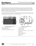
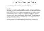
Configuration A
This figure illustrates a UPS with a management module installed that is serially attached to a server
running the UPS Power Protection Agent. The server is plugged into a load segment of the UPS, and is
able to monitor, manage, and control the UPS.
Item
Description
1
Server with UPS Power Protection Agent installed
2
UPS with management module installed
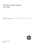
Configuration B
This figure illustrates a UPS with a management module installed that is connected to the network. A
server on the same network running the UPS Power Protection Agent monitors the UPS.
Overview 10
Item
Description
1
Server with UPS Power Protection Agent installed
2
Network
3
UPS with management module installed
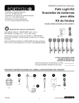
Configuration C
This figure illustrates a UPS with a management module installed that is serially attached to a server
running the UPS Power Protection Agent. The server is plugged into a load segment of the UPS, and is
able to monitor, manage, and control the UPS. The management module is also connected to a network
where another server running the UPS Power Protection Agent monitors the UPS.
Item
Description
1
Network server with UPS Power Protection Agent
installed
2
Server with UPS Power Protection Agent installed that is
serially attached to the UPS
3
UPS with management module installed
4
Network
Overview 11
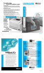
Configuration D
This figure illustrates a redundant configuration with serial connections.
Item
Description
1
UPS A
2
Server
3
Network
4
UPS B
Power connection
Communication path
Overview 12
Configuration E
This figure illustrates a redundant configuration with network connections.
Item
Description
1
UPS A
2
UPS B
3
Server
4
Network
Power connection
Communication path
Overview 13
Configuration F
This figure illustrates a redundant configuration with serial and network connections.
Item
Description
1
UPS A
2
Server
3
Network
4
UPS B
Power connection
Communication path
Overview 14
Configuration G
This figure illustrates a redundant configuration with dual subnet.
Item
Description
1
Subnet A
2
UPS A
3
Server
4
Subnet B
5
UPS B
Power connection
Communication path
Web interface requirements
The following table lists the minimum requirements necessary to operate the web interface.
Software
Browser
Web browser on a Microsoft® operating systems
client
• Microsoft® Internet Explorer 6.0 with Service Pack 1
(32-bit only)
•
Microsoft® Internet Explorer 7.0 (32-bit only)
Red Hat Linux operating system (32-bit only)
•
Firefox 1.5.x
•
SeaMonkey 1.0.1
SUSE Linux operating system (32-bit only)
•
Firefox 1.5.x
•
Mozilla 1.7.8
Overview 15
Software
Browser
Monitor resolution
Minimum supported resolution of 1024 x 768, 16-bit
high color (maximize browser window for optimal
display)
Overview 16
Component identification
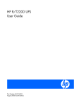
Front panel
Item
Description
1
Serial device connectors
2
Environmental connector (for future use)
3
Power LED
4
Error LED
5
Reset button
6
Network connector
7
Config/Pass-Thru connector
Component identification
17
Installing the HP UPS Management Module
Required tools
No. 2 Phillips screwdriver
Installing the management module
NOTE: It is not necessary to power down the UPS before installing the management module.
1.
Disconnect the communications cable from the option card.
2.
Remove the two screws securing the option card or cover plate and slide the card or plate out.
Installing the HP UPS Management Module 18
3.
Install the management module along the alignment channels in the option slot.
4.
If the UPS is powered up, you can be sure that the management module is seated properly and
receiving power by verifying that the Power LED is illuminated solid green.
5.
Secure the management module using the two screws you removed in step 2.
Installing the HP UPS Management Module 19
Checking the Error LED
If the Error LED illuminates red or flashes red, see the "Troubleshooting (on page 87)" section for more
information.
Connecting the network cable
Connect a standard Ethernet cable between the network connector on the management module and a
network jack.
This connection is used to access the management module remotely through telnet or the web interface.
The management module also uses the network connection to communicate to the configured agents and
to facilitate SNMP-based monitoring.
Installing the HP UPS Management Module 20
Connecting the configuration cable
1.
Connect a DB-9 to RJ-45 adapter to a serial connector on the host computer.
2.
Connect one end of an RJ-45 cable to the RJ-45 connector on the adapter.
3.
Connect the other end of the RJ-45 cable to the Config/Pass-Thru connector on the management
module.
This connection is used to configure and access the management module locally through a terminal
emulation program.
Launching a terminal emulation program
NOTE: HyperTerminal is the serial communication program provided with Microsoft®
Windows® and is used in this section as an example for setting up a terminal emulation
session. If you are using another utility, the steps might be different.
Installing the HP UPS Management Module 21
1.
On the host computer, click Start, and select
Programs>Accessories>Communications>HyperTerminal.
The Connection Description window appears.
2.
Enter a description, select an icon for the connection, and then click OK. The Connect To window
appears.
3.
Select the serial connector on the host computer to which the DB-9 to RJ-45 adapter is attached, and
then click OK. The COM Properties window appears.
4.
Select the following parameter values, and then click OK.
o
Bits per second—115200
o
Data bits—8
o
Parity—None
o
Stop bits—1
o
Flow control—None
Configuring the management module for remote
access
1.
Be sure that you have connected the network cable ("Connecting the network cable" on page 20) to
the management module.
2.
Be sure that you have connected the configuration cable ("Connecting the configuration cable" on
page 21) to the management module and the host computer with an open terminal emulation
session.
3.
Press the Reset button on the management module front panel.
On the terminal emulation session screen running on the host computer, the POST executes, and the
following prompt appears:
Press any key in 5 seconds to enter Service menu.
4.
Press a key to enter the HP UPS Management Module Service Menu.
Installing the HP UPS Management Module 22
Use the HP UPS Management Module Service Menu to configure the minimum settings required to
access the management module remotely using telnet or the web interface. You can configure other
settings using this utility in conjunction with a terminal emulation program or a telnet connection.
NOTE: If your network is configured with a BOOTP server, the network settings are
automatically assigned. Verify and note the assigned values.
5.
If your network is not configured with a BOOTP server:
a. On the Main menu, enter 1 at the prompt to open Module Configuration submenu.
b. Enter 2 at the prompt to enter the Network Configuration submenu.
c.
Enter 1 at the prompt to enter the Network Settings submenu.
6.
From this menu, change the mode used to acquire a network IP address to Static IP. You can also
change the IP address, subnet mask, and default gateway of the HP UPS Management Module.
7.
Configure web access:
a. On the Network Configuration submenu, enter 3 at the prompt to open the Web Access
submenu.
b. Use the submenu options to select HTTP (default) or HTTPS and configure the associated port. The
default port for HTTP is port 80, and the default port for HTTPS is port 443.
8.
Configure telnet access:
a. On the Network Configuration submenu, enter 2 at the prompt to open the Remote Console
submenu.
b. Use the submenu options to configure the telnet port. The default port is port 23.
9.
Enter 0 at the prompt until you have returned to the Main menu.
10.
Enter s at the prompt to save the changes and restart the management module.
11.
Enter 2 at the prompt to close the configuration utility.
Connecting devices
NOTE: The management module ships with one DB-9 to RJ-45 adapter for management
module configuration. Five additional adapters for connecting serial devices are available for
purchase in the adapter kit (part number AF402A).
1.
Connect a DB-9 to RJ-45 adapter to a serial connector on the device.
Installing the HP UPS Management Module 23
2.
Connect one end of a network cable to the RJ-45 connector on the adapter.
3.
Connect the other end of the network cable to a serial device connector on the management module.
Note the connector number on the management module to which the device is connected.
4.
Connect the device to a UPS load segment receptacle using the device input power cord or a jumper
cable.
Installing the HP UPS Management Module 24
5.
Press the Reset button on the management module front panel.
Installing the HP UPS Management Module 25
Installing the HP UPS Power Protection Agent
Installation overview
Install the UPS Power Protection Agent on any machine that is powered by the UPS and any machine that
the management module uses to initiate a command. There are three installation options:
•
GUI installation—A series of dialog boxes and prompts guide you through the installation process.
•
Non-GUI installation—A series of commands are necessary to complete the installation.
•
Silent installation—A preconfigured initialization file is specified during installation. This file contains
all the information a user is typically prompted to enter.
Silent installation is typically used by system administrators who have many installations that are
configured identically and require minimal user interaction. During a silent installation you will:
o
Install an agent through the assisted installation method that is appropriate for the operating
system.
o
Configure the agent exactly as the final replicated systems should be configured.
o
Use the DevManRA.ini file that is generated in the directory of the application as a template in
the agent silent install process.
o
Change any items that should be unique, such as the Management Server IP address, through
the normal operation of the software.
The following table summarizes the available installation options for each operating system.
Operating
system
GUI
installation
Non-GUI
installation
Silent
installation
Local/remote
installation
Windows®
Available
-
Available
-
Linux
-
Available
Available
-
HP-UX
-
Available
Available
Available
NOTE: If you are an existing HP Power Manager user, you must uninstall the HPPM Remote
Agent before installing the UPS Power Protection Agent.
Installing the agent on Windows operating systems
The UPS Power Protection Agent can be installed using the GUI or silent installation methods on any
supported Windows® operating system.
IMPORTANT: To ensure your system has the minimum requirements needed to run the agent,
see "UPS Power Protection Agent requirements ("HP UPS Power Protection Agent requirements"
on page 8)."
Installing the HP UPS Power Protection Agent
26
NOTE: You might need to reboot after installing the agent on Windows®.
Installing the agent using the GUI method
1.
Insert the HP Infrastructure Management Pack CD into the CD-ROM drive of the computer. If the
AutoPlay feature is enabled, the installation menu automatically starts. If the AutoPlay feature is
disabled, explore the CD, and double-click AUTORUN.EXE in the root folder.
If the software has been downloaded from the HP website (http://www.hp.com/go/rackandpower),
follow the instructions to unpack the files, then locate and run SETUP.EXE.
2.
Select HP UPS Management Module from the side menu.
3.
Select UPS Power Protection Agent.
The Welcome screen appears.
4.
Read the introduction, and then click Next.
The License Agreement screen appears.
Installing the HP UPS Power Protection Agent
27
5.
Read the license agreement, select I accept the terms in the license agreement, and then click Next.
The Customer Information screen appears.
6.
Enter your customer information, and then click Next.
The Choose Destination Location screen appears.
Installing the HP UPS Power Protection Agent
28
7.
Click Next to install the agent in the default folder that is displayed. To specify a different folder,
click Change, navigate to the appropriate folder, and then click Next.
The Ready to Install the Program screen appears.
8.
Click Install. The wizard installs the software.
Installing the HP UPS Power Protection Agent
29
9.
Click Finish to complete the install wizard and continue with the configuration process.
NOTE: It might take a moment for the configuration screen to appear. If there are open
windows on the desktop, you might need to minimize the windows to view the configuration
screen.
10.
Enter the valid host name, IP address, or communications port of the management module in the
Management Server 1 field. This setting ensures that a particular management module executes
commands and operating system shutdowns on the computer running the agent.
If security is not a concern, leave this field blank.
11.
To enable a redundant configuration, enter the host name, IP address, or communications port of the
second management module in the Management Server 2 field.
IMPORTANT: If you are configuring redundant management modules, do not select Any Server
in either dropdown box.
Installing the HP UPS Power Protection Agent
30
12.
Click Finish to close the configurator.
The service starts automatically. Wait until the system tray icon displays a green check mark
begin using the software.
to
NOTE: An icon in the Windows® system tray shows the status of the management module. It
appears if the
might take a few moments for the icon to change. A green check mark
management module is communicating with the agent without errors. If the service has
stopped, a blue hexagon icon
appears. A red icon
appears if the software is not
configured, the UPS is not connected, or the agent and management module are not
communicating. Hover over the icon with the mouse pointer, and a tool tip displays a status
message. For more information about the system tray icon status messages, see "System tray
icon (on page 42)."
NOTE: To reconfigure the agent, see "Reconfiguring the agent on Windows® Operating
Systems ("Reconfiguring the agent on Windows operating systems" on page 32)."
Installing the agent using the silent installation method
Silent installation is typically used by system administrators who have many installations that are
configured identically and require minimal user interaction. During a silent installation you will:
•
Install an agent through the assisted installation method that is appropriate for the operating system.
•
Configure the agent exactly as the final replicated systems should be configured.
NOTE: You must configure the IP address of the management module. Create a DevManRA.ini
file for each site. This points each agent to the correct management module and is the more
secure option.
•
Use the DevManRA.ini file that is generated in the directory of the application as a template in the
agent silent install process.
Installing the HP UPS Power Protection Agent
31
•
Change any items that should be unique, such as the Management Server IP address, through the
normal operation of the software.
To install the agent using the silent installation method:
1.
Create a temporary directory.
2.
Copy the following files into the temporary directory you just created:
3.
o
DevManRA.ini—During an assisted install, this file is landed in the same folder in which the
agent is installed.
o
Setup.exe—This file is included with the installation files on the HP Infrastructure Management
Pack CD and the software download package on the HP website
(http://www.hp.com/go/rackandpower).
o
Setup.iss—This file is included with the installation files on the HP Infrastructure Management
Pack CD and the software download package on the HP website
(http://www.hp.com/go/rackandpower).
o
SetupRA.exe—This file is included with the installation files on the HP Infrastructure Management
Pack CD and the software download package on the HP website
(http://www.hp.com/go/rackandpower).
From the directory that contains all four files, run Setup.exe /s /f DevManRA.ini to install
silently.
If the .ini file is not located in the same folder as the Setup file, run Setup.exe /s /f <path>
DevManRA.ini, where <path> is the DevManRA.ini file location.
The following command line parameters can be specified and are applicable for both interactive and
silent modes.
Parameter
Function
/s
Performs a silent install.
/r
Reboots the computer at completion of setup. This
option is supported only on Windows® and only for
a silent install.
/f DevManRA.ini
Specifies a configuration .ini file used for clean
installs. When this option is specified, the device
detection and configuration step is omitted.
Reconfiguring the agent on Windows operating
systems
To reconfigure the agent:
•
Right-click the agent system tray icon to display a context menu from which the management service
can be stopped or started. In this menu, you can also:
o
Launch a browser session using the Connect option.
o
Configure new settings using the Configure option.
o
Change the IP address or serial path that the agent uses for the management module.
o
Enable or disable a redundant configuration.
-or-
Installing the HP UPS Power Protection Agent
32
•
Select Configure HP UPS Management Module from the HP UPS Management Module option in the
Start Programs menu.
Installing the agent on Linux operating systems
The UPS Power Protection Agent can be installed using an installation script or the silent installation option
on any supported Linux operating system.
IMPORTANT: To ensure your system has the minimum requirements needed to run the agent,
see "UPS Power Protection Agent requirements ("HP UPS Power Protection Agent requirements"
on page 8)."
Installing the agent using the installation script
1.
The agent can be installed two ways:
o
If installing the software from the HP Infrastructure Management Pack CD, insert the CD into the
CD-ROM drive of the computer. From the console or a terminal window, go to the HP UPS Power
Protection Agent/...Linux/Agent subdirectory. Execute the following installation script:
./SetupRA
o
If downloading the software from the HP website (http://www.hp.com/go/rackandpower),
follow the instructions on the website to unpack the files. Locate the Linux agent installation script
(SetupRA). Execute the following script:
./SetupRA
The script installs the agent and requests information to configure the application. Default values or
valid options are shown in brackets following each prompt.
Installing the HP UPS Power Protection Agent
33
The installer launches a separate configuration program.
The script displays: Please enter a server to allow connections from.
2.
Enter the IP address of the management module or the path to the serial device. This configuration
ensures that only that particular management module executes commands and operating system
shutdowns on the computer running the agent.
The script displays: Please enter a second server to allow connections from.
3.
Enter the IP address of a second management module or the path to the second serial device for
redundant communication.
IMPORTANT: If you are configuring redundant management modules, do not enter an asterisk
to allow any server to connect to the management module.
If you do not want to configure a second connection, enter None.
Installing the agent using the silent installation method
Silent installation is typically used by system administrators who have many installations that are
configured identically and require minimal user interaction. During a silent installation you will:
•
Install an agent through the assisted installation method that is appropriate for the operating system.
•
Configure the agent exactly as the final replicated systems should be configured.
NOTE: You must configure the IP address of the management module. Create a DevManRA.ini
file for each site. This points each agent to the correct management module and is the more
secure option.
•
Use the DevManRA.ini file that is generated in the directory of the application as a template in the
agent silent install process.
Installing the HP UPS Power Protection Agent
34
•
Change any items that should be unique, such as the Management Server IP address, through the
normal operation of the software.
To install the agent using the silent installation method:
1.
Create a temporary directory.
2.
Copy the following files into the temporary directory you just created:
3.
o
DevManRA.ini—During an assisted install, this file is landed in the same folder in which the
agent is installed.
o
EULA.txt—This file is included with the installation files on the HP Infrastructure Management Pack
CD and the software download package on the HP website
(http://www.hp.com/go/rackandpower).
o
SetupRA—This file is included with the installation files on the HP Infrastructure Management
Pack CD and the software download package on the HP website
(http://www.hp.com/go/rackandpower).
o
Uninstall—This file is included with the installation files on the HP Infrastructure Management
Pack CD and the software download package on the HP website
(http://www.hp.com/go/rackandpower).
o
HPRA-4.5-x.i586.rpm—This file is included with the installation files on the HP Infrastructure
Management Pack CD and the software download package on the HP website
(http://www.hp.com/go/rackandpower).
From the directory that contains all five files, run ./SetupRA -s -f <path> DevManRA.ini to
install silently.
Replace <path> with the DevManRA.ini file location.
The following command line parameters can be specified and are applicable for both interactive and
silent modes.
Parameter
Function
-s
Performs a silent install.
-log
Creates an installation log
(/user/local/DevMan/install.log). Default is
disabled for interactive mode and enabled for
silent mode. This option is supported only on Linux.
The installation log is created automatically for
Windows® during silent installations in
\%systemdrive%\setup.log.
-f DevManRA.ini
Specifies a configuration .ini file used for clean
installs. When this option is specified, the device
detection and configuration step is omitted.
Installing the agent on SLES 10
1.
Install the agent using the Linux installation script ("Installing the agent using the installation script"
on page 33).
-orInstall the agent using the Linux silent installation method ("Installing the agent using the silent
installation method" on page 34).
2.
Do one of the following:
Installing the HP UPS Power Protection Agent
35
o
Edit the /etc/sysconfig/boot file and change RUN_PARALLEL="yes" to
RUN_PARALLEL="no" to remove parallel script execution.
-or-
o
Edit the /etc/init.d/.depend.start file and add DevMan: network at the end of the
file to add parallel information for DevMan.
Installing the agent on an Itanium system
1.
Install the ia32* file for your operating system from the supplementary disc.
2.
Install the appropriate library files for your operating system from the compact layer in the following
order:
a. Install the glibc* library file.
b. Install the zlib* library file.
RH4-U3
RH4-U4
RH4-U5
RH5
ia32*
ia32el-1.3-2.ia64.rpm ia32el-1.3-2.ia64.rpm ia32el-1.3-2.ia64.rpm ia32el-1.613.el5.ia64.rpm
glibc*
glibc-2.3.42.19.i686.rpm
glibc-2.3.42.25.i686.rpm
glibc-2.3.42.36.i686.rpm
glibc-2.5-12.i686.rpm
zlib*
zlib-1.2.1.21.2.i386.rpm
zlib-1.2.1.21.2.i386.rpm
zlib-1.2.1.21.2.i386.rpm
zlib-1.2.3-3.i386.rpm
3.
Install the agent using the Linux installation script ("Installing the agent using the installation script"
on page 33).
-orInstall the agent using the Linux silent installation method ("Installing the agent using the silent
installation method" on page 34).
Reconfiguring the agent on Linux operating systems
To configure the management module IP address or serial path for Red Hat Linux, run
/etc/rc.d/init.d/DevMan setup.
To configure the management module IP address or serial path for SUSE Linux Enterprise Server, run
/etc/init.d/DevMan setup.
Installing the agent on HP-UX operating systems
The UPS Power Protection Agent can be installed using an installation script, SAM, or silent installation
option on any supported HP-UX operating system.
IMPORTANT: To ensure your system has the minimum requirements needed to run the agent,
see "UPS Power Protection Agent requirements ("HP UPS Power Protection Agent requirements"
on page 8)."
Installing the HP UPS Power Protection Agent
36
Installing the agent locally or remotely using the Installation
Script method
1.
The agent can be installed two ways:
o
If installing the software from the HP Infrastructure Management Pack CD, insert the CD into the
CD-ROM drive of the computer. From the console or a terminal window, go to the HP UPS Power
Protection Agent/...HP-UX/Agent subdirectory. Execute the following installation script:
./SetupRA
o
If downloading the software from the HP website (http://www.hp.com/go/rackandpower),
follow the instructions on the website to unpack the files. Locate the installation script (SetupRA).
Execute the following script:
./SetupRA
The script installs the agent and requests information to configure the application. Default values or
valid options are shown in brackets following each prompt.
2.
To accept the EULA, enter yes.
The script displays: Please enter a server to allow connections from.
3.
Enter the IP address of the management module or the path to the serial device. This configuration
ensures that only that particular management module executes commands and operating system
shutdowns on the computer running the agent.
The script displays: Please enter a second server to allow connections from.
4.
Enter the IP address of a second management module or the path to the second serial device for
redundant communication.
IMPORTANT: If you are configuring redundant management modules, do not enter an asterisk
to allow any server to connect to the management module.
If you do not want to configure a second connection, enter None.
Installing the agent locally or remotely using the SAM method
1.
From a remote machine, enter sam at the command line prompt.
2.
Click Software Management.
3.
Click Install Software to Local Host.
4.
Change the Source Depot Path to a fully qualified path and depot name.
5.
Select the agent you are about to install.
6.
Select Actions>Install from the top menu, and then click OK and Done.
7.
Click OK to analyze the depot file.
8.
Click OK to install the depot file.
9.
Click Done to complete the installation and continue with the configuration process.
10.
Enter /sbin/init.d/DevMan setup in the terminal, and press the Enter key.
The installer launches a separate configuration program.
The script installs the agent and requests information to configure the application. Default values or
valid options are shown in brackets following each prompt.
Installing the HP UPS Power Protection Agent
37
The script displays: Please enter a server to allow connections from.
11.
Enter the IP address of the management module or the path to the serial device. This configuration
ensures that only that particular management module executes commands and operating system
shutdowns on the computer running the agent.
The script displays: Please enter a second server to allow connections from.
12.
Enter the IP address of a second management module or the path to the second serial device for
redundant communication.
IMPORTANT: If you are configuring redundant management modules, do not enter an asterisk
to allow any server to connect to the management module.
If you do not want to configure a second connection, enter None.
Installing the agent using the silent installation method
Silent installation is typically used by system administrators who have many installations that are
configured identically and require minimal user interaction. During a silent installation you will:
•
Install an agent through the assisted installation method that is appropriate for the operating system.
•
Configure the agent exactly as the final replicated systems should be configured.
NOTE: You must configure the IP address of the management module. Create a DevManRA.ini
file for each site. This points each agent to the correct management module and is the more
secure option.
•
Use the DevManRA.ini file that is generated in the directory of the application as a template in the
agent silent install process.
•
Change any items that should be unique, such as the Management Server IP address, through the
normal operation of the software.
To install the agent on a system running HP-UX using the silent installation method:
1.
Create a temporary directory.
2.
Copy the following files into the temporary directory you just created:
o
DevManRA.ini—During an assisted install, this file is landed in the same folder in which the
agent is installed.
o
EULA—This file is included with the installation files on the HP Infrastructure Management Pack
CD and the software download package on the HP website
(http://www.hp.com/go/rackandpower).
o
SetupRA—This file is included with the installation files on the HP Infrastructure Management
Pack CD and the software download package on the HP website
(http://www.hp.com/go/rackandpower).
o
Uninstall—This file is included with the installation files on the HP Infrastructure Management
Pack CD and the software download package on the HP website
(http://www.hp.com/go/rackandpower).
o
HPRA4.5Buildx.depot—This file is included with the installation files on the HP Infrastructure
Management Pack CD and the software download package on the HP website
(http://www.hp.com/go/rackandpower).
Installing the HP UPS Power Protection Agent
38
3.
From the directory that contains all five files, run ./SetupRA -s -f DevManRA.ini to install
silently.
If the .ini file is not located in the same folder as the SetuprRA file, run ./SetupRA -s -f
<path> DevManRA.ini, where <path> is the DevManRA.ini file location.
The following command line parameters can be specified and are applicable for both interactive and
silent modes.
Parameter
Function
-s
Performs a silent install.
-l
Creates an installation log
(opt/DevMan/install.log). Default is disabled for
interactive mode and enabled for silent mode. The
installation log is created automatically for
Windows® during silent installations in
\%systemdrive%\setup.log.
-f DevManRA.ini
Specifies a configuration .ini file used for clean
installs. When this option is specified, the device
detection and configuration step is omitted.
Reconfiguring the agent on HP-UX operating systems
To reconfigure the management module IP address or serial path, run /sbin/init.d/DevMan setup.
Uninstalling components from Windows® systems
1.
Click Start>Settings>Control Panel.
2.
Open Add/Remove Programs.
3.
Select UPS Power Protection Agent, and then click Change/Remove.
The uninstall wizard launches.
Select Remove Choice, and then click Next.
4.
Follow the prompts in the uninstall wizard to uninstall the software.
NOTE: Some files might remain following the uninstallation and can be removed manually.
Uninstalling components from Linux systems
Execute the uninstall script (./Uninstall).
NOTE: Some files might remain following the uninstallation and can be removed manually.
Uninstalling components from HP-UX systems
Execute the uninstall script (./Uninstall).
Installing the HP UPS Power Protection Agent
39
NOTE: Some files might remain following the uninstallation and can be removed manually.
Installing the HP UPS Power Protection Agent
40
HP UPS Management Module web interface
HP UPS Management Module web interface
overview
The web interface graphically displays various measurements and warning and alarm messages from the
management module. Also, system values and power fail settings can be configured through the web
interface and sent to the management module.
NOTE: All status information and configuration parameters included on the HP UPS
Management Module web interface are available using the HP UPS Management Module
Service Menu (on page 78).
Accessing the web interface
You can access the web interface:
•
Remotely through a Web browser (on page 41)
•
Locally from the system tray icon (on page 42) in Windows®
Web browser
Use a web browser to access the HP UPS Management Module web interface:
1.
If necessary, configure the management module by:
a. Launching a terminal emulation program (on page 21).
b. Configuring the management module for remote access (on page 22).
2.
Be sure that you have connected the network cable ("Connecting the network cable" on page 20) to
the management module.
3.
Press the Reset button on the management module front panel. The management module discovers
attached UPSs.
4.
Launch a supported browser. The browser window appears.
5.
In the Address field (Microsoft Internet Explorer) or the Location field (Mozilla, Firefox, and
SeaMonkey), enter one of the following:
http://xxx.xxx.xxx.xxx
https://xxx.xxx.xxx.xxx
where xxx.xxx.xxx.xxx is the IP address of the management module. The log in screen appears.
6.
Sign in through the web browser ("Signing in to the web interface" on page 42).
HP UPS Management Module web interface 41
NOTE: For a complete list of the browser requirements, see "Web interface requirements (on
page 15)."
System tray icon
To access the web interface through the system tray in Windows®:
1.
Right-click the software system tray icon on a computer with the UPS Power Protection Agent installed
to display a context menu.
2.
Click Connect to access the software.
NOTE: If the
unavailable.
Icon
icon appears, the Connect option is unavailable because the service is
Status
Software service/daemon is running.
The agent and management module are communicating.
UPS status is normal.
Software service/daemon is not running.
UPS issues a warning alarm.
Software is not configured, the UPS is not connected, or the agent
and management module are not communicating.
UPS issues a critical alarm.
Signing in to the web interface
1.
Enter the user name in the User Name field. The default user name is admin.
2.
Enter the password in the Password field. The default password is admin.
NOTE: Passwords are case-sensitive.
3.
Select the appropriate language in the Language dropdown box.
4.
Click Sign In. The HP UPS Management Module web interface appears.
-orClick Clear to clear the credentials.
For information regarding the interface, see "Navigating the web interface (on page 45)."
HP UPS Management Module web interface 42
For instructions on changing the password, see "My Account menu (on page 57)."
Admin session logins, logouts, and terminations are recorded in the Event Log menu (on page 54). The
console session timeout length can be modified in the Remote Access tab (on page 63).
The following is a list of recommended password guidelines.
•
Passwords should not be shared with others.
•
Passwords should be limited to one or two people, if shared with others.
•
Passwords should be coordinated to prevent inadvertent logouts, should more than one person know
them.
•
Passwords are case-sensitive.
•
Passwords can be between 1 and 15 alphanumeric characters in length.
Browser security alert
Secure browsing requires the use of SSL. SSL is a protocol layer that lies between HTTP and TCP that
provides secure communication between a server and a client and is designed to provide privacy and
message integrity. SSL is commonly used in web-based transactions to authenticate the web server, which
indisputably identifies the server to the browser. SSL also provides an encrypted channel of
communication between the server and the browser. The encrypted channel ensures integrity of the data
between the web server and the browser, so that data can neither be viewed nor modified while in
transit. The management module uses a system generated and unique key.
An integral part of SSL is a security certificate, which identifies the management module. If your browser
displays a security alert when browsing to the management module, it can be for one of several reasons:
HP UPS Management Module web interface 43
•
The certificate is untrusted, meaning it was signed by a certifying authority that is unknown to your
browser.
•
The certificate has expired or is not yet valid. This condition can occur if you issue your own
certificate and it has expired.
•
The name on the certificate does not match the name of the site in the browser address field.
For more information about security considerations, see "Security considerations overview (on page
110)."
Establishing a secure session for Internet Explorer
The first time you browse to the management module, the Secure Session screen appears. To ensure a
secure connection, verify that you are browsing to the desired management module:
1.
Click View Certificate.
2.
Verify that the name in the Issued To field is the name of your management module.
3.
Perform any other steps necessary to verify the identity of the management module.
CAUTION: If you are not sure this is the desired management module, do not proceed.
Importing a certificate from an unauthorized source relays your login credentials to that
unauthorized source. Exit the certificate window and contact the system administrator.
After verifying the management module, do one of the following:
•
Import the certificate and proceed.
a. Click View Certificate. The certificate appears.
b. Click Install Certificate. The Certificate Import wizard runs.
c.
Click Next. The Certificate Store screen appears.
d. Select Automatically select the certificate store based on the type of certificate, and click Next.
e. Click Finish. A message appears, asking for verification of the root store.
f.
Click Yes.
•
Proceed without importing the certificate by clicking Yes at the Security Alert window. You continue
to receive the Security Alert each time you log in until you import the certificate. Your data is still
encrypted.
•
Exit and import the certificate into your browser from a file provided by the administrator.
a. Click No at the Security Alert window.
b. Obtain an exported certificate file from the administrator.
NOTE: If using Internet Explorer, you can manually import the file into the browser by clicking
Tools>Internet Options>Content>Certificates>Import.
Secure session for Mozilla or SeaMonkey
The first time you browse to the management module, the Secure Session screen appears. To ensure a
secure connection, verify that you are browsing to the desired management module:
1.
Click Examine Certificate.
2.
Verify that the name in the Issued To field is the name or IP address of your management module.
HP UPS Management Module web interface 44
3.
Perform any other steps necessary to verify the identity of the management module.
4.
After verifying the management module, do one of the following:
a. Click either Accept this certificate permanently or Accept this certificate temporarily for this
session.
b. Click OK.
NOTE: If using Mozilla or SeaMonkey, you can manually import the file into the browser by
clicking Edit>Preferences>Privacy & Security>Certificates>Manage
Certificates>Authorities>Import.
Establishing a secure session for Firefox
The first time you browse to the management module, the Secure Session screen appears. To ensure a
secure connection, verify that you are browsing to the desired management module:
1.
Click Examine Certificate.
2.
Verify that the name in the Issued To field is the name or IP address of your management module.
3.
Perform any other steps necessary to verify the identity of the management module.
4.
After verifying the management module, do one of the following:
a. Click either Accept this certificate permanently or Accept this certificate temporarily for this
session.
b. Click OK.
NOTE: If using Firefox, you can manually import the file into the browser by clicking
Edit>Preferences>Advanced>Security>View Certificates>Authorities>Import.
Navigating the web interface
The web interface is divided into three frames:
•
•
Top frame—Contains a Sign Out hyperlink, Home tab, Logs tab, Setup tab, and Help tab.
o
Click the Sign Out hyperlink to log out of the interface.
o
Click the Home tab to see the menu options for viewing general status information. For more
information, see "Home tab (on page 46)."
o
Click the Logs tab to see the menu options for displaying data logs. For more information, see
"Logs tab (on page 54)."
o
Click the Setup tab to see the menu options for configuring the management module and setting
up and modifying user accounts. For more information, see "Setup tab (on page 57)."
o
Click the Help tab to access the interface information and help section. For more information, see
"Help tab (on page 75)."
Left navigation frame—Contains a list of menu options, a list of alarms and warnings, and a legend.
o
The options menu is dynamic, and the options listed change depending on the tab selected and
your access rights.
o
The list of alarms and warnings displays the individual alarm status for the managed UPS. The
graphical indicator displays the number of active alarms and displays the icon for the most
severe alarm. The date and time of the last update is also indicated.
HP UPS Management Module web interface 45
o
•
The legend displays the meaning of symbols used in the interface. Expand and collapse the
legend by clicking the arrow in the upper right corner.
Main frame—Contains the various interface screens based on the menu option selected in the left
navigation frame.
Home tab
Menu options listed under the Home tab include:
•
Overview menu (on page 46)
•
Alarms menu (on page 48)
•
Identification menu (on page 49)
•
Parameters menu (on page 51)
•
Manual Control menu (on page 53)
Overview menu
Click Overview in the left navigation frame to display the Overview screen. This screen displays overall
views of the UPS status.
NOTE: Depending on the specific UPS model, this screen will vary.
HP UPS Management Module web interface 46
The following example is for a single module UPS.
The following example is for a parallel UPS.
Battery, Input, and Output information is displayed on the right side of the screen. A status icon indicates
the current status of each parameter.
Icon
Parameter status
Normal
Warning
Critical
HP UPS Management Module web interface 47
Input, Output, and Load is displayed graphically on the left side of the screen. The color on each meter
represents the current state of the UPS.
Color
Status
Green
Normal
Yellow
Warning
Red
Critical
Click Help to view online help.
Alarms menu
Click Alarms in the left navigation frame to display the Alarms screen. This screen displays the alarms for
the UPS. The alarms are listed in alphabetical order. Each entry includes a description and the date and
time at which the alarm most recently occurred.
The following example is for a single module UPS.
HP UPS Management Module web interface 48
The following example is for a parallel UPS.
Click the UPS tabs to view detailed information for each of the sub units in the parallel system. The
parallel system can contain up to six sub units.
Click Refresh to refresh the screen, or click Help to view online help.
Identification menu
Click Identification in the left navigation frame to display the Identification screen. This screen contains
contact information for the management module and specific device information about the management
module and the UPS.
HP UPS Management Module web interface 49
The following example is for a single module UPS.
The following example is for a parallel UPS.
HP UPS Management Module web interface 50
Click the UPS tabs to view detailed information for each of the sub units in the parallel system. The
parallel system can contain up to six sub units.
Enter the system name and contact information using the System Information tab (on page 61) on the
Network Management screen.
Click Refresh to refresh the screen, or click Help to view online help.
Parameters menu
Click Parameters in the left navigation frame to display the Parameters screen. This screen displays the
available UPS parameter values. A status icon next to each parameter indicates the current state of the
parameter (Normal, Warning, or Critical).
NOTE: Depending on the specific UPS model, this screen will vary.
HP UPS Management Module web interface 51
The following example is for a single module UPS.
The following example is for a parallel UPS.
HP UPS Management Module web interface 52
Click the UPS tabs to view detailed information for each of the sub units in the parallel system. The
parallel system can contain up to six sub units.
Click Help to view online help.
Manual Control menu
Click Manual Control in the left navigation frame to display the Manual Control screen. This screen
contains manual commands such as Initiate Battery Test and Restart Management Module.
NOTE: Depending on the specific UPS model, this screen will vary.
The Initiate Battery Test option is not available for all UPSs. To initiate a UPS battery test:
CAUTION: Selecting this option might result in an ungraceful shutdown.
IMPORTANT: Do not run a battery test while the UPS is On Battery.
1.
Select Initiate Battery Test.
2.
Click Execute Command. The results of the test appear on the Parameters screen ("Parameters menu"
on page 51) in the Test Results Summary field, and a log entry is created in the Application Log
("Application Log menu" on page 56).
HP UPS Management Module web interface 53
To reset the management module:
1.
Select Restart Management Module.
2.
Click Execute Command.
NOTE: Restarting the management module does not drop the UPS load. The web interface is
not available while the management module restarts.
Click Help to view online help.
Logs tab
Menu options listed under the Logs tab include:
•
Event Log menu (on page 54)
•
Application Log menu (on page 56)
Event Log menu
Click Event Log in the left navigation frame to display the Event Log screen. This screen displays a log of
the events that have occurred on the UPS, such as the UPS switching to battery power.
The following example is for a single module UPS.
HP UPS Management Module web interface 54
The following example is for a parallel UPS.
The following information is displayed for each event:
•
Severity—An icon indicating the severity or status of the alarm (Critical, Warning, Normal, or
Unknown)
•
Description—The name of the event
•
Date—The date at which the event occurred
•
Time—The time at which the event occurred
NOTE: When the log reaches the maximum of 500 entries, new entries overwrite the oldest
entries in the log.
On the Event Log screen:
•
Click Download Event Log to export the event log. The File Download screen appears.
o
Click Open to view the log in a user-selected application.
o
Click Save to save the log file (.csv) to your computer.
•
Click Clear Event Log to clear the log files.
•
Click Help to view online help.
HP UPS Management Module web interface 55
Application Log menu
Click Application Log in the left navigation frame to display the Application Log screen. This screen
displays a log of all application events that have occurred, such as a user logging in.
The following information is displayed for each application event:
•
User—The login name of the user who performed the action
•
Event—A description of the application event
•
Date—The date at which the event occurred
•
Time—The time at which the event occurred
NOTE: When the log reaches the maximum of 500 entries, new entries overwrite the oldest
entries in the log.
On the Application Log screen:
•
Click Download Application Log to export the application log. The File Download screen appears.
o
Click Open to view the log in a user-selected application.
o
Click Save to save the log file (.csv) to your computer.
•
Click Clear Application Log to clear the log files.
•
Click Help to view online help.
HP UPS Management Module web interface 56
Setup tab
Menu options listed under the Setup tab include:
•
My Account menu (on page 57)
•
User Accounts menu (on page 58)
•
Network menu (on page 59)
•
Network Management menu (on page 60)
•
Event Notifications menu (on page 64)
•
Attached Devices menu (on page 67)
•
Power Fail menu (on page 71)
•
Shutdown Events menu (on page 73)
•
Scheduled Shutdowns menu (on page 74)
My Account menu
Click My Account in the left navigation frame to display the My Account screen. This screen enables you
to change your login password.
To change your password:
1.
Enter the new password in the Password field.
2.
Enter the new password again in the Verify Password field.
3.
Do one of the following:
o
Click Save Settings to save the new password.
o
Click Undo Changes to undo the changes.
o
Click Help to view online help.
HP UPS Management Module web interface 57
User Accounts menu
Click User Accounts in the left navigation frame to access the User Accounts screen. This screen enables
administrators to manage user accounts.
On the User Accounts screen:
•
Click Undo Changes to undo the changes.
•
Click Help to view online help.
To add a user account:
1.
Enter the user's sign-in name in the Sign In Name field.
2.
Enter the user's password in the Password field.
3.
Enter the user's password again in the Verify Password field.
4.
If the new user is authorized to change the management module settings, select the Administrator
checkbox.
5.
Click Save Settings to save the account information.
To modify a user name:
1.
Enter the changed name in the Sign In Name field.
2.
Enter the user's password in the Password field.
3.
Enter the password again in the Verify Password field.
4.
If the user has administrator rights added or removed, select or deselect the Administrator checkbox.
5.
Click Save Settings to save the updated account information.
To modify a user password:
1.
Enter the user's login name in the Sign In Name field.
2.
Change the password:
a. Enter the new password in the Password field.
b. Enter the new password again in the Verify Password field.
3.
If the user has administrator rights added or removed, select or deselect the Administrator checkbox.
4.
Click Save Settings to save the updated account information.
To delete a user account:
1.
Select the Delete checkbox for the user account that is to be removed.
HP UPS Management Module web interface 58
2.
Click Delete Users to delete the user account. The account is removed and no longer appears on the
User Accounts screen.
Network menu
Click Network in the left navigation frame to access the Network screen. This screen enables
administrators to configure network settings for the management module.
The management module MAC address is displayed on the Network screen for informational purposes.
To configure the network settings:
1.
Select a radio button to enable or disable BOOTP. By default, BOOTP is enabled.
2.
Change the IP address of the management module.
3.
Change the network mask of the management module.
4.
Change the default gateway of the management module.
5.
Select a radio button to set the date and time manually or enable NTP.
6.
If you enabled NTP in step 5:
a. Enter the IP address of the primary NTP server.
b. Enter the IP address of the secondary NTP server.
HP UPS Management Module web interface 59
c.
Select the time zone from the dropdown box.
d. Enter the number of hours that should pass between each date and time update.
7.
If you enabled manual date and time in step 5:
a. Enter the date.
b. Enter the time.
c.
8.
Select the date format from the dropdown box.
Select the Disable radio button if daylight saving time should not be reflected in the time on the
management module.
-orSelect the Enable radio button to configure time adjustment for daylight saving time:
a. Enter the month, day, week, and time for which daylight saving time should start.
b. Enter the month, day, week, and time for which daylight saving time should end.
c.
9.
10.
Select the amount of time the clock should change for daylight saving time in your region.
Available options are 30 minutes and 1 hour.
Do one of the following:
o
Click Save Settings to save the information.
o
Click Undo Changes to undo the changes.
o
Click Help to view online help.
Click Download Configuration File to save a configuration file you can use to duplicate the settings
for this management module on other management modules in your environment.
NOTE: Before saving the configuration file, configure all the settings available on the web
interface exactly as the duplicated modules should be configured.
a. Click Save on the File Download screen.
b. Use the HP UPS Management Upgrade Utility to upload the configuration file to other
management modules. For more information, see "Using the HP UPS Management Upgrade
Utility (on page 115)."
Network Management menu
Click Network Management in the left navigation frame to access the Network Management screen. This
screen enables administrators to configure network management settings for the management module.
The Network Management screen contains the following:
•
System Information tab (on page 61)
•
Trap Receivers tab (on page 62)
•
SNMP Managers tab (on page 62)
•
Remote Access tab (on page 63)
HP UPS Management Module web interface 60
System Information tab
This screen enables administrators to enter contact information for the management module. The
information entered on this screen appears on the Identification screen ("Identification menu" on page
49).
1.
Enter the name of the management module in the System Name field. This name appears throughout
the interface application and is used in SNMP traps. Use a unique name for each management
module.
2.
Enter the name of the contact person in the Contact Name field.
3.
Enter the email address of the contact person in the Contact Email field.
4.
Enter the phone number of the contact person in the Contact Phone field.
5.
Enter the date that the battery was installed.
6.
Do one of the following:
o
Click Save Settings to save the information.
o
Click Undo Changes to undo the changes.
o
Click Help to view online help.
HP UPS Management Module web interface 61
Trap Receivers tab
This screen enables administrators to enter information for servers that should receive SNMP traps from
the management module.
To configure which servers should receive traps:
1.
Enable SNMP traps for up to 10 servers.
2.
Enter the IP address for up to 10 trap recipients in the IP Address field.
3.
Enter the community string for each trap recipient.
4.
Do one of the following:
5.
o
Click Save Settings to save the information.
o
Click Undo Changes to undo the changes.
o
Click Help to view online help.
Click Send Test Trap to send a test SNMP trap.
SNMP Managers tab
This screen enables administrators to enter information for SNMP managers. SNMP managers are
computers that use the HP Power MIB to request information from the management module.
HP UPS Management Module web interface 62
To configure SNMP managers:
1.
Enable the SNMP manager configuration for up to five servers.
2.
Enter the IP address for each SNMP manager in the IP Address field.
NOTE: SNMP managers cannot communicate with the management module until the IP
address is entered on the SNMP Managers screen.
3.
Enter the Read community string for each SNMP manager.
4.
Enter the Write community string for each SNMP manager.
5.
Configure the access type for each SNMP manager.
6.
o
RO—Read Only
o
RW—Read/Write
Do one of the following:
o
Click Save Settings to save the information.
o
Click Undo Changes to undo the changes.
o
Click Help to view online help.
Remote Access tab
This screen enables administrators to enter information for remote access to the management module.
1.
Configure web access by doing one of the following:
o
Select Disable to disable web access.
o
Enable HTTP Port and enter the port number to use HTTP.
o
Enable HTTPS Port and enter the port number to use HTTPS.
HP UPS Management Module web interface 63
o
Upload the SSL certificate:
i.
Open the SSL certificate file with a text editor.
ii. Select all content.
iii. Copy the selected content.
iv. Paste the copied text to the SSL Key field.
NOTE: If you enable HTTPS, the management module also uses the HTTP port to pass nonsensitive information. Be sure that both ports are open.
2.
3.
Configure telnet access by doing one of the following:
o
Select Disable to disable telnet access.
o
Enable Telnet Port and enter the port number to use telnet.
Configure the session management settings.
a. (optional) Enable automatic signout and enter the number of minutes the management module
should wait before terminating an inactive session.
b. (optional) Enable retries allowed, enter the number of times a user can unsuccessfully log in to
the management module before the account is locked, and enter the number of minutes to wait
between an unsuccessful login and a new login attempt.
4.
Enable FTP file upload to allow firmware and configuration upgrades.
5.
Do one of the following:
o
Click Save Settings to save the information.
o
Click Undo Changes to undo the changes.
o
Click Help to view online help.
Event Notifications menu
Click Event Notifications in the left navigation frame to access the Event Notifications screen. This screen
enables administrators to configure event notification settings for the management module.
The Event Notifications screen contains the following:
•
Events tab (on page 65)
•
Email Setup tab (on page 66)
•
SNMP Traps tab (on page 67)
HP UPS Management Module web interface 64
Events tab
This screen enables administrators to define the event notifications, emails, or SNMP traps the
management module sends for each event.
To configure the event notifications:
1.
For each event description listed, select the Enabled checkbox to indicate that email notifications or
SNMP traps are sent for that event. To enable all events, click the Email checkbox and the SNMP
Trap checkbox at the top of each column.
2.
For each email and SNMP trap enabled, enter the number of minutes that should pass between the
occurrence of an alert condition and the sending of the notification.
NOTE: If the event clears before the delay time has expired, then the event notification is not
sent.
3.
Do one of the following:
o
Click Save Settings to save the information.
o
Click Undo Changes to undo the changes.
o
Click Help to view online help.
HP UPS Management Module web interface 65
Email Setup tab
This screen enables administrators to configure email event notifications.
To configure the email notifications:
1.
Enter the mail server IP address in the Email Server Address field.
2.
Enter the email address that messages are marked as being sent from in the From Address field.
3.
Select the Enable Account checkbox and enter up to 10 email addresses in the Email Address field.
The addresses should correspond to the persons who should receive email notifications of events that
occur.
4.
Do one of the following:
5.
o
Click Save Settings to save the information.
o
Click Undo Changes to undo the changes.
o
Click Help to view online help.
Click Send Test Email to send a test email.
HP UPS Management Module web interface 66
SNMP Traps tab
This screen enables administrators to configure SNMP trap event notifications.
To configure the SNMP trap notifications:
1.
Enable SNMP traps for up to 10 servers.
2.
Enter the IP address for up to 10 trap recipients in the IP Address field.
3.
Do one of the following:
4.
o
Click Save Settings to save the information.
o
Click Undo Changes to undo the changes.
o
Click Help to view online help.
Click Send Test Trap to send a test SNMP trap.
Attached Devices menu
Click Attached Devices in the left navigation frame to display the Attached Devices screen. This screen
enables administrators to manage attached devices.
NOTE: Depending on the specific UPS model, this screen will vary.
HP UPS Management Module web interface 67
The overall status of the UPS and each load segment is indicated by a colored block in the top left corner
of each section.
•
Green—Normal
•
Yellow—Warning
•
Red—Critical
The status of each attached device is indicated by a status symbol in the RU (Redundant UPS) and AS
(Agent Status) columns for each entry. No symbol appears in the RU column if a redundant configuration
is not configured during the agent installation.
Icon
Status
RU—The agent is communicating with both UPSs and
both UPSs have normal status.
AS—The agent is communicating with the management
module.
RU—A warning alarm was generated by either UPS.
AS—The agent version is not compatible and should be
upgraded.
RU—The agent lost communication to one or both UPSs,
or there is at least one critical alarm generated by one
UPS.
AS—The agent is not communicating with the
management module.
HP UPS Management Module web interface 68
For more information about the possible redundant configuration status icon combinations, see
"Redundant UPS status (on page 94)."
The attached devices screen enables you to:
•
View attached devices and load segment power status
•
Control load segments ("Controlling a load segment" on page 69) (turn off, on, or cycle power)
The estimated UPS runtime appears at the top of the screen. The total time required to shut down the
entire UPS is recalculated when attached devices are added, deleted, or modified. This time is determined
by the single largest time necessary to shut down a device attached to the UPS.
To add, delete, or configure attached devices, click Add New Device to display the Add / Edit Attached
Device screen (on page 69).
Controlling a load segment
To cycle the UPS, click Cycle in the Entire UPS section to gracefully shut down and turn on all load
segments.
To control an individual load segment, do one of the following in the section that corresponds to the load
segment you want to control:
•
Click Off to shut down a load segment, which allows for the graceful shutdown of attached devices.
•
Click On to turn on a load segment.
•
Click Cycle to gracefully shut down and turn on a load segment.
Add / Edit Attached Device screen
1.
Click Add New Device on the Attached Devices screen. The Add Device screen appears.
NOTE: Depending on the specific UPS model, this screen will vary.
HP UPS Management Module web interface 69
2.
Enter the device name or description in the Description field.
3.
Select the type of device in the Type dropdown box:
o
Remote Agent—Select Remote Agent when attaching a network agent to the UPS.
o
Serial Agent—Select Serial Agent when attaching a serial agent to the UPS.
o
Storage Device—Select Storage Device when attaching a shared hard disk storage device to a
UPS load segment. Storage devices have the longest runtime so servers accessing this device can
save data before shutting down.
o
Other Device—Select Other Device for any unmanaged device, such as a router or hub.
Unmanaged devices are either on or off and are not shut down gracefully.
4.
If output power is supplied by controllable load segments, select the load segment to which the
device is attached in the Load dropdown box. Depending on your UPS model, the number of
available load segments varies.
5.
If the device type is Remote Agent, enter the IP address of the machine that hosts the agent in the IP
Address field.
-orIf the device type is Serial Agent, select the serial connector on the management module to which the
agent is connected in the Management Module Serial Port dropdown box.
6.
To configure the command procedure SDScript to run at shut down:
a. Select the Run Command Procedure (SDScript)? checkbox.
b. Edit the SDScript file or create a new SDScript file. A sample SDScript file is landed in the root
folder for every agent. The name of the SDScript file must be SDScript.CMD, and this file must
remain in the root folder.
IMPORTANT: SDScript command execution can be a very powerful tool and should be tested
thoroughly before being used for the first time in response to a power event. Not all programs
and applications are suitable to be executed as a process, especially programs that do not
create their own environments. Command execution behavior varies by operating system, and,
in general, commands to be executed should be put into a batch file or shell script depending
on the operating system that will be executing the commands. Using an SDScript gives you
more control over the circumstances in which commands are executed and allows the
commands to run in a copy of the environment.
When selecting commands to be executed in the SDScript file, choose programs and processes
that do not require user input or interaction. Since the commands can be executed at any time,
it is difficult to predict if a user will be available to interact with any programs that are
launched. Verify that specified drive mappings, user specific directories, and programs that
require special rights are accessible by the SDScript file.
Most operating systems have a method for spawning new processes. In Windows operating
systems, commands can be preceded with START, and in most Linux/Unix systems, sh can be
used. When designing your SDScript file, determine which commands require a separate
process and which commands can be run one after another in the same process. Refer to the
documentation that came with your operating system for more information on batch files or
script files.
NOTE: An SDScript cannot be run on a server unless the server has an agent installed. The
SDScript file must reside on the server on which the command will be executed.
HP UPS Management Module web interface 70
NOTE: The management module shuts down the operating system gracefully. Use the SDScript
file for other tasks, such as backing up files to tape or shutting down a database.
c.
Enter the estimated time required to complete the procedure in the Execute Command field.
7.
Select the Run Event Procedure checkbox to execute the event handling script on the server on which
the agent is installed and running. While the SDScript executes during a shutdown event, the
EVScript executes during a UPS event. You can modify the script content to enable actions such as
logging events in the system log and sending messages to a recipient.
8.
Enter the estimated time required to shut down the server in the Shut Down Operating System field.
9.
Enter the estimated time required to run shutdown commands in the Execute Command field.
10.
Do one of the following:
o
Click Save Changes to save the information. The newly added device displays under the specific
load segment. The status icons in front of the device link indicate the redundant configuration
status and the communication status between the agent and the management module.
o
Click Undo Changes to undo the changes.
o
Click Delete Device to delete the device.
o
Click Help to view online help.
Power Fail menu
Click Power Fail in the left navigation frame to display the Power Fail screen. This screen enables
administrators to configure how the management module should shut down attached devices in the event
of a power failure.
NOTE: Depending on the specific UPS model, this screen will vary.
To configure shutdown for the load segments:
1.
Configure the Shutdown Settings for each device using one of the three options in the Shutdown
Settings column.
o
Conserve Battery Power—Use the Conserve Battery Power option to prioritize load segment
shutdown. Select the radio button in the Shutdown Delay column, and enter the number of
HP UPS Management Module web interface 71
minutes after power fails that the management module should wait before starting to shut down
the load segment. Enter a shorter delay for load segments that power less critical equipment to
preserve UPS battery power for other load segments. The total time needed to gracefully shut
down the load segment is equal to the shutdown delay plus the number of minutes required to
shut down the operating system.
o
Maximize Runtime—Select the radio button in the Run Until Battery Depletion column to
maximize UPS runtime. The management module initiates load segment shutdown at the time the
UPS shuts down.
CAUTION: Selecting this option might result in an ungraceful shutdown. The amount of
remaining runtime cannot be accurately predicted after a low battery warning is issued.
o
Advanced—Select the radio button in the Advanced column to configure advanced shutdown
settings. See "Advanced power fail settings (on page 72)" for more information.
2.
Enter the amount of time to wait before restarting the attached device in the Restart Settings column.
This option allows utility power to stabilize and disks in shared storage configurations to spin up
before the server restarts.
3.
Do one of the following:
o
Click Save Settings to save the information.
o
Click Refresh Page to cancel changes and restore the page settings to the last saved
configuration.
o
Click Help to view online help.
Advanced power fail settings
1.
Click the Advanced tab on the Power Fail screen to display the advanced settings.
2.
Select one of the three radio buttons in the Shutdown Settings field, and then enter the shutdown
delay, if applicable.
3.
Deselect the Low Battery checkbox, or select the Low Battery checkbox and enter a shutdown delay.
The following matrix describes the possible combinations.
Low Battery—Selected
Low Battery—Deselected
HP UPS Management Module web interface 72
Shutdown Settings
Conserve Battery Power
Shutdown Settings
Maximize Runtime
Shutdown Settings
Do Not Shutdown
Low Battery—Selected
Low Battery—Deselected
The management module initiates
system shutdowns after the specified
delay when the UPS begins to
operate on battery power, unless
the UPS issues a low battery alarm
before the shutdowns are initiated.
If a low battery alarm occurs during
the delay countdown, the
management module ignores the
On Battery settings and observes
the Low Battery shutdown delay
setting.
The management module initiates
system shutdowns after the specified
delay when the UPS begins to
operate on battery power. If a low
battery alarm occurs during the
delay countdown, the management
module ignores the low battery
alarm and continues to observe the
On Battery shutdown delay setting.¹
The management module initiates
system shutdowns when the UPS
runtime reaches zero, unless the
UPS issues a low battery alarm
before the shutdowns are initiated.
If a low battery alarm occurs during
the runtime countdown, the
management module ignores the
runtime remaining and observes the
Low Battery shutdown delay setting.
The management module initiates
system shutdowns when the UPS
runtime reaches zero. If a low
battery alarm occurs during the
runtime countdown, the management
module ignores the low battery
alarm and continues to observe the
runtime countdown.¹
The management module initiates
system shutdowns when the UPS
issues a low battery alarm. The
management module observes the
Low Battery shutdown delay setting.
The management module does not
initiate any type of system shutdown.
Power is maintained until the battery
is depleted.²
¹ Selecting this option might result in an ungraceful shutdown. The amount of remaining runtime cannot be accurately
predicted after a low battery warning is issued.
² Running batteries to depletion can cause an ungraceful shutdown if a second power failure occurs before the
batteries have fully charged.
4.
Enter the amount of time to wait before restarting the attached device in the Restart Settings column.
This option allows utility power to stabilize and disks in shared storage configurations to spin up
before the server restarts.
5.
Do one of the following:
o
Click Save Settings to save the information.
o
Click Refresh Page to cancel changes and restore the page settings to the last saved
configuration.
o
Click Help to view online help.
Shutdown Events menu
Click Shutdown Events in the left navigation frame to display the Shutdown Events screen. In addition to
the typical events (such as power fail events) causing shutdowns, this screen enables administrators to
configure other events to trigger a shutdown.
When a shutdown event occurs, the management module gracefully shuts down all attached devices and
UPS load segments.
To specify an event for shutdown:
HP UPS Management Module web interface 73
1.
Select Shutdown? for the event you want to configure.
2.
Enter the number of minutes to wait between the time the event occurs and the time the device shuts
down in the Delay (Minutes) field.
3.
Do one of the following:
o
Click Save Settings to save the information.
o
Click Undo Changes to undo the changes.
o
Click Help to view online help.
NOTE: Depending on the specific UPS model, this screen will vary.
NOTE: If the event clears before the delay time has expired, the shutdown is not executed.
Scheduled Shutdowns menu
Click Scheduled Shutdowns in the left navigation frame to display the Scheduled Shutdowns screen. This
screen enables administrators to view a summary of the set times at which the entire UPS shuts down and
restarts.
To delete a scheduled shutdown:
1.
Select the checkbox in the Delete column for the shutdown event you want to delete.
2.
Click Delete Selection(s).
To add or edit a scheduled shutdown, click Add New Scheduled Shutdown. The Add / Edit Scheduled
Shutdowns screen ("Add/Edit Scheduled Shutdowns screen" on page 75) appears.
HP UPS Management Module web interface 74
Add/Edit Scheduled Shutdowns screen
1.
In the Frequency field, select one of the following:
o
One Time—Schedules a single shutdown and restart
o
Daily—Schedules a daily shutdown and restart
o
Weekly—Schedules a weekly shutdown and restart
2.
Enter the shutdown date (if applicable) and time in the Shutdown field.
3.
Enter the restart date and time in the Restart field.
4.
Click Save Settings to save the information.
Help tab
Menu options listed under the Help tab include:
HP UPS Management Module web interface 75
•
About menu (on page 76)
•
Contents menu (on page 77)
•
Info & Updates menu (on page 77)
About menu
Click About in the left navigation frame to display the About screen. This screen displays the hardware
version, the firmware version, and the MAC address for the management module, as well as a link to the
HP website.
HP UPS Management Module web interface 76
Contents menu
Click Contents in the left navigation frame to display the Contents screen. This screen provides a list of the
links to help topics.
Info & Updates menu
Click Info & Updates in the left navigation frame to open the HP website.
HP UPS Management Module web interface 77
HP UPS Management Module Service Menu
HP UPS Management Module Service Menu
overview
The HP UPS Management Module Service Menu provides an alternative, limited interface to the
management module when the web interface is disabled or not preferred. The menu structure textually
displays various measurements and warning and alarm messages from the management module. Also,
system values and power fail settings can be configured through the Service Menu and sent to the
management module.
NOTE: All status information and configuration parameters included in the HP UPS
Management Module Service Menu are available using the HP UPS Management Module web
interface (on page 41).
Accessing the Service Menu
You can access the Service Menu:
•
Remotely through a telnet session (on page 78)
•
Locally through a terminal emulation session (on page 79) using an available serial port
Telnet session
Use a telnet session to access the HP UPS Management Module Service Menu:
1.
If necessary, configure the management module:
a. Launch a terminal emulation program ("Launching a terminal emulation program" on page 21).
b. Configure the management module remote access settings ("Configuring the management
module for remote access" on page 22).
2.
Be sure that you have connected the network cable ("Connecting the network cable" on page 20) to
the management module.
3.
Launch telnet by entering the following command at a DOS prompt or the command line:
Telnet xxx.xxx.xxx.xxx
where xxx.xxx.xxx.xxx is the IP address of the management module.
4.
At the prompt, enter the user name and password. The default user name is admin, and the default
password is admin.
For more information about the Service Menu, see "Service Menu (on page 80)."
HP UPS Management Module Service Menu 78
Terminal emulation session
Use a terminal emulation program to access the HP UPS Management Module Service Menu:
1.
Be sure that you have connected the configuration cable ("Connecting the configuration cable" on
page 21) to the management module and the host computer.
2.
Launch a terminal emulation program, such as HyperTerminal ("Launching a terminal emulation
program" on page 21).
3.
On the session screen, the POST executes, and then a prompt appears. Press any key within 5
seconds to enter the HP UPS Management Module Service Menu.
For more information about the POST, see "POST (on page 79)."
For more information about the Service Menu, see "Service Menu (on page 80)."
POST
When the card is powered up or reset, the
RAM test:
DMA memory-to-memory test:
IRQ test:
Ethernet loopback test:
Serial loopback test:
bootloader will perform a POST and output the following text:
PASS
PASS
PASS
PASS
PASS
HP UPS Management Module
NETWORK INTERFACE PARAMETERS:
IP address: 173.173.173.150
Subnet mask: 255.255.0.0
Default gateway: 169.254.1.254
HARDWARE PARAMETERS:
Module Serial number: CN85SK000M
MAC address: 00:13:21:C6:1C:BC
Copyright (C) 2006 Hewlett-Packard Development Company, L.P.
Press any key in 5 seconds to enter the Service menu.
If any error is detected in the boot process, the Error LED illuminates or flashes (on page 89).
Navigating the menus
After you have successfully initiated a terminal emulation or telnet session, the HP UPS Management
Module Service Menu appears.
•
Open a submenu by entering the corresponding option number at the prompt.
•
To enter or change configuration information, follow the onscreen prompts.
•
Enter 0 at the submenu prompt to go to the previous menu.
-orEnter 0 at the Main menu prompt to exit the utility.
HP UPS Management Module Service Menu 79
•
Press the Enter key to refresh the screen.
•
The management module resets automatically to allow configuration changes to take effect.
Service Menu
This menu only appears when accessing the management module using a terminal emulation program.
Option number
Submenu
Description
1
Module Configuration
Opens the HP UPS Management Module
Configuration Utility (on page 80)
2
UPS Pass-through
Bypasses the management module and allows
direct communication with the UPS
3
Exit
Exits the Service menu and resets the
management module
HP UPS Management Module Configuration Utility
Option number
Submenu
Description
1
UPS Monitor
Displays UPS status information
2
Network Configuration
Enables network configuration for the
management module
3
System Configuration
Enables you to set the date, time, and daylight
saving time parameters
4
User Accounts
Enables you select an entry to set up and
configure user accounts
s
Save New Changes and
Restart
Saves changes and resets the management
module
r
Restore Configuration to
Manufacturer Settings
Restores parameters to default settings
UPS Monitor submenu
Option number
Submenu
Description
1
UPS Alarms
Displays active UPS alarms
2
UPS Meters
Displays UPS input and output parameter data
3
Battery
Displays battery data, battery status, and the
Battery submenu
4
Power Protection
Displays the Power Protection submenu
0
Previous Menu
Returns to the previous menu
HP UPS Management Module Service Menu 80
Battery submenu
Option number
Submenu
Description
1
Battery Installed Date
Enables you to enter the date the UPS battery
was installed
2
Run Battery Test
Runs a UPS battery test
0
Previous Menu
Returns to the previous menu
Option number
Submenu
Description
1
Power Overview
Displays general power status
2
Shutdown Settings (for
Protected Devices)
Enables you to configure the shutdown settings
3
Shutdown Events Settings
Enables you to configure events for which the
UPS should shut down
4
Scheduled Shutdowns
Enables you to view a list of configured
scheduled shutdowns, add a new scheduled
shutdown, or delete a scheduled shutdown
5
Load Control
Enables you to select an entry to cycle the UPS
or to turn on, turn off, or cycle individual UPS
load segments
6
Device Identification
Enables you to enter a device name and
contact information for the UPS
0
Previous Menu
Returns to the previous menu
Power Protection submenu
Network Configuration submenu
Option number
Submenu
Description
1
Network Settings
Enables you to enter or change network
properties for the management module
2
Remote Console
Enables you to enter or change parameters for
telnet access
3
Web Access
Enables you to enter or change parameters for
web interface access
4
File Transfer (FTP)
Enables or disables the FTP service
5
SNMP
Enables you to configure SNMP managers
and SNMP traps
6
Emails
Enables you to configure a mail server and
email event notifications
7
Session Settings
Enables you to configure timeouts and retries
for remote sessions
0
Previous Menu
Returns to the previous menu
HP UPS Management Module Service Menu 81
Network Settings submenu
Option number
Submenu
Description
1
Static IP Address
Enables you to set the management module IP
address
2
Static Subnet Mask
Enables you to set the management module
subnet mask
3
Static Default Gateway
Enables you to set the management module
default gateway
4
Toggle Boot Mode
Enables you to toggle the boot mode between
BootP and Static IP
5
Ping Utility
Pings the management module
0
Previous Menu
Returns to the previous menu
Option number
Submenu
Description
1
Protocol Selection
Enables you to select telnet
2
Telnet Configuration
Enables you to configure the port for telnet
0
Previous Menu
Returns to the previous menu
Option number
Submenu
Description
1
Protocol Selection
Enables you to select HTTP or HTTPS
2
HTTP/HTTPS Configuration
Enables you to configure the port for HTTP or
HTTPS
0
Previous Menu
Returns to the previous menu
Option number
Submenu
Description
1
SNMP Managers (NMS)
Enables you to select an entry to configure the
SNMP managers (computers that use the HP
Power MIB to request information from the
management module)
2
SNMP Traps
Enables you to select an entry to configure the
SNMP traps receiver
0
Previous Menu
Returns to the previous menu
Remote Console submenu
Web Access submenu
SNMP submenu
SNMP Managers (NMS) submenu
Option number
Submenu
Description
1
IP Address
Enables you to enter or change the IP address
of the SNMP manager
HP UPS Management Module Service Menu 82
Option number
Submenu
Description
2
Read Community String
Enables you to enter or change the Read
community string of the SNMP manager
3
Write Community String
Enables you to enter or change the Write
community string of the SNMP manager
4
Access Privileges
Enables you to enter or change access
privileges of the SNMP manager
5
Enable/Disable SNMP
Manager
Enables you to enable or disable the SNMP
manager
0
Previous Menu
Returns to the previous menu
Option number
Submenu
Description
1
Trap Receiver IP Address
Enables you to enter or change the IP address
of a server that should receive SNMP traps
2
Trap Community String
Enables you to enter or change the community
strings of a server that should receive SNMP
traps
3
Enable/Disable Trap
Enables or disables an SNMP traps receiver
0
Previous Menu
Returns to the previous menu
Option number
Submenu
Description
1
Change SMTP Settings
Enables you to enter or change SMTP settings
in the SMTP Settings submenu (on page 83)
2
Edit An Entry
Enables you to edit an email recipient entry on
the Email Recipient submenu (on page 84)
0
Previous Menu
Returns to the previous menu
Option number
Submenu
Description
1
SMTP Server
Enables you to enter or change the mail server
IP address
2
Sender Email
Enables you to enter or change the email
address that messages are marked as being
sent from
0
Previous Menu
Returns to the previous menu
SNMP Traps submenu
Emails submenu
SMTP Settings submenu
HP UPS Management Module Service Menu 83
Email Recipient submenu
Option number
Submenu
Description
1
Receiver Email
Enables you to enter or change an email
address that should receive email alert
notifications
2
Enable/Disable Email
Generation
Enables or disables the receiver of email alert
notifications
0
Previous Menu
Returns to the previous menu
Option number
Submenu
Description
1
Session Inactivity Timeout
Enables you to enter the number of minutes the
management module should wait before
terminating an inactive session
2
Login Retries
Enables you to enter the number of times a
user can unsuccessfully log in to the module
before the account is locked
3
Lock-out Period (After x
Retries)
Enables you to enter the number of minutes to
wait between an unsuccessful login and a new
login attempt
4
Reset Login Retry Count For All Enables you to reset all locked out sessions
Users
0
Previous Menu
Session Settings submenu
Returns to the previous menu
System Configuration submenu
Option number
Submenu
Description
1
Date/Time Configuration
Enables you to configure the date and time
0
Previous Menu
Returns to the previous menu
Date/Time Configuration submenu
Option number
Submenu
Description
1
Network Time Protocol
Enables you to configure the date and time
using NTP
2
Manual Date/Time
Enables you to configure the date and time
manually
3
Daylight Saving Changes
Enables you to configure daylight saving time
parameters
0
Previous Menu
Returns to the previous menu
HP UPS Management Module Service Menu 84
Network Time Protocol submenu
Option number
Submenu
Description
1
Primary NTP Server
Enables you to enter or change the IP address
of the primary NTP server
2
Secondary NTP Server
Enables you to enter or change the IP address
of the secondary NTP server
3
GMT Offset (time zone)
Enables you to select the time zone from the
table provided
4
Update Frequency (1–8760
hours)
Enables you to enter the number of hours that
should pass between each date and time
update
5
NTP Client
Enables you to enable or disable the NTP
client
6
Accept Changes
Enables you to save all changes
0
Previous Menu
Returns to the previous menu
Manual Date/Time submenu
Option number
Submenu
Description
1
Change Date
Enables you to enter or change the date
manually
2
Change Time
Enables you to enter or change the time
manually
0
Previous Menu
Returns to the previous menu
Daylight Saving Changes submenu
Option number
Submenu
Description
1
Enable/Disable Daylight
Saving Time
Enables you to enable or disable daylight
saving time
2
Change Time Offset
Enables you to configure the amount of time
the clock should change for daylight saving
time in your region
3
Change Daylight Saving Time
Start
Enables you to configure the day and time that
daylight saving should start
4
Change Daylight Saving Time
End
Enables you to configure the day and time that
daylight saving should end
0
Previous Menu
Returns to the previous menu
User Accounts submenu
Option number
Submenu
Description
1
Change User Name
Enables you to change a user login name
2
Change Password
Enables you to change a user login password
HP UPS Management Module Service Menu 85
Option number
Submenu
Description
3
Administrator Privilege
Enables you to designate a user as an
administrator
0
Previous Menu
Returns to the previous menu
HP UPS Management Module Service Menu 86
Troubleshooting
ASCII character sequence Esc+Shift+9 directs all
serial communication to the iLO port for the HP
ProLiant DL380 G4
Action: Disable iLO.
Agent does not install on RH Itanium
Action:
1.
Install the ia32* file for your operating system from the supplementary disc.
2.
Install the appropriate library files for your operating system from the compact layer in the following
order:
a. Install the glibc* library file.
b. Install the zlib* library file.
RH4-U3
RH4-U4
RH4-U5
RH5
ia32*
ia32el-1.3-2.ia64.rpm ia32el-1.3-2.ia64.rpm ia32el-1.3-2.ia64.rpm ia32el-1.613.el5.ia64.rpm
glibc*
glibc-2.3.42.19.i686.rpm
glibc-2.3.42.25.i686.rpm
glibc-2.3.42.36.i686.rpm
glibc-2.5-12.i686.rpm
zlib*
zlib-1.2.1.21.2.i386.rpm
zlib-1.2.1.21.2.i386.rpm
zlib-1.2.1.21.2.i386.rpm
zlib-1.2.3-3.i386.rpm
3.
Install the agent using the Linux installation script ("Installing the agent using the installation script"
on page 33).
-orInstall the agent using the Linux silent installation method ("Installing the agent using the silent
installation method" on page 34).
Attached device communication errors appear
Action: Use the device IP address, not the host name, when attaching devices.
Attached device did not shut down gracefully
Action: Be sure the shutdown settings do not exceed the UPS runtime.
Troubleshooting 87
Battery Test did not run
Possible Cause: The UPS is On Battery.
Action: The UPS must be in a certain state before the battery test runs. For more information, refer to the
section, "Parameters menu option ("Parameters menu" on page 51)."
Browser does not display the web interface for an
installed management module
Action:
1.
Be sure that the IP address and port number are correct. The default port number for non-secure
browser connection is port 80. The default port number for secure SSL browser connection is 443.
2.
Be sure that the web interface (HTTP/HTTPS) is enabled on the management module.
Browser incorrectly displays English or Japanese
characters
Possible Cause: Another user with different language settings logs in to the web interface.
Action: Log out of the web interface, close the browser window, and then sign in to the web interface
again.
Troubleshooting 88
Certificate error
Possible Cause: Internet Explorer 7 does not recognize the SSL certificate.
Action:
•
Install an SSL certificate that Internet Explorer recognizes.
-or-
•
Click Continue to this website (not recommended) to ignore the security warning.
Email notifications are not received from an HP-UX
server
Action: Add the IP address of the email server to the host file of the computer running the UPS Power
Protection Agent.
Error LED illuminates or flashes
Action: Press the Reset button on the management module front panel. If the problem persists, contact an
authorized service provider.
The following table lists the error conditions associated with the management module LED.
Troubleshooting 89
Test
LED flash error code
Description
1
Permanently on
DRAM failure
2
2 flashes
DMA Mem to Mem error
3
3 flashes
IRQ error
4
4 flashes
Ethernet error
5
5 flashes
Serial loop back error
6
6 flashes
RTC error
Event notification messages do not appear on
console screen
Action: If you are using SLES 9, upgrade the KDE or use a different desktop, such as GNOME.
Event notifications are not being sent
Action: While email and SNMP trap notifications must be set up on their respective screens, notifications
must also be enabled per event on the Event Notifications screen ("Event Notifications menu" on page
64).
FTP error messages appear when connecting
through Linux
Symptom: When connecting to FTP through Linux, error messages about bad commands appear.
Action: The user can log in although the error messages appear.
Flash update fails over a serial connection
Action: Disable any serial port being configured during the flash update, such as iLO, or use an FTP
connection.
HP SIM lists a discovered UPS as Unmanaged in the
System Type column
Action:
1.
Delete the discovered UPS from HP SIM.
2.
Using the management module web interface, add the HP SIM server as a Manager on the SNMP
Managers tab (on page 62).
3.
Rediscover the UPS in HP SIM.
Troubleshooting 90
HPFlash does not install image.bin on a Pentium III
Symptom: The image.bin file is not installed on a Pentium III during a serial upgrade.
Possible Cause: The minimum hardware requirement for HPFlash is Pentium 4.
Action: Be sure that the hardware meets the minimum HPFlash requirements.
Initiate Battery Test Command Has Been Sent
message not displayed
Action: View the results of the battery test on the Application Log screen ("Application Log menu" on page
56).
Input frequency shows zero
Symptom: During a battery test the input frequency shows zero, but the input frequency shows a regular
line voltage.
Possible Cause: When executing a battery test, the parameters might show incorrect information.
Action: Verify the parameters after the battery test is complete.
InstallShield error code -6001 appears during setup
Symptom: During installation or upgrade, the following error message appears:
Possible Cause: A previous installation of any product using InstallShield might have corrupted some of
the InstallShield runtime files.
Action: InstallShield installers copy DLL files to a local folder on your machine at C:\Program
Files\Common Files\InstallShield\Professional\RunTime\0701. Delete or rename the 0701 folder and
retry the installation. The installer recreates the 0701 folder and includes the necessary setup files.
For more information, search the InstallShield knowledge base (http://www.installshield.com/kb).
Troubleshooting 91
Invalid IP address
Action: Verify that the IP address entered is valid.
Links in traps and emails do not work correctly for
Linux
Action: Update the /etc/hosts file with the correct IP address.
Linux agent does not execute on Red Hat 5
Symptom: The following error appears when attempting to execute the ./SetupRA agent:
bash: ./SetupRA: /bin/sh: bad interpreter: Permission denied
Action: Enter SH in front of the command. For example: SH ./SetupRA.
Low battery warning is displayed
Action: Plug the UPS into an AC grounded outlet for at least 24 hours to charge the batteries, and then
test the batteries. Replace the batteries if necessary.
Manual Load Dumped alarm not working
Symptom: For the R3000 XR, turning off the UPS from the front panel does not result in a "Manual Load
Dumped" alarm.
Possible Cause: The "Manual Load Dumped" alarm is not supported on this model.
Action: No action is required.
Messages from the Messenger Service are not
displayed in Japanese
Possible Cause: The Messenger Service is working as designed.
Action: No action is required.
Network attached UPS not discovered
Action:
1.
Be sure the network cable is properly connected.
2.
Verify the password that is configured in the network option card installed in the UPS. The default
password is admin. The password is case sensitive.
3.
Verify that the IP address entered is the same as the IP address configured in the card.
Troubleshooting 92
4.
Verify that the network settings are correct.
No power
Action: Verify that the UPS is connected to a working outlet and that the UPS is powered up.
Non-admin users cannot log in through telnet
Possible Cause: A user account was added, but the password was not set.
Action: An administrator must edit the user account to set a password.
On battery alarm
Action: The UPS continues to run on battery power until the battery is completely discharged (or until utility
power is restored), unless the shutdown parameters specify to turn off both the system and the UPS.
On boost alarm
Possible Cause: The input voltage is too low for the UPS. The UPS boosts the voltage up to acceptable
limits.
Action: For information on Boost mode, refer to the UPS documentation.
On buck alarm
Possible Cause: The input voltage is too high for the UPS. The UPS bucks the voltage down to acceptable
limits.
Action: For information on Buck mode, refer to the UPS documentation.
Operating system firewall prevents management
module functionality
Symptom: The management module does not connect with the agent or browser.
Action: Follow the instructions in the operating system documentation to disable the firewall or to keep the
firewall enabled with port 3573 open.
Overload alarm
Possible Cause: The device load has exceeded the UPS power rating.
Action: Verify all equipment is drawing within the rated requirements. If necessary, reduce the equipment
connected to the UPS. The UPS might need to be reset.
Troubleshooting 93
Receiving a security error
Symptom: Security error: Domain Name mismatch message when trying to browse with SSL.
Possible Cause: The IP address or server name has changed.
Action: Stop the service, delete the certificate file, and restart the service.
Redundant status error displays on the Attached
Devices screen for a nonredundant configuration
Possible Cause: The HP UPS Power Protection Agent was incorrectly configured.
Action: Reconfigure the agent.
1.
Open the agent configuration program for your operating system.
o
Windows ("Reconfiguring the agent on Windows operating systems" on page 32)
o
Linux ("Reconfiguring the agent on Linux operating systems" on page 36)
o
HP-UX ("Reconfiguring the agent on HP-UX operating systems" on page 39)
2.
Verify that the correct IP address, host name, communications port, or serial path is entered for the
management server that should communicate with the agent. To allow any management server to
connect to the agent, select Any Server from the dropdown box in Windows, or enter an asterisk (*)
where prompted for Linux or HP-UX.
3.
For a nonredundant configuration, be sure that no second management server is specified for
communication with the agent.
4.
Close the configuration program and check the Attach Devices screen ("Attached Devices menu" on
page 67) to verify that the redundant UPS (RU) column is grayed out.
Redundant UPS status
The following table describes the possible combinations for the redundant UPS status icons found on the
Attached Devices screen ("Attached Devices menu" on page 67).
Events
Agent status
Management
Server 1 status
Management
Server 2 status
RU
AS
RU
-
-
AS
Both UPSs are on utility power
Management Server 1 UPS is on
battery power and redundant power is
lost
Management Server 1 UPS has shut
down and redundant communication is
lost
Management Server 1 UPS has lost
communication and redundant
communication is lost
Troubleshooting 94
Events
Agent status
Management
Server 1 status
Management
Server 2 status
-
-
-
Two UPSs are on battery power and
redundant power is lost
Two UPSs have shut down
-
-
Both UPSs have lost communication
SLES 10 agent does not autostart after power fail or
reboot
Action: Follow the instructions for installing the agent on SLES 10 (on page 35).
Servers running Windows® Server 2003 do not
restart
Symptom: Servers running Windows® Server 2003 do not restart upon power restoration following a
power fail shutdown.
Possible Cause: This is a known Windows® Server 2003 behavior on some servers.
Action: Refer to the Microsoft® Knowledge Base article 819760.
Shutdowns not functioning when Any Server is
configured in a redundant configuration
Action: Reconfigure the management server information on the agent.
1.
Open the agent configuration program for your operating system.
o
Windows ("Reconfiguring the agent on Windows operating systems" on page 32)
o
Linux ("Reconfiguring the agent on Linux operating systems" on page 36)
o
HP-UX ("Reconfiguring the agent on HP-UX operating systems" on page 39)
2.
Enter the correct IP address, host name, communications port, or serial path for the first management
server that should communicate with the agent. Do not select Any Server from the dropdown box in
Windows or enter an asterisk (*) where prompted for Linux or HP-UX.
3.
Enter the correct IP address, host name, communications port, or serial path for the second
management server that should communicate with the agent. Do not select Any Server from the
dropdown box in Windows or enter an asterisk (*) where prompted for Linux or HP-UX.
4.
Close the configuration program.
Silent install did not execute successfully
Action:
Troubleshooting 95
•
Verify the command line parameters are correct.
•
Verify the configuration .ini file is valid.
•
Verify the Setup.iss destination path is correct.
•
Refer to the InstallShield Knowledge Base article 101901 for the setup.log result code.
Task Bar menu does not clear
Symptom: The task bar menu does not clear when clicking off the menu onto the Windows® desktop.
Possible Cause: This is a known Windows® behavior.
Action: Start another application or open a new window, and the issue disappears.
UPS Power Protection Agent does not display a
shutdown warning message in SLES operating
systems
Action: The shutdown executes correctly although a countdown does not appear.
Unable to discover a UPS
Action:
•
Verify that the UPS is connected to the correct communications port (COM1, COM2, and so on).
•
Verify that no other software or processes are accessing the communications port to which the UPS is
attached.
•
Verify that you are using the communications cable that came with the UPS.
•
Verify that resources for the selected communications port (such as I/O port or IRQ) are not shared
with other devices.
•
Try a different communications port.
Unable to edit devices using telnet
Action: To edit a device using telnet, you must delete the device and then recreate the device. Devices can
be edited using the HP UPS Management Module web interface.
Unable to locate the .INI files for a silent install
Possible Cause: The DevManBE.ini file is automatically created in the top-level program directory.
Action:
•
For Windows®, if installed to the default location, the file is located at /Program Files/HP/UPS
Power Protection Agent.
Troubleshooting 96
•
For Linux, the file can be found at /usr/local/DevMan.
•
For HP-UX, the file can be found at /opt/DevMan.
Unable to obtain a valid network address error
message displays
Possible Cause:
•
The management module is unable to connect to the BOOTP server.
•
The MAC address for the management module is not in the BOOTP server.
•
A duplicate IP address on the network is detected.
Action:
1.
Be sure that a BOOTP server is on the network.
2.
Be sure that the MAC address for the management module is in the BOOTP server.
3.
Be sure that the IP address is valid and not in use by another device on the network.
Unable to reboot the machine
Possible Cause: The system hangs when the InstallShield wizard for the UPS Power Protection Agent is left
open and minimized during the attempted reboot.
Action: Manually power off the machine.
Unable to set event delays using telnet
Action: Event delays must be set using the HP UPS Management Module web interface.
Unable to start the HP UPS Power Protection Agent
for Linux
Symptom: You cannot start the service for Linux, or the error message Segmentation fault
/usr/local/DevMan displays.
Possible Cause:
•
The server name and IP address are incorrect.
•
Files are missing.
Action:
•
Update the server name and IP address on /etc/hosts.
•
Install the file compat-libstdc++7.3-2.96.128.i386.rpm, which is required by the HP UPS Power
Protection Agent Linux package (HPRA-4.5-x.i586.rpm).
Troubleshooting 97
Unexpected problems occur with the web interface
and Service menu
Possible Cause: The management module was removed from one UPS and then installed in a different
UPS.
Action: Reconfigure the management module for the current UPS.
Utility alarm
Possible Cause: The utility input voltage is repeatedly outside the UPS operating range.
Action:
1.
Check the management module log files to obtain specific error information.
2.
Check the input voltage and reconfigure the UPS. For more information about configuring the UPS,
see the UPS documentation.
-orContact a qualified electrician to verify that the utility power is suitable for the UPS.
3.
Rediscover the UPS so that the management module reads the new nominal voltage and shows the
correct limits on the graphs.
When resetting or powering on the management
module, the browser does not display the web
interface
Action: Allow 15 to 30 seconds for the management module to boot.
Troubleshooting 98
Technical support
Before you contact HP
Be sure to have the following information available before you call HP:
•
Technical support registration number (if applicable)
•
Product serial number
•
Product model name and number
•
Product identification number
•
Applicable error messages
•
Add-on boards or hardware
•
Third-party hardware or software
•
Operating system type and revision level
HP contact information
For the name of the nearest HP authorized reseller:
•
In the United States, see the HP US service locator webpage (http://www.hp.com/service_locator).
•
In other locations, see the Contact HP worldwide (in English) webpage
(http://welcome.hp.com/country/us/en/wwcontact.html).
For HP technical support:
•
•
In the United States, for contact options see the Contact HP United States webpage
(http://welcome.hp.com/country/us/en/contact_us.html). To contact HP by phone:
o
Call 1-800-HP-INVENT (1-800-474-6836). This service is available 24 hours a day, 7 days a
week. For continuous quality improvement, calls may be recorded or monitored.
o
If you have purchased a Care Pack (service upgrade), call 1-800-633-3600. For more
information about Care Packs, refer to the HP website (http://www.hp.com).
In other locations, see the Contact HP worldwide (in English) webpage
(http://welcome.hp.com/country/us/en/wwcontact.html).
Technical support 99
Regulatory compliance notices
Regulatory compliance identification numbers
For the purpose of regulatory compliance certifications and identification, this product has been assigned
a unique regulatory model number. The regulatory model number can be found on the product nameplate
label, along with all required approval markings and information. When requesting compliance
information for this product, always refer to this regulatory model number. The regulatory model number is
not the marketing name or model number of the product.
Federal Communications Commission notice
Part 15 of the Federal Communications Commission (FCC) Rules and Regulations has established Radio
Frequency (RF) emission limits to provide an interference-free radio frequency spectrum. Many electronic
devices, including computers, generate RF energy incidental to their intended function and are, therefore,
covered by these rules. These rules place computers and related peripheral devices into two classes, A
and B, depending upon their intended installation. Class A devices are those that may reasonably be
expected to be installed in a business or commercial environment. Class B devices are those that may
reasonably be expected to be installed in a residential environment (for example, personal computers).
The FCC requires devices in both classes to bear a label indicating the interference potential of the device
as well as additional operating instructions for the user.
FCC rating label
The FCC rating label on the device shows the classification (A or B) of the equipment. Class B devices
have an FCC logo or ID on the label. Class A devices do not have an FCC logo or ID on the label. After
you determine the class of the device, refer to the corresponding statement.
Class A equipment
This equipment has been tested and found to comply with the limits for a Class A digital device, pursuant
to Part 15 of the FCC Rules. These limits are designed to provide reasonable protection against harmful
interference when the equipment is operated in a commercial environment. This equipment generates,
uses, and can radiate radio frequency energy and, if not installed and used in accordance with the
instructions, may cause harmful interference to radio communications. Operation of this equipment in a
residential area is likely to cause harmful interference, in which case the user will be required to correct
the interference at personal expense.
Class B equipment
This equipment has been tested and found to comply with the limits for a Class B digital device, pursuant
to Part 15 of the FCC Rules. These limits are designed to provide reasonable protection against harmful
interference in a residential installation. This equipment generates, uses, and can radiate radio frequency
Regulatory compliance notices
100
energy and, if not installed and used in accordance with the instructions, may cause harmful interference
to radio communications. However, there is no guarantee that interference will not occur in a particular
installation. If this equipment does cause harmful interference to radio or television reception, which can
be determined by turning the equipment off and on, the user is encouraged to try to correct the
interference by one or more of the following measures:
•
Reorient or relocate the receiving antenna.
•
Increase the separation between the equipment and receiver.
•
Connect the equipment into an outlet on a circuit that is different from that to which the receiver is
connected.
•
Consult the dealer or an experienced radio or television technician for help.
Declaration of conformity for products marked with
the FCC logo, United States only
This device complies with Part 15 of the FCC Rules. Operation is subject to the following two conditions:
(1) this device may not cause harmful interference, and (2) this device must accept any interference
received, including interference that may cause undesired operation.
For questions regarding this product, contact us by mail or telephone:
•
Hewlett-Packard Company
P. O. Box 692000, Mail Stop 530113
Houston, Texas 77269-2000
•
1-800-HP-INVENT (1-800-474-6836). (For continuous quality improvement, calls may be recorded
or monitored.)
For questions regarding this FCC declaration, contact us by mail or telephone:
•
Hewlett-Packard Company
P. O. Box 692000, Mail Stop 510101
Houston, Texas 77269-2000
•
1281-514-3333
To identify this product, refer to the part, series, or model number found on the product.
Modifications
The FCC requires the user to be notified that any changes or modifications made to this device that are
not expressly approved by Hewlett-Packard Company may void the user’s authority to operate the
equipment.
Canadian notice (Avis Canadien)
Class A equipment
This Class A digital apparatus meets all requirements of the Canadian Interference-Causing Equipment
Regulations.
Regulatory compliance notices
101
Cet appareil numérique de la classe A respecte toutes les exigences du Règlement sur le matériel
brouilleur du Canada.
Class B equipment
This Class B digital apparatus meets all requirements of the Canadian Interference-Causing Equipment
Regulations.
Cet appareil numérique de la classe B respecte toutes les exigences du Règlement sur le matériel
brouilleur du Canada.
European Union regulatory notice
This product complies with the following EU Directives:
•
Low Voltage Directive 2006/95/EC
•
EMC Directive 2004/108/EC
Compliance with these directives implies conformity to applicable harmonized European standards
(European Norms) which are listed on the EU Declaration of Conformity issued by Hewlett-Packard for this
product or product family.
This compliance is indicated by the following conformity marking placed on the product:
This marking is valid for non-Telecom products and EU harmonized Telecom products (e.g. Bluetooth).
This marking is valid for EU non-harmonized Telecom products.
*Notified body number (used only if applicable—refer to the product label)
Hewlett-Packard GmbH, HQ-TRE, Herrenberger Strasse 140, 71034 Boeblingen, Germany
This symbol on the product or on its packaging indicates that this product must not be disposed
of with your other household waste. Instead, it is your responsibility to dispose of your waste
equipment by handing it over to a designated collection point for the recycling of waste
electrical and electronic equipment. The separate collection and recycling of your waste
equipment at the time of disposal will help to conserve natural resources and ensure that it is
recycled in a manner that protects human health and the environment. For more information
about where you can drop off your waste equipment for recycling, please contact your local
city office, your household waste disposal service or the shop where you purchased the
product.
Regulatory compliance notices
102
Japanese notice
BSMI notice
Regulatory compliance notices
103
Alert messages
UPS alarms
This management module enables you to send an email notification or SNMP trap to specified recipients
if a certain alert situation prevails.
The following table lists all message texts and a description of each alarm.
Alarm text
Description
Battery Discharged
•
The battery is not fully charged.
•
The battery has been discharged to its maximum discharged state.
•
The UPS was on battery for long enough to exhaust the battery capacity
and has shut down.
Batteries Disconnected
The UPS detects that at least one of the batteries is not connected. Backup
power is either gone or considerably reduced.
Battery Failure
•
The battery contactor/breaker is open.
•
The battery voltage has exceeded a predetermined limit. Operating with
this alarm set can cause permanent battery or system damage.
•
A battery problem has been detected.
•
A battery test has been executed, and the battery failed the test.
•
The charger circuit has detected possible bad batteries or an open
circuit in connections to the batteries.
Battery Low
The battery voltage level has dropped below the predetermined "low battery
warning" level.
Bypass Failure
The bypass input voltage is not available for transfer. This condition might
be caused by over or under voltage, over or under frequency, out of phase
lock, or other reasons.
Bypass ON Auto
The UPS is on bypass, and the critical load does not have power protection.
Bypass ON Manual
A user has flipped a switch (for example, Maintenance Bypass) that
bypasses the UPS.
Check Breaker
•
The inverter output contactor/breaker is open.
•
The rectifier/charger input breaker is open.
Electronics Module
Failure
For an "n+1" parallel system, one of the power modules has failed.
EPO Initiated
The UPS has shut down because of the activation of the remote EPO signal.
Alert messages 104
Alarm text
Description
Input Out of Range
•
Input (Utility) fault: Measured input voltage has exceeded the upper
voltage limit specification for normal operation.
•
Input (Utility) fault: Measured input voltage is less than the lower voltage
limit specification for normal operation.
•
Input (Utility) fault: Measured input frequency is outside the upper or
lower frequency limit specification for normal operation.
•
Rectifier fault: Measured rectifier input current exceeds the upper current
limit specification for normal operation.
•
The utility input power is not within predetermined limits. This is possibly
caused by over voltage, under voltage, over frequency, under
frequency, or over current.
•
The utility input is not present, and detected voltage is zero.
•
An attempt to automatically recalibrate the UPS has failed.
•
Charger fault: The battery charger has failed.
•
DC Link fault: Measured DC link voltage has exceeded the upper
voltage limit specification for normal operation.
•
At least one fan in the UPS has failed.
•
At least one fuse in the UPS has failed and must be replaced.
•
Inverter fault: Measured inverter output voltage has exceeded the upper
voltage limit specification for normal operation.
•
Inverter fault: Measured inverter output voltage is less than the lower
voltage limit specification for normal operation.
•
The inverter module has failed its power up self-test or its continuous selftest.
•
Inverter fault: The inverter has failed.
•
The inverter output has failed and cannot support the load. The reasons
for this alarm are, for example, inverter over or under voltage, over or
under frequency, distorted waveform, and output out-of window.
•
Inverter fault: The measured inverter output current exceeds the upper
current limit specification for normal operation.
•
The inverter output voltage sensor has not been calibrated.
•
For a parallel system, this module has detected that the sync bus is not
active.
•
A test of the device EEPROM has detected a checksum failure. The
device either has not been programmed or contains suspicious data.
•
A test of the device ROM has detected a checksum or CRC error. The
device's operating code is suspicious and should be replaced or
reflashed.
•
In a multi-module system or internally to a UPS with multiple controllers,
the firmware versions in place are not compatible with each other.
Internal Failure
Loss of Redundant
Communication
The agent lost communication to one of the redundant UPSs. This alarm
appears on the management module that is still in communication with the
agent. If both management modules lose communication with the agent, this
alarm does not appear.
Loss of Redundant Power
One of the redundant UPSs is off or on battery power.
Alert messages 105
Alarm text
Description
Manual Load Dumped
The load power is off. This alarm is used to record the date and time of an
EPO event.
On Battery
The UPS is using the battery to power the load.
On Boost
The UPS detected a low input condition and is increasing input voltage to a
nominal level.
On Buck
The UPS detected a high input condition and is reducing input voltage to a
nominal level.
Output Out of Range
•
Measured output voltage has exceeded the upper voltage limit
specification for normal operation.
•
Measured output voltage is less than the lower voltage limit specification
for normal operation.
•
Measured output frequency is outside the upper or lower frequency limit
specification for normal operation.
•
Overload alarms are sent based on the individual UPS model overload
protection specifications that are available in the UPS documentation.
•
The load on the UPS output phase exceeds its rated current or power by
more than a small margin over 100%. The inverter can only sustain this
overload for a short time without shutting down because of overheating.
Overload
Remote Agent Not
Connected
A Remote Agent is not communicating with the management module to
which it is associated.
Shutdown Imminent
The UPS has entered a state where it might abruptly shut down without
further notice. It might continue to operate indefinitely, even with this alarm
being issued.
Shutdown Pending
A condition in the UPS will lead to the loss of power to the loads in less than
the Low Battery Time, unless the condition is cleared or removed.
Site Wiring Fault
There is a fault in the input wiring, other than Phase Rotation (for example,
Ground/Neutral reversed).
Temperature Out of
Range
•
An ambient temperature probe has detected that the temperature is
above its upper limit.
•
A heatsink at an unspecified location in the UPS has failed.
•
An input or output transformer used by the UPS has exceeded its upper
temperature limit.
UPS Not Connected
The management module is unable to communicate with the UPS.
UPS Started On Battery
The UPS has been started on battery when AC input power is not present.
This alarm is used to record the date and time of this event.
Alert messages 106
Systems Insight Manager integration
Systems Insight Manager overview
Use HP Systems Insight Manager to:
•
Discover management modules. As part of the discovery process, HP SIM can detect an installed
management module. The web interface for the discovered module can be launched from the HP
SIM All Systems page.
•
Receive SNMP traps from the management module. The module can send event-based traps to HP
SIM that include a URL in the trap. This functionality enables administrators to easily launch the web
interface of the module in context. For example, if the management module detects an alarm
condition, the module can send a trap to HP SIM with an attached hyperlink that routes users directly
to the Overview screen for the attached UPS.
•
Conveniently launch the management module web interface from within HP SIM.
o
All Systems page—All discovered management modules appear on the All Systems page. Click
the link in the System Name column to launch a browser session.
o
Event-based trap—A URL is included in each trap to link directly from HP SIM to the Overview
screen for the specific device for which the trap was sent.
Systems Insight Manager integration 107
Discovering the management module
HP SIM automatically detects management modules as part of the device discovery process. If detected, a
hyperlink is included on the HP SIM All Systems page for the UPS on which the management module is
installed. The management module should be installed and running before attempting discovery through
HP SIM.
If the defaults are not used, a new entry can be made to the additionalwsdisc.props file, located in the
CONFIG directory in the HP SIM install directory, to allow HP SIM to correctly discover and identify the
management module. For more information on editing the additionalwsdisc.props file, see the
additionalwsdisc.txt file located in the same directory.
Example: ADDITIONALWSDISC.PROPS file with management module entry
# ---------------------------------------------------# Additional Web Server Discovery Properties
#
# ---------------------------------------------------# NOTE: See "additionalWsDisc_README.txt" for a description of entries in
# this file and how to add or remove additional web server ports used for
# discovery and identification.
# ---------------------------------------------------#
# ---------------------------------------------------#
The following are actual web server ports enabled by default.
# To remove them from the discovery process, comment out the line with a
'#'
#
or remove it. You will need to restart the HP SIM service for
#
the changes to take effect. In addition you will need to run the Device
#
Identification task to find any new ports that were defined.
# ---------------------------------------------------411=Director Agent, ,true,false, ,http
3201=Compaq TaskSmart, ,true,false, ,https
8008=Default Home Page, ,true,false, ,http
1311=Server Administrator, ,true,false, ,https
1234=HP Management Module, ,true,false, ,https
The last entry allows HP SIM to detect a management module running on port 1234 and using HTTPS
(Secure Socket Layer protocol).
HP SIM services must be restarted to apply the change.
Configuring HP SIM to receive traps
Before HP SIM can receive traps, the correct MIB file (cpqpower.mib) must be compiled into HP SIM. To
download the HP Power MIB, visit the HP website (http://www.hp.com/go/rackandpower).
Systems Insight Manager integration 108
To register the MIB:
1.
Copy the MIB to the HP\Systems Insight Manager\mibs folder.
2.
From the HP\Systems Insight Manager\mibs folder, run mcompile cpqpower.mib from the
command line to compile the new MIB. A new file named cpqpower.cfg is created.
3.
Register the new MIB by entering mxmib -a cpqpower.cfg from the HP\Systems Insight
Manager\mibs command line.
4.
Enter HP\Systems Insight Manager\mibs>mxmib at the command line and verify that the
new MIB is listed.
NOTE: For more information on uploading and registering a MIB in HP SIM, refer to the HP
Systems Insight Manager Technical Reference Guide located on the HP Management CD.
Configuring the management module to send traps
to HP SIM
1.
Add the HP SIM server as an SNMP trap recipient on the SNMP Traps tab (on page 67).
2.
Configure the management module to send alert notifications to HP SIM on the Events tab (on page
65).
Systems Insight Manager integration 109
Security considerations
Security considerations overview
The management module implements strict security for two important reasons:
•
The module manages devices that have the potential to perform operations that are sensitive and
destructive.
•
The management module has browser accessibility.
To better ensure the security of the management module and the devices it manages, consider the
following topics in accordance with your organization's security policies and the environment in which the
module will operate.
•
Remote access to the management module requires a user account. Logging in requires the use of a
user name and password, which should be kept properly secured.
•
Each account can be given different access levels, providing different capabilities. Ensure that the
appropriate access level is granted to users.
•
Browsing to the management module can be done using SSL, which encrypts the data between the
browser and management module. The module is supported by a 128-bit encryption level. SSL also
provides authentication of the management module by means of its digital certificate. Securely
importing this certificate must be done to ensure the identification of the management module.
•
Use a custom SSL certificate that is certified by a third-party SSL authority.
•
Use non-standard ports for the management module web interface.
•
Disable telnet if remote configuration is not used.
•
Disable the web interface if the web interface is not preferred.
Security considerations 110
Optional power monitoring using SNMP
SNMP monitoring
Battery status, power status, events, and traps can be monitored using third-party SNMP managers.
SNMP monitoring supports the RFC-1628 MIB and the HP Power MIB (CPQPOWER.MIB).
Using the SNMP submenu (on page 82):
1.
Configure the third-party SNMP manager to monitor the HP UPS Management Module.
2.
In the third-party SNMP manager, configure the HP UPS Management Module information to be
monitor by the SNMP manager.
The HP Power MIB (CPQPOWER.MIB) can be downloaded from the HP website
(http://www.hp.com/go/rackandpower).
Optional power monitoring using SNMP
111
Updating the firmware
Updating the firmware overview
To update the management module firmware from an application, download the HP UPS Management
Upgrade Utility on the HP website (http://www.hp.com/go/rackandpower), and follow the attached
instructions.
If the firmware is corrupted and updates using the HP UPS Management Upgrade Utility are prevented,
you can update the firmware using the bootloader. This process is only available when the application is
damaged.
To update the firmware from the bootloader:
1.
Be sure that you have connected the configuration cable ("Connecting the configuration cable" on
page 21) to the management module and the host computer.
2.
Launch a terminal emulation program, such as HyperTerminal ("Launching a terminal emulation
program" on page 21). The following menu appears:
RAM test: PASS
Boot Loader version 1.6.1
1) Serial Upgrade
2) TFTP Upgrade
3) Exit
Enter Option:
3.
Follow the on-screen instructions.
Updating the firmware 112
Redundant configuration
Configuring the software for redundancy
1.
Install the UPS Power Protection Agent on a machine that is power protected by two UPSs. Each UPS
must have a management module installed.
2.
Configure the redundant management server information on the agent.
a. Open the agent configuration program for your operating system.
— Windows ("Reconfiguring the agent on Windows operating systems" on page 32)
— Linux ("Reconfiguring the agent on Linux operating systems" on page 36)
— HP-UX ("Reconfiguring the agent on HP-UX operating systems" on page 39)
b. Enter the correct IP address, host name, communications port, or serial path for the first
management server that should communicate with the agent. Do not select Any Server from the
dropdown box in Windows or enter an asterisk (*) where prompted for Linux or HP-UX.
c.
Enter the correct IP address, host name, communications port, or serial path for the second
management server that should communicate with the agent. Do not select Any Server from the
dropdown box in Windows or enter an asterisk (*) where prompted for Linux or HP-UX.
d. Close the configuration program.
3.
Configure the agent information on both management servers using the management module web
interface.
a. Access the web interface through a web browser (on page 41) or the system tray icon (on page
42) in Windows.
b. Log in to the web interface ("Signing in to the web interface" on page 42). The web interface
appears.
c.
Click the Setup tab in the top frame of the web interface.
d. Click Attached Devices in the left navigation frame. The Attached Devices screen appears.
e. If the agent is already attached, click the hyperlink for the agent. The Add / Edit Attached Device
screen appears.
-orIf the agent is not already attached, click Add New Device. The Add / Edit Attached Device
screen appears.
f.
If the agent has already been added, verify that the IP address or communications port for the
machine that hosts the agent is entered correctly in the Computer Device Information area.
-orIf the agent has not been added, configure the agent settings. Be sure that the IP address or
communications port for the machine that hosts the agent is entered correctly in the Computer
Device Information area. For more information about adding agents, see "Add / Edit Attached
Device screen (on page 69)."
Redundant configuration
113
g. Click Save Changes to return to the Attached Devices screen.
h. Repeat steps e through g to configure the agent information on the second management server.
4.
Verify that the agent is communicating with both UPSs on the Attached Devices screen ("Attached
Devices menu" on page 67).
Redundant configuration
114
Mass configuration
Using the HP UPS Management Upgrade Utility
Use the HP UPS Management Upgrade Utility to configure multiple management modules to have
identical settings using an uploadable configuration file. Configure a management module with the
desired settings and download the file necessary for mass configuration using the Network screen
("Network menu" on page 59).
Download the HP UPS Management Upgrade Utility on the HP website
(http://www.hp.com/go/rackandpower), and follow the attached instructions.
Mass configuration 115
Acronyms and abbreviations
ASCII
American Standard Code for Information Interchange
DMA
direct memory access
DRAM
dynamic random access memory
EEPROM
electrical erasable programmable read only memory
EPO
emergency power off
FTP
file transfer protocol
HTTP
hypertext transfer protocol
HTTPS
hypertext transfer protocol secure sockets
I/O
input/output
iLO
Integrated Lights-Out
IP
Internet Protocol
IRQ
interrupt request
Acronyms and abbreviations 116
MII
media independent interface
NTP
network time protocol
POST
Power-On Self Test
RAM
random access memory
SIM
Systems Insight Manager
SMTP
Simple Mail Transfer Protocol
SNMP
Simple Network Management Protocol
SSL
Secure Sockets Layer
TCP
Transmission Control Protocol
TFTP
Trivial File Transfer Protocol
UPS
uninterruptible power system
Acronyms and abbreviations 117
Index
A
About menu 76
accessing software, browser 41
accessing software, system tray icon 42
adding an attached device 69
adding new users 58
adding scheduled shutdowns 75
advanced power fail settings 72
agent installation 26
agent, installation overview 26
agent, overview 8
alarm conditions 104
Alarms menu 48
alerts, event notification 64
alerts, viewing 48
Application Log menu 56
Attached Devices menu 67
B
batteries, testing 53
Battery submenu 81
baud rate 21
browser requirements 15
browser security alert 43
browser, launching 41
browser, troubleshooting 88
BSMI notice 103
C
cabling 20, 21
Canadian notice 101
class A equipment 100
class B equipment 100
components 17
components, reconfiguring 32, 36, 39
components, uninstalling 39
configuration file 59
configuration utility screen 80
configuration, duplicating 59
configuration, hardware 9
configuration, mixed 11
configuration, network 10
configuration, redundant 12, 13, 14, 15, 94, 113
configuration, serial 10
configuring multiple units 115
configuring remote access 22
connecting devices 23
connectors, illustrated 17
contact information 61, 99
Contents menu 77
controlling a load segment 69
D
date and time 59, 85
Date/Time Configuration submenu 84
Daylight Saving Changes submenu 85
daylight saving time, setting up 59, 85
Declaration of Conformity 101
deleting a user account 58
device numbers 49
devices, connecting 23
discovering the management module 108
duplicating the configuration 59, 115
E
editing an attached device 69
editing scheduled shutdowns 75
email notifications, setting up 66
Email Setup tab 66
Emails submenu 83
European Union notice 102
Event Log menu 54
Event Notifications menu 64
event notifications, defining 65
event notifications, troubleshooting 90
Events tab 65
executing battery test command 53
exporting an application log 56
exporting an event log 54
F
FCC rating label 100
features 7, 17
Federal Communications Commission (FCC)
notice 100, 101
Index 118
firmware, updating 112
firmware, version 49, 76
front panel components 17
G
GUI installation, agent 27
H
hardware installation 18
hardware supported 9
hardware version 49, 76
help contents 77
Help tab 75
Home tab 46
HP Systems Insight Manager, overview 107
HP-UX, installing the agent 36
HP-UX, reconfiguring components 39
HP-UX, uninstalling components 39
I
Identification menu 49
Info & Updates menu 77
installation overview 26
installation script, HP-UX agent 37
installation script, Linux agent 33
installing hardware 18
installing the agent 26
installing the unit 18
introduction 7
IP address, viewing 49
IP addresses, setting up 59
J
Japanese notice 103
L
LED, internal health 20
LEDs, location 17
LEDs, troubleshooting 87
Linux, installing the agent 33
Linux, reconfiguring components 36
Linux, uninstalling components 39
load segments, controlling 8, 69
log file 54, 56
logging in, through a browser 42
Logs tab 54
M
MAC address, viewing 49, 59, 76
mail server, setting up 66
management module components 17
management module, discovering 108
Manual Control menu 53
Manual Date/Time submenu 85
mixed configuration 11
modifications, FCC notice 101
modifying a user account 58
monitor resolution 15
My Account menu 57
N
navigating 45
navigating the Service Menu 79
network cable, connecting 20
Network Configuration submenu 81
Network Management menu 60
Network menu 59
Network Settings submenu 82
network settings, configuring through a browser 59,
60
Network Time Protocol submenu 85
NTP parameters, configuring 59, 85
O
Overview menu 46
overview, agent 8
overview, agent installation 26
overview, product 7
overview, Service Menu 78
overview, web interface 41
P
Parameters menu 51
password, changing through a browser 57, 58
POST (Power-On Self Test) 79
Power Fail menu 71
power fail settings, advanced 72
Power Protection submenu 81
problem diagnosis 87
product overview 7
R
reconfiguring components, HP-UX agent 39
reconfiguring components, Linux agent 36
reconfiguring components, Windows agent 32
Index 119
redundant configuration 12, 13, 14, 15, 94, 113
regulatory compliance identification numbers 100
regulatory compliance notices 100, 102
remote access 22
Remote Access tab 63
Remote Console submenu 82
required tools 18
requirements, agent 8
requirements, browser 15
requirements, system 8
Reset button, location 17
S
SAM installation, HP-UX agent 37
Scheduled Shutdowns menu 74
screen resolution 15
secure sessions, Firefox 45
secure sessions, Internet Explorer 44
secure sessions, Mozilla 44
secure sessions, SeaMonkey 44
security considerations 110
serial cable, connecting 21
serial configuration 10
series number 100
Service Menu 80
Service Menu, accessing the management
module 78
Service Menu, overview 78
Setup tab 57
Shutdown Events menu 73
silent installation, HP-UX agent 38
silent installation, Linux agent 34
silent installation, Windows agent 31
SLES 10, agent installation 35
SMTP Settings submenu 83
SNMP Managers (NMS) submenu 82
SNMP Managers tab 62
SNMP monitoring 111
SNMP submenu 82
SNMP trap notifications, setting up 67, 107, 108
SNMP trap receivers, configuring 62
SNMP Traps submenu 83
SNMP Traps tab 67
SSL browser security alert 43
supported hardware configurations 9
System Configuration submenu 84
System Information tab 61
system requirements, overview of 8
system status 46
Systems Insight Manager, overview 107
T
telnet session 78
terminal emulator session 21, 79
time and date, setting 59, 85
tools 18
Trap Receivers tab 62
troubleshooting 87
U
uninstalling components, HP-UX 39
uninstalling components, Linux 39
uninstalling components, Windows 39
updating the firmware 112
UPS alarms 104
UPS Monitor submenu 80
User Accounts menu 58
User Accounts submenu 85
W
Web Access submenu 82
web interface requirements 15
web interface, accessing the management
module 41
web interface, logging in 42
web interface, overview 41
web interface, using and navigating 45
Windows, installing the agent 26
Windows, reconfiguring components 32
Windows, uninstalling components 39
Index 120