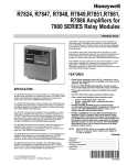
1
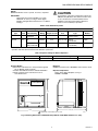
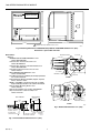
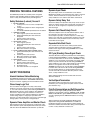
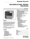
7800 SERIES
RM7824A Relay Module
PRODUCT DATA
•
•
•
•
•
•
•
•
•
•
GENERAL
The Honeywell RM7824A Relay Module is a 24 Vdc
microprocessor-based integrated burner control for
automatically fired gas, oil or combination fuel single burner
applications. The RM7824A consists of the Relay Module,
Subbase and Amplifier are required to complete the system.
Options include Keyboard Display Module, Personal Computer
Interface, DATA CONTROL BUS MODULE™, Remote Display
Module and COMBUSTION SYSTEM MANAGER™ Software.
The RM7824A is programmed to provide a level of safety,
functional capability and features beyond the capacity of
conventional controls.
Functions provided by the RM7824A include automatic burner
sequencing, flame supervision, system status indication,
system or self-diagnostics and troubleshooting.
FEATURES
•
•
•
•
•
Safety features:
—
Closed loop logic test.
—
Dynamic input check.
—
Dynamic safety relay check.
—
Dynamic self-check logic.
—
Expanded safe-start check.
—
Internal hardware status monitoring.
—
Tamper resistant timing and logic.
Access for external electrical voltage checks.
Application flexibility.
Communications interface capability.
Dependable, long-term operation provided by
microcomputer technology.
Copyright © 1995 Honeywell Inc. • All Rights Reserved
First-out annunciation and system diagnostics are provided
by a 2-row by 20-column Vacuum Fluorescent Display
(VFD) located on the optional Keyboard Display Module.
Five light emitting diodes (LEDs) for sequence
information.
Flame signal strength.
Local or remote annunciation of RM7824A operation and
fault information (optional).
Nonvolatile memory; RM7824A retains history files and
sequencing status after loss of power.
Plug-in flame amplifier.
Remote reset (optional).
Report generation (optional).
Shutter drive output.
Burner controller data (optional):
—
Hold status.
—
Lockout/alarm status.
—
Sequence status.
—
Sequence time.
—
Total cycles of operation.
—
Total hours of operation.
—
Fault history providing the six most recent faults:
– Cycles of operation at the time of the fault.
– Fault message and code.
– Hours of operation at the time of the fault.
– Sequence status at the time of the fault.
– Sequence time at the time of the fault.
—
Diagnostic information:
– Device type.
– Flame amplifier type.
– Flame failure response time.
– Manufacturing code.
– On/Off status of all digital inputs and outputs.
– Software revision and version of RM7824A and
optional Keyboard Display Module.
– Status of configuration jumper.
Contents
General ...............................................................................
Features ..............................................................................
Specifications ......................................................................
Ordering Information ...........................................................
Principal Technical Features ...............................................
Safety Provisions ................................................................
Installation ...........................................................................
Wiring ..................................................................................
Assembly .............................................................................
Operation ............................................................................
Static Checkout ...................................................................
Checkout .............................................................................
Troubleshooting ...................................................................
1
1
2
2
5
5
6
7
9
10
12
13
18
65-0155-1
7800 SERIES RM7824A RELAY MODULE
SPECIFICATIONS
Environmental Ratings:
Ambient Temperature:
Operating: -40°F to +140°F (-40°C to +50°C).
Storage: -60°F to +150°F (-49°C to +66°C).
Humidity: 85% relative humidity, noncondensing.
Vibration: 0.5G environment.
Model:
RM7824A Relay Module for the 7800 SERIES.
Electrical Ratings (See Table 1):
Voltage: 24 Vdc (22-28 Vdc).
Power Dissipation: 10W maximum.
Maximum Total Connected Load: 500 VA.
Fusing: Total Connected Load: 20A maximum, type FRN or
equivalent.
Dimensions:
See Fig. 1 through 4.
Table 1. Terminal Ratings.
Terminal No.
G
L2(N)
Ratings
Flame Sensor Ground
24 Vdc Common (-)
3
24 Vdc Supply (+)
24 Vdc (22 to 28 Vdc). 1
4
Alarm
24 Vdc, 1A, 5A Inrush for 6000 cycles.
5
Unused
6
Burner Controller and Limits
7
Unused
8
Pilot Valve/Ignition
24 Vdc, 5A Inrush, 1A Continuous.
9
Main Fuel Valve
24 Vdc, 10A Inrush, 2A Continuous or 50 VA motorized valve.
10
Ignition
24 Vdc, 5A Inrush, 1A Continuous.
F(11)
1
Description
24 Vdc, 20 mA.
Flame Sensor
12
Unused
13
Unused
14
Unused
15
Unused
16
Unused
17
Unused
18
Unused
19
Unused
20
Unused
21
Unused
22
Shutter
500 VA maximum connected load to RM7824A assembly.
24 Vdc, 0.5A.
ORDERING INFORMATION
When purchasing replacement and modernization products from your 7800 SERIES distributor, refer to the TRADELINE®
Catalog or price sheets for complete ordering number.
If you have additional questions, need further information, or would like to comment on our products or services, please write or
phone:
1. Your local Honeywell Home and Building Control Sales Office (check white pages of phone directory).
2. Home and Building Control Customer Logistics
Honeywell Inc., 1885 Douglas Drive North
Minneapolis, Minnesota 55422-4386
In Canada—Honeywell Limited/Honeywell Limitée, 35 Dynamic Drive, Scarborough, Ontario M1V 4Z9. International Sales and
Service Offices in all principal cities of the world. Manufacturing in Australia, Canada, Finland, France, Germany, Japan, Mexico,
Netherlands, Spain, Taiwan, United Kingdom, U.S.A.
65-0155—1
2
7800 SERIES RM7824A RELAY MODULE
Weight:
RM7824A with Dust Cover: 1 pound, 12 ounces, unpacked.
CAUTION
To prevent the control from sequencing on power up,
RM7824 Relay Modules with software revision 2424
or less should not be used with R7848 Infrared
Amplifiers and C7015 Infrared Flame Detectors,
unless a ten-second delay is provided.
IMPORTANT
Flame Detection System available for use with
RM7824A. To select your Plug-in Flame Signal
Amplifier and applicable Flame Detector, see Table 2
and Fig. 3.
Table 2. Flame Detection Systems.
Plug-in Flame Signal Amplifiers
Type
Color
Self-Checking
Rectification
Green
Dynamic
Self-Check
Infrared
Red
a
Applicable Flame Detectors
Flame Failure
Response Time
Model
a
Fuel
Type
Models
R7824C
3 sec
Gas, oil, coal Ultraviolet
(Purple Peeper)
C7024E,F
No
R7848A
3 sec
Gas, oil, coal Infrared
(Lead Sulfide)
C7015.
Dynamic
AMPLI-CHECK®
R7848B
3 sec
Gas, oil, coal Infrared
(Lead Sulfide)
C7015.
Circuitry tests all electronic components in the flame detection system (amplifier and detector) 12 times a minute during burner
operation and shuts down the burner if the detection system fails.
Table 3. Sequence Timing For Normal Operation.
Device
Initiate
Standby
RM7824A
10 sec
* STANDBY and RUN can be an infinite time period.
*
Pilot Flame Establishing Period
Run
4 or 10 sec
*
Mounting:
Q7800A for panel mount or Q7800B for wall or burner mount.
Approval Bodies:
Underwriters Laboratories Inc. Component Recognized:
File no. MP268, guide no. MCCZ.
Canadian Standards Association certified: LR9S329-3.
Federal Communications Commission: Part 15,
Class B-Emissions.
Required Components:
Plug-in Flame Signal Amplifier; see Fig. 2.
Q7800A or Q7800B.
BURNER CONTROL
5
(127)
1
5-1/4 (133)
5 (127)
1
REMOVE ONLY FOR TERMINAL TEST ACCESS.
M5872
Fig. 1. Mounting dimensions of RM7824A Relay Module and Q7800A Subbase in in. (mm).
3
65-0155—1
7800 SERIES RM7824A RELAY MODULE
BURNER CONTROL
5
(127)
1
6-3/32 (155)
5 (127)
1
REMOVE ONLY FOR TERMINAL TEST ACCESS.
M5873
Fig. 2. Mounting dimensions of RM7824A Relay Module and Q7800B Subbase in in. (mm).
Dust Cover is part number 221729A.
Accessories:
Optional:
COMBUSTION SYSTEM MANAGER™: Part
number ZM7850A1001.
Communication Interface Base Unit: Part
number Q7700A1014.
Communication Interface ControlBus Module: Part
number QS7800A1001.
ControlBus 5-Wire Electrical Connector: Part
number 203541.
DATA CONTROLBUS MODULE™: Part
number S7810A1009.
Flush Mounting Kit for S7800 Keyboard Display Module:
Part number 205321B.
Keyboard Display Module (S7800A): English, Spanish,
French, German, Italian.
NEMA 4 and NEMA 1 Weatherproofing Kit for S7800
Keyboard Display Module: Part number 204718A,B.
Remote Display Mounting Bracket: Part
number 203765.
Remote Reset Module: Part number S7820A1007.
Sixty-inch Extension Cable Assembly: Part
number 221818A.
CELL MOUNT
5-1/8
(130)
3-3/4
(95)
3-7/16
(87)
1/2–14 NPSM
5-1/4 (133)
LEADWIRES
FACEPLATE
C7024E
1–11-1/2 NPT
FACEPLATE
PIPE
UNION
1(25)
8
(203)
DIA.
5
(127)
1/2–14 NPT
HEAT BLOCK
1-1/2
(38)
LEADWIRES
2-1/16
(52)
2(51)
1-5/8 (41)
2-3/4
(70)
3/4–14 NPT
MOUNTING FLANGE
7-7/32 (183)
9 (229)
3 (76)
1-1/16 (27)
2
(51)
5/16–18 UNC–2B BY
7/16 [11] DEEP
MOUNTING HOLES (2)
C7024F
1-1/4
(32)
2 LEADS IN A
48 INCH (1.2 METER)
FLEXIBLE CONDUIT
BUSHING WITH
MAGNIFYING LENS
M5818
1-1/4
(32)
Fig. 4. Rectification detectors in in. (mm).
APERTURE
3/4-14
NPSM
COLLAR, 3/4-14 NPSM
INTERNAL THREADS
3/4-14 NPSM
INTERNAL
THREADS
M1982A
Fig. 3. Infrared detector dimensions in in. (mm).
65-0155—1
4
7800 SERIES RM7824A RELAY MODULE
PRINCIPAL TECHNICAL FEATURES
Dynamic Input Check
The RM7824A provides all customary flame safeguard
functions while providing significant advancements in the
areas of safety, annunciation and system diagnostics.
All system input circuits are examined to assure that the
RM7824A is capable of recognizing the true status of external
controls, limits and interlocks. If any input fails this test, a
safety shutdown occurs and the fault will be annunciated.
Safety Shutdown (Lockout) Occurs If:
Dynamic Safety Relay Test
Checks the ability of the dynamic safety relay contact to open
and close. Verifies that the safety critical loads, terminals 8, 9
and 10, can be de-energized, as required, by the Dynamic
Self-check logic.
1. INITIATE PERIOD.
a. 24 Vdc power errors occurred, see Operation
section.
b. Configuration jumper has been changed (after
200 hours).
c. Four minute INITIATE period has been exceeded.
2. STANDBY PERIOD.
a. Flame signal is present after 40 seconds.
b. Ignition/intermittent pilot valve terminal is
energized.
c. Internal system fault occurred.
d. Main valve terminal is energized.
3. SAFE START CHECK.
a. Flame signal is present.
b. Ignition/intermittent pilot valve terminal is
energized.
c. Internal system fault occurred.
d. Main valve terminal is energized.
4. PILOT FLAME ESTABLISHING PERIOD (PFEP).
a. Ignition/intermittent pilot valve terminal is not
energized.
b. Internal system fault occurred.
c. Main valve terminal is energized.
d. No flame present at end of PFEP.
5. RUN PERIOD.
a. Ignition terminal is energized.
b. Internal system fault occurred.
c. Main valve terminal is not energized.
d. No flame present.
e. Pilot valve terminal is not energized.
Dynamic Self-Check Safety Circuit
The microcomputer tests itself and related hardware, and at
the same time, the safety relay system tests the
microcomputer operation. If a microcomputer or safety relay
failure occurs and does not allow proper execution of the selfcheck routine, safety shutdown occurs and all safety critical
loads will be de-energized.
Expanded Safe-Start Check
The conventional safe-start check, which prevents burner
start-up if flame is indicated at start-up, is expanded to
include a flame signal check during STANDBY and a safety
critical load check.
Off Cycle (Standby) Flame Signal Check
SAFETY PROVISIONS
The flame detection subsystem (flame detector and amplifier)
is monitored during STANDBY. If a flame simulating condition
or an actual flame exists for 40 seconds in STANDBY, a safety
shutdown occurs and startup is prevented. If the flame signal
exists at any time after the 40 seconds during STANDBY, a
safety shutdown occurs and is annunciated. The self-checking
detector is energized for the first 40 seconds during
STANDBY and the last two seconds before exiting STANDBY.
If a flame exists after the first 40 seconds during STANDBY,
the self-checking detector is energized during the last ten
seconds of the 40 second flame detection period. If a flame
exists, a safety shutdown occurs.
Internal Hardware Status Monitoring
Safety and logic timings are inaccessible and cannot be
altered or defeated.
The RM7824A analyzes the integrity of the configuration
jumper and internal hardware. The POWER LED will blink
every four seconds, signifying an internal hardware check.
Verified Spark Termination
The ignition terminal is monitored to assure early spark
termination (ten seconds ignition and pilot and ten seconds
pilot and main only).
Closed Loop Logic Test
The test verifies the integrity of all safety critical loads,
terminals 8, 9 and 10. If the loads are not energized properly;
i.e., the main valve terminal is powered during STANDBY, the
RM7824A will lockout on safety shutdown. The RM7824A
must react to input changes but avoid the occurrence of
nuisance shutdown events. Signal conditioning is applied to
24 Vdc voltage inputs to verify proper operation in the
presence of normal electrical line noise such as transient high
voltage spikes or short periods of voltage dropout.
First-Out Annunciation and Self-Diagnostics
Sequence Status Lights (LEDs) provide positive visual
indication of the program sequence: POWER, PILOT, FLAME,
MAIN and ALARM. The green POWER LED blinks every four
seconds, signifying that the RM7824A hardware is running
correctly.
Optional multi-function Keyboard Display Module shows
elapsed time during PILOT IGNITION. As an additional
troubleshooting aid, it provides sequence timing, diagnostic
information and historical information during normal operation
or when a safety shutdown or hold occurs.
Dynamic Flame Amplifier and Shutter Check
Self-checking circuitry tests all electronic components in the
flame detection system and amplifier twelve times per minute
and shuts down the RM7824A if the detection system fails.
5
65-0155—1
7800 SERIES RM7824A RELAY MODULE
First-out Annunciation reports the cause of a safety shutdown
or identifies the cause of a failure to start or continue the
burner control sequence with an English text and numbered
code via the optional Keyboard Display Module. It monitors all
field input circuits, including the flame signal amplifier. The
system distinguishes 39 modes of failure and detects and
annunciates difficult-to-find intermittent failures.
7. All external timers must be listed or component
recognized by authorities who have jurisdiction for the
specific purpose for which they are used.
IMPORTANT
1. For on-off gas-fired systems, some authorities who
have jurisdiction prohibit the wiring of any limit or
operating contacts in series between the flame
safeguard control and the main fuel valve(s).
2. Two C7024E,F Detectors can be connected in
parallel.
3. This equipment generates, uses and can radiate
radio frequency energy, and if not installed and
used in accordance with the instructions, may
cause interference to radio communications. It has
been tested and found to comply with the limits for
a Class B computing device of part 15 of FCC
rules, which are designed to provide reasonable
protection against such interference when
operated in a commercial environment. Operation
of this equipment in a residential area may cause
interference, in which case the users, at their own
expense, may be required to take whatever
measures are required to correct this interference.
4. This digital apparatus does not exceed the Class
B limits for radio noise of digital apparatus set out
in the Radio Interference Regulations of the
Canadian Department of Communications.
Self-diagnostics add to the First-out Annunciation by allowing
the RM7824A to distinguish between field (external device)
and internal (system related) problems. Faults associated
within the flame detection subsystem or RM7824A are
isolated and reported by the optional Keyboard Display
Module. See the 7800 SERIES System Annunciation
Diagnostics and Troubleshooting, form 65-0118.
INSTALLATION
WARNING
FIRE OR EXPLOSION HAZARD CAN CAUSE
PROPERTY DAMAGE, SEVERE INJURY, OR
DEATH.
To prevent possible hazardous burner operation,
perform verification of safety requirements each time
a control is installed on a burner.
When Installing this Product...
Humidity
1. Read these instructions carefully. Failure to follow them
could damage the product or cause a hazardous
condition.
2. Check the ratings given in the instructions and marked
on the product to make sure the product is suitable for
your application.
3. Installer must be a trained, experienced, flame
safeguard service technician.
4. After installation is complete, check out the product
operation as provided in these instructions.
Install the RM7824A where the relative humidity never
reaches the saturation point. The RM7824A is designed to
operate in a maximum 85 percent relative humidity,
continuous, noncondensing moisture environment.
Condensing moisture can cause a shutdown.
Vibration
Do not install the RM7824A where it could be subjected to
vibration in excess of 0.5G continuous maximum vibration.
Weather
CAUTION
The RM7824A is not designed to be weather tight. If installed
outdoors, the RM7824A must be protected by an approved
weather-tight enclosure.
To prevent electrical shock and equipment damage,
disconnect the power supply before beginning
installation. More than one power supply disconnect
may be involved.
Mounting Wiring Subbase
1. To prevent electrical shock and equipment damage,
disconnect the power supply before beginning
installation. More than one power supply disconnect
may be involved.
2. Wiring connections for the RM7824A are unique;
therefore, refer to Fig. 6 or the correct specifications for
proper subbase wiring.
3. Wiring must comply with all applicable codes,
ordinances and regulations.
4. Wiring, where required, must comply with NEC Class 1
wiring.
5. Loads connected to the RM7824A must not exceed
those listed on the RM7824A label or the specifications
(see Table 1).
6. Limits and interlocks must be rated to carry and break
current simultaneously to the ignition transformer, pilot
valve, and main fuel valve(s).
65-0155—1
NOTE:
For installation dimensions, see Fig. 1 or 2.
1. Mount the subbase in any position except horizontally
with the bifurcated contacts pointing down. The standard
vertical position is recommended. Any other position
decreases the maximum ambient temperature rating.
2. Select a location on a wall, burner or in an electrical
panel. The Q7800 can be mounted directly in the
control cabinet. Be sure to allow adequate clearance for
servicing, installation, access and removal of the
RM7824A, dust cover, flame amplifier, flame amplifier
signal voltage probes, electrical signal voltage probes
and electrical field connections.
3. For surface mounting, use the back of the subbase as a
template to mark the four screw locations. Drill the pilot
holes.
4. Mount the subbase securely using four No. 6 screws.
6
7800 SERIES RM7824A RELAY MODULE
WIRING
1.
b.
The maximum number of wires per terminal is
two. If more than two wires need to be connected
to a terminal, wire one of the wires to the terminal
and use a wire nut to connect the other wires
inside the subbase.
5. Recommended wire routing for flame detector
leadwires:
•
Do not run high voltage ignition transformer wires
in the same conduit with the flame detection
wiring.
•
Do not route scanner wires in a conduit with line
voltage circuits.
•
Enclose scanner wires without armor cable in
metal cable or conduit.
•
Follow directions given in the flame detector
instructions.
6. Maximum wire lengths:
a. For the RM7824A, the maximum length of
leadwire to the control terminal input is 300 feet.
b. For the flame detector leadwires, the maximum
flame sensor leadwire length is limited by the
flame signal strength.
a.
For the internal block diagram of the RM7824A,
see Fig. 5.
b. For proper subbase wiring, refer to Fig. 6.
c. For proper remote wiring of the Keyboard Display
Module; refer to the Specifications for the
Keyboard Display Module (65-0090),
Communication Interface Base Unit (63-2278),
DATA CONTROLBUS MODULE™ (65-0091), or
Extension Cable Assembly (65-0131).
2. Disconnect the power supply from the main disconnect
before beginning installation to prevent electrical shock
and equipment damage. More than one disconnect may
be involved.
3. All wiring must comply with all appropriate electrical
codes, ordinances and regulations. Wiring, where
required, must comply with NEC Class 1 wiring.
4. a. Recommended wire size and type: Use No. 14, 16,
or 18 copper conductor (TTW60C or THW75C or
THHN90C) 600 volt insulation wire for all low
voltage terminals. For high temperature
installations, use wire selected for a temperature
rating above the maximum operating temperature.
All leadwires must be moisture resistant.
+
–
1
3
L2
24 VDC
CONFIGURATION
JUMPERS
TEST
JACK
FLAME SIGNAL
F
MICROCOMPUTER
TEST
RESET
PUSHBUTTON
PLUG-IN
FLAME
AMPLIFIER
G
22
2K
RELAY
DRIVE
CIRCUIT
SAFETY RELAY
CIRCUIT
3K
RELAY
STATUS
FEEDBACK
AND LINE
VOLTAGE
INPUTS
4K
1K
STATUS LEDs
POWER SUPPLY
LIMITS CONTROLLER
1K1
4K1
CONTROL
POWER
2K1
6
10
IGNITION
8
PILOT
9
MAIN VALVE
4
ALARM
2K2
3K1
DDL
OPTIONAL KEYBOARD
DISPLAY MODULE
INDICATES FEEDBACK SENSING
TO RELAY STATUS FEEDBACK
AND LINE VOLT INPUTS
RS485
1
DDL
COMMUNICATIONS
1
2
3
FIELD WIRING
INTERNAL WIRING
REMOTE
RESET
PROVIDE DISCONNECT MEANS AND OVERLOAD PROTECTION AS REQUIRED.
M5821
Fig. 5. Internal block diagram of the RM7824A (see Fig. 6 for detailed wiring instructions).
7
65-0155—1
7800 SERIES RM7824A RELAY MODULE
9. Check all wiring circuits and complete the Static
Checkout section before installing the RM7824A on the
subbase; see Table 5.
10. Install all electrical connectors.
11. Restore power to the panel.
7. Make sure loads do not exceed the terminal ratings.
Refer to the label on the RM7824A or to the ratings in
the specifications; see Table 1.
8. Check the power supply circuit. The voltage tolerance
must match those of the RM7824A. A separate power
supply circuit may be required for the RM7824A with
the required disconnect means and overload protection
added.
Q7800
G
12
L2
13
3
14
4
15
5
16
6
17
7
18
8
19
MAIN FUEL
VALVE(S)
9
20
IGNITION
10
21
24 VDC ALARM
BURNER
CONTROLLER/LIMITS
INTERMITTENT
PILOT/IGNITION
BROWN C7015 INFRARED
(LEAD SULFIDE)
DETECTOR
F
WHITE
3
2
22
+
OR
YELLOW C7024E,F
ULTRAVIOLET
FLAME DETECTOR
–
MASTER
SWITCH
BLUE
24 VDC
1
WHITE
WHITE
RED
BLACK
L2
3
L2
1 24 VDC POWER SUPPLY. PROVIDE DISCONNECT MEANS AND OVERLOAD PROTECTION AS REQUIRED.
2 DO NOT CONNECT ANY WIRES TO UNUSED TERMINALS.
3 FOR A CONTINUOUS OR STANDING PILOT, INSTALL AN EXTERNAL RELAY TO SWITCH THE F LEAD. THE
RELAY MUST HAVE GOLD-CLAD OR GOLD-FLASH CONTACTS AND A 120 VAC COIL. POWER THE RELAY
COIL FROM THE Q7800 SUBBASE TERMINAL 8. CONNECT THE RELAY CONTACTS BETWEEN THE F LEAD OF
THE DETECTOR AND THE F TERMINAL OF THE Q7800 SUBBASE. A 24 VDC RELAY IS ACCEPTABLE TO
USE IN THIS TYPE OF APPLICATION. USE THE N.O. PILOT DUTY CONTACTS.
M5820A
Fig. 6. Wiring the RM7824A.
65-0155—1
8
7800 SERIES RM7824A RELAY MODULE
ASSEMBLY
Mounting RM7824A
NOTE:
For installation dimensions, see Fig. 1 or 2.
Relay Module Mounting
1. Mount the RM7824A vertically, see Figs. 7 or 8, or
mount horizontally with the knife blade terminals
pointing downward. When mounted on the Q7800A, the
RM7824A must be in an electrical enclosure.
2. Select the location in the electrical enclosure. Be sure to
allow adequate clearance for servicing, installation and
removal of the RM7824A, dust cover, flame amplifier,
flame amplifier signal voltage probes, electrical signal
voltage probes and electrical connections.
a. Allow an additional two inches below the
RM7824A for the flame amplifier mounting.
b. Allow an optional three-inch minimum to both
sides of the RM7824A for electrical signal voltage
probes.
3. Make sure no subbase wiring is projecting beyond the
terminal blocks. Tuck in wiring against the back of the
subbase so it does not interfere with the knife blade
terminals or bifurcated contacts.
Fig. 8. Wall or burner installation.
Mounting Dust Cover
1. Align the two interlocking ears of the Dust Cover with
the two mating slots on the RM7824A (see Fig. 9).
2. Insert the two interlocking ears into the two mating
slots, and with a hinge action, push on the upper
corners of the Dust Cover to secure it to the RM7824A.
3. Be sure the Dust Cover is firmly in place.
IMPORTANT
The RM7824A must be installed with a plug-in
motion rather than a hinge action.
4. Mount the RM7824A by aligning the four L-shaped
corner guides and knife blade terminals with the
bifurcated contacts on the wiring subbase and securely
tightening the two screws. Do not tighten the screws to
the point where they deform the plastic of the RM7824A
case.
Fig. 9. Dust Cover mounting.
Installing Plug-In Flame Signal Amplifier
1. Disconnect the power supply before beginning
installation to prevent electrical shock and equipment
damage. More than one disconnect may be involved.
2. Align the amplifier circuit board edge connector with the
keyed receptacle on the RM7824A. Verify that the
amplifier nameplate faces away from the Relay Module
(see Fig. 10).
3. Push in the amplifier until the circuit board is fully
inserted into the receptacle and then push the amplifier
toward the RM7824A retaining clasp.
4. Verify the amplifier is firmly in place.
5. Perform all required checkout tests.
Fig. 7. Electrical panel installation.
9
65-0155—1
7800 SERIES RM7824A RELAY MODULE
INFRARED (C7015)
F
G
WHITE
BROWN
SOLID STATE SELF-CHECKING
ULTRAVIOLET (C7024E,F - E SHOWN)
Fig. 10. Flame signal amplifier mounting.
Installing Flame Detector
NOTE:
Table 2 and Fig. 11 list the flame detectors available
for use with the RM7824A. Make sure the correct
combination of amplifier and flame detector(s) is used.
BLUE
YELLOW
WHITE
F
G
22
1
WHITE
RED
24Vdc (–)
3
24Vdc (–)
Proper flame detector installation is the basis of a safe and
reliable flame safeguard installation. Refer to the instructions
packed with the flame detector and the equipment
manufacturer instructions.
1
BLACK
FLAME DETECTOR LEADS ARE COLOR CODED. THE BLUE LEAD
MUST BE CONNECTED TO THE F TERMINAL AND THE YELLOW
MUST BE CONNECTED TO THE G TERMINAL. THE UV SENSING
TUBE IS POLARITY SENSITIVE. REVERSING THE LEADS EVEN
MOMENTARILY CAN DAMAGE OR DESTROY THE UV TUBE.
M7594
Keep the flame signal leadwires as short as possible from the
flame detector to the wiring subbase. Capacitance increases
with wire length, reducing the signal strength. The maximum
permissible leadwire length depends on the type of flame
detector, leadwire and conduit. The ultimate limiting factor in
the flame detector leadwire is the flame signal (see Table 6).
Fig. 11. Flame detector wiring.
OPERATION
Sequence of Operation
The RM7824A has the following operation sequence (see Figs. 12 and 14).
00
INITIATE
POWER
STANDBY
POWER
SAFESTART
POWER
LED
DISPLAY
00
10
PFEP 2
4 OR 10 SEC RUN
POWER
POWER
PILOT
PILOT
FLAME
FLAME
MAIN
MAIN
ALARM
ALARM
IGNITION
BURNER
START
FLAME
SIGNAL
POWER
10
INTERMITTENT PILOT
OPERATING
CONTROLLER
AND LIMITS
STANDBY
MAIN VALVE
8
9
1
LIMITS AND BURNER CONTROL CLOSED + TO 6
SAFE START CHECK
FLAME PROVING
SSC
1 MAIN FUEL VALVE WILL BE ENERGIZED DURING PFEP IF FLAME IS PROVEN.
2 RM7890A1031 PFEP IS FIXED 30 SECOND.
Fig. 12. RM7824A sequence.
65-0155—1
10
M5135B
7800 SERIES RM7824A RELAY MODULE
CAPTIVE
MOUNTING
SCREW
Initiate
The RM7824A enters the INITIATE sequence if the Relay
Module verifies voltage fluctuations of outside 22 to 28 Vdc
during any part of the operating sequence. The INITIATE
sequence lasts for ten seconds unless the voltage tolerance
is not met. When the tolerance is not met, a hold condition will
be initiated and will be displayed on the optional Keyboard
Display Module for at least five seconds. When the tolerance
is met, the INITIATE sequence will restart. If the condition is
not corrected and the hold condition exists for four minutes,
the RM7824A will lock out. Causes for hold conditions in the
INITIATE sequence are:
DUST
COVER
RELAY
MODULE
FLAME
AMPLIFIER
RESET
PUSHBUTTON
FLAME
SEQUENCE
SIMULATOR INPUT
STATUS LEDS
• Vdc dropout is detected.
• Internal timing functions are not synchronized.
• The noise that can prevent a sufficient reading of the low
voltage inputs.
• Brownouts caused by low input voltage.
FLAME CURRENT
TEST JACK
M7593
Fig. 13. Sequence status LEDs.
INITIATE
STANDBY
STANDBY
HOLD: F/G
(FLAME
DETECTED)
PILOT
IGNITION
RESET/
ALARM
TEST
RUN
POWER
POWER
POWER
PILOT
PILOT
PILOT
PILOT
PILOT
FLAME
FLAME
FLAME
FLAME
FLAME
POWER
POWER
PILOT
PILOT
FLAME
FLAME
POWER
SAFESTART
CHECK
MAIN
MAIN
MAIN
ALARM
ALARM
ALARM
MAIN
ALARM
POWER
MAIN
MAIN
MAIN
ALARM
ALARM
ALARM
M3362
Fig. 14. LED sequence status display information (see Fig. 13).
Standby
Selectable Site-Configurable Jumper
The RM7824A is ready to start an operating sequence when
the operating control input determines a call for heat is present.
The burner switch, limits, operating limit control and all
microcomputer monitored circuits must be in the correct state
for the RM7824A to continue into the SAFE-START CHECK.
The RM7824A has one site-configurable jumper option, see
Fig. 15 and Table 4. The site-configurable jumper should be
clipped with side cutters and the resistor removed from the
Relay Module.
SELECTABLE CONFIGURATION JUMPER
Normal Start-Up Safe-Start Check
The RM7824A verifies that a flame does not exist and
proceeds into the ignition trial. If a flame is present, the
RM7824A will recycle to the STANDBY period. If the critical
loads are not in the correct state, a safety shutdown occurs.
Ignition Trials
Pilot Flame Establishing Period (PFEP):
1. The pilot valve and ignition transformer, terminals 8 and
10, are energized. The RM7824A has an intermittent
pilot valve, terminal 8.
2. Flame must be proven by the end of the 4 or 10 second
PFEP to allow the sequence to continue. If flame is not
proven by the end of PFEP, a safety shutdown occurs.
3. With flame proven, the ignition, terminal 10, is deenergized and the main valve, terminal 9, is energized.
M7592
Fig. 15. Selectable site-configurable jumpers.
Run
The RM7824A is now in RUN and will remain in RUN until the
controller input, terminal 6, opens, indicating that the demand
is satisfied or a limit has opened.
11
65-0155—1
7800 SERIES RM7824A RELAY MODULE
Table 4. Site-Configurable Jumper Options.
Jumper
Number
JR1
Equipment Recommended
Description
Intact
Clipped
Pilot Flame
Establishing Period
10 seconds
4 seconds
1. Voltmeter (20K ohm/volt minimum sensitivity) set on the
0-30 Vdc scale.
2. Two jumper wires: No. 14 wire, insulated, 12 in. (305 mm)
long, with insulated alligator clips at both ends.
General Instructions
IMPORTANT
After 200 hours of operation, the configuration
jumper cannot be changed. If it is changed after
200 hours of operation, the RM7824A locks out. The
RM7824A cannot be reset and has to be replaced.
SERVICE NOTE:
1. Perform all applicable tests listed in Static Checkout,
Table 5, in the order listed.
2. MAKE SURE THAT ALL MANUAL FUEL SHUTOFF
VALVE(S) ARE CLOSED.
3. Perform only those tests designated for the specific
RM7824A model being tested.
4. Raise the set point of the operating controller to
simulate a call for heat.
5. For each test, open the master switch and install the
jumper wire(s) between the subbase wiring terminals
listed in the Test Jumpers column of Table 5.
6. Close the master switch before observing operation.
7. Read the voltage between the subbase wiring terminals
listed in the Voltmeter column of Table 5.
8. If there is no voltage or the operation is abnormal,
check the circuits and external devices as described in
the last column.
9. Check all wiring for correct connections, tight terminal
screws, correct wire, and proper wiring techniques.
Replace all damaged or incorrectly sized wires.
10. Replace faulty controllers, limits, interlocks, actuators,
valves, transformers, motors and other devices as
required.
11. Obtain normal operation for each required test before
continuing the checkout.
12. After completing each test, be sure to remove the test
jumper(s).
Clipping and removing a site-configurable
jumper enhances the level of safety.
STATIC CHECKOUT
CAUTION
1. Use extreme care while testing the system. Voltage
is present on most terminal connections when
power is on.
2. Open the master switch before installing or
removing a jumper on the subbase.
3. Before continuing to the next test, be sure to
remove the test jumper(s) used in the previous
tests.
4. Replace all limits and interlocks not operating
properly. Do not bypass limits and interlocks.
5. Close all manual fuel shutoff valve(s) before
starting these tests.
Table 5. Static Checkout.
Test No.
RM7824A
Models
Test
Jumpers
Voltmeter
Normal Operation
If Operation is Abnormal, Check
the Item Listed Below
WARNING
Make sure all manual fuel shutoff valves are closed.
IMPORTANT
Low fuel pressure limits, if used, could be open. Bypass them with jumpers for the remaining Static tests (if required).
1
All
None
3-L2
24 Vdc at terminal 3
1. Master switch.
2. Power connected to the master
switch.
3. Overload protection (fuse,
circuit breaker) has not opened
the power line.
2
All
None
6-L2
24 Vdc at terminal 6
1. Limits.
2. Burner controller.
3
All
3-10
—
Ignition spark (if ignition
transformer relay is
connected to terminal 10).
1. Watch for spark or listen for
buzz.
a. Ignition electrodes are clean.
b. Ignition transformer is okay.
(Continued)
65-0155—1
12
7800 SERIES RM7824A RELAY MODULE
Table 5. Static Checkout (Continued).
Test No.
RM7824A
Models
Test
Jumpers
Voltmeter
Normal Operation
4
All
3-8
—
1. Ignition spark (if ignition
transformer relay is
connected to terminal 8).
2. Automatic pilot valve
opens (if connected to
terminal 8).
5
All
3-9
—
NOTE: Refer to wiring
diagram of system
being tested.
Automatic fuel valve(s)
opens.
If using direct spark ignition,
check the first stage fuel
valve(s) instead of the pilot
valve.
6
All
Final
All
3-4
—
Alarm (if used) turns on.
If Operation is Abnormal, Check
the Item Listed Below
1. Watch for spark or listen for
buzz.
a. Ignition electrodes are clean.
b. Ignition transformer is okay.
2. Listen for click or feel head of
valve for activation.
a. Actuator if used.
b. Pilot valve.
Same as test no. 4. If using direct
spark ignition, check the first stage
fuel valve(s) instead of the pilot
valve.
1.
Alarm.
CAUTION
After completing these tests, open the master switch and remove all test jumpers
from the subbase terminals. Also remove bypass jumpers from the low fuel
pressure limits (if used).
CHECKOUT
WARNING
CAUTION
Do not allow fuel to accumulate in the combustion
chamber. If fuel is allowed to enter the chamber for
longer than a few seconds without igniting, an
explosive mixture could result. It is recommended that
you limit the trial for pilot to ten seconds, and limit the
attempt to light the main burner to two seconds from
the time the fuel has reached the burner nozzle. In
any case, do not exceed the nominal lightoff time
specified by the equipment manufacturer. Close the
manual shutoff valve(s) if the flame is not burning at
the end of the specified time.
If an RM7824A is replaced with a lower or higher
functioning 7800 SERIES Relay Module, the burner
will not sequence unless wiring changes are made.
IMPORTANT
1. If the system fails to perform properly, refer to
7800 SERIES System Annunciation Diagnostics
and Troubleshooting, form 65-0118.
2. Repeat ALL required Checkout tests after all
adjustments are made. ALL tests must be
satisfied with the flame detector(s) in its FINAL
position.
CAUTION
Equipment Required
1. Use extreme care while testing the system. Voltage
is present on most terminal connections when
power is on.
2. Open the master switch before removing or
installing the RM7824A.
3. Make sure all manual fuel shutoff valve(s) are
closed before starting the initial lightoff check and
the Pilot Turndown tests.
4. Do not put the system in service until you have
satisfactorily completed all applicable tests in this
section and any others required by the equipment
manufacturer.
Volt-ohmmeter (20K ohm/volt minimum sensitivity):
• 0-6000 ohm capability.
• 0-30 Vdc capability.
Checkout Summary
• Preliminary inspection—all installations.
• Flame signal measurement—all installations.
• Initial lightoff check for proved pilot—all installations using
a pilot.
• Initial lightoff check for direct spark ignition of oil—all
burners using DSI.
• Pilot turndown test—all installations using a pilot.
13
65-0155—1
7800 SERIES RM7824A RELAY MODULE
• Hot refractory hold-in test—all installations.
• Ignition spark pickup—all installations using Ultraviolet
Flame Detectors.
• Response to other ultraviolet sources—all installations
using Ultraviolet Flame Detectors.
• Flame signal with hot combustion chamber—all
installations.
• Safety shutdown tests—all installations.
2. Flame detector(s) is clean, installed and positioned
properly. Consult the applicable instructions.
3. Correct combination of amplifier and flame detector(s)
is used. See Table 2 in the Specifications section.
4. Plug-in amplifier is securely in place.
5. Burner is completely installed and ready to fire; consult
equipment manufacturer instructions. Fuel lines are
purged of air.
6. Combustion chamber and flues are clear of fuel and
fuel vapor.
7. Power is connected to the system disconnect switch
(master switch).
8. Lockout switch is reset (push in reset pushbutton) only
if the RM7824A is powered. See Fig. 1 and 2.
9. System is in the STANDBY condition. POWER LED is
energized.
10. All limits and interlocks are reset.
See Fig. 13 for location of component parts and see Fig. 6 or
Q7800 Specifications for terminal locations.
Preliminary Inspection
Perform the following inspections to avoid common problems.
Make certain that:
1. Wiring connections are correct and all terminal screws
are tight.
Table 6. Flame Signal (See Fig. 15).
Flame Detector
Flame Signal Amplifier
Minimum Acceptable
Steady dc Voltage a
Maximum Expected
dc Voltage
C7024E,F
R7824Cb
1.25 Vdc
C7015A
R7848A,Bc
5.0 Vdc at the Keyboard Display Module or
5.0 Vdc at a 20K ohm/volt voltmeter.
a
This minimum or a stronger signal should be easily obtained if the detector is correctly installed and positioned to properly
sense the flame. This voltage must be obtained before completing checkout.
b The flame signal amplifier circuitry is tested one-half second every five seconds during burner operation and shuts down the
burner if the amplifier fails (all installations).
c The amplifier is an AMPLI-CHECK™ type.
4. Allow a few seconds for the meter reading to stabilize.
5. When using a shutter check amplifier, read the average
stable voltage, disregarding the peaks and valleys
caused by the self-checking program.
6. The meter reading must be as specified in Table 6 after
all tests are completed and all adjustments are made.
Flame Signal Measurement
Measure the flame signal at the appropriate times defined in
the following checkout tests. Read the flame signal volts dc at
the flame amplifier test jacks (+) and (-) (Com).
1. Use a 20K ohm per volt voltmeter with a 0 to 30 Vdc
capability.
2. Set the voltmeter to the 0 to 10 Vdc range.
3. Insert the positive (red) probe into the (+) jack of the
flame amplifier and the negative (black) probe into the
( -) (Com) jack of the flame amplifier (see Fig. 16).
As an option, the flame signal can be checked by using the
optional Keyboard Display Module.
If the signal is unstable or less than the minimum acceptable
voltage, check the flame detector installation and circuitry.
1. Check the supply voltages at terminals 3 and L2 (N).
Make sure the master switch is closed, connections are
correct and the power supply voltage is correct.
2. Check the detector wiring for defects including:
•
Deteriorated wire.
•
Incorrect connections.
•
Leakage paths caused by moisture, soot or
accumulated dirt.
•
Open circuits.
•
Short circuits.
•
Wrong wire type.
3. For all optical detectors, clean the detector viewing
window and inside the sight pipe as applicable.
4. With the burner running, check the temperature at the
detector. If it exceeds the detector maximum rated
temperature:
•
Add a heat block to stop conducted heat traveling
up the sight pipe.
•
Add a shield or screen to reflect radiated heat.
•
Add cooling (refer to sight pipe ventilation in the
detector instructions).
5. Make sure that the flame adjustment is not too lean.
POSITIVE (+)
METER LEAD
NEGATIVE (-)
METER LEAD
ONE
MEGOHM/VOLT
METER
M7382
Fig. 16. Flame signal measurement.
65-0155—1
14
7800 SERIES RM7824A RELAY MODULE
7. When the pilot ignites, measure the flame signal. If the
pilot flame signal is unsteady or approaching the 1.25 Vdc
minimum value, adjust the pilot flame size or detector
sighting to provide a maximum and steady flame signal.
8. Recycle the system to recheck lightoff and pilot flame
signal.
9. When the RUN period is displayed by the MAIN LED,
make sure the automatic main fuel valve is open; then
smoothly open the manual main fuel shutoff valve(s)
and watch for main burner flame ignition. When the
main burner flame is established, proceed to step 16.
10. If the main burner flame is not established within five
seconds or the normal lightoff time specified by the
equipment manufacturer, close the manual main fuel
shutoff valve(s).
11. Recycle the system to recheck lightoff and pilot flame
signal.
12. Let the RM7824A recycle to the RUN period. Smoothly
open the manual fuel shutoff valve(s) and try lightoff
again. (The first attempt may have been required to
purge the lines and bring sufficient fuel to the burner.)
13. If the main burner flame is not established within five
seconds or the normal lightoff time specified by the
equipment manufacturer, close the manual main fuel
shutoff valve(s). Check all burner adjustments.
14. If the main burner flame is not established after two
attempts:
a. Check for improper pilot size.
b. Check for excess combustion air.
c. Check for inadequate fuel flow.
d. Check for proper gas supply pressure.
e. Check for proper valve operation.
f. Check for proper pilot flame positioning.
15. Repeat steps 10 through 14 to establish the main
burner flame, then proceed to step 16.
16. With the sequence in RUN, make burner adjustments
for flame stability and Btu input rating.
17. Shut down the system by opening the burner switch or
by lowering the setpoint of the operating controller.
Make sure the main flame goes out. There may be a
delay due to gas trapped between the valve(s) and the
burner. Make sure the automatic fuel valve(s) closes.
18. Restart the system by closing the burner switch and/or
raising the setpoint of the operating controller. Observe
that the pilot is established during PILOT IGNITION and
the main burner flame is established during RUN within
the normal lightoff time.
19. Measure the flame signal. Continue to check for the
proper signal, see Table 6, through the RUN period.
20. Run the burner through another sequence, observing
the flame signal for:
a. Pilot flame alone (unless using direct spark
ignition).
b. Pilot and main flame together.
c. Main flame alone (unless monitoring an
intermittent pilot).
6. Make sure that the detector is properly sighting the
flame.
7. If necessary, resight or reposition the detector.
Initial Lightoff Check for Proved Pilot.
Perform this check on all installations that use a pilot. It
should immediately follow the preliminary inspection.
NOTE:
Low fuel pressure limits, if used, could be open. If so,
bypass them with jumpers during this check.
1. Open the master switch.
2. Make sure that the manual main fuel shutoff valve(s) is
closed. Open the manual pilot shutoff valve. If the pilot
takeoff is downstream from the manual main fuel
shutoff valve(s), slightly open the manual main valve to
supply pilot gas flow. Make sure the main fuel is shut off
just upstream from the burner inlet, or disconnect power
from the automatic main fuel valve(s).
3. Close the master switch and start the system with a call
for heat by raising the setpoint of the operating
controller (see Fig. 12 or RM7824A sequence). The
primary sequence should start the SAFE-START
CHECK sequence.
4. Let the sequence advance through STANDBY and
SAFE-START CHECK. Ignition spark should occur and
the pilot should light. If the pilot ignites, the FLAME LED
will be energized. Proceed to step 7.
5. If the pilot flame is not established in four or ten
seconds, safety shutdown occurs. Let the sequence
complete its cycle. Consult the equipment operating
manual for further information.
6. Push the reset pushbutton and let the system recycle
once. If the pilot still does not ignite, make the following
ignition/pilot adjustments:
a. Open the master switch and remove the
RM7824A from the subbase.
b. On the subbase, jumper terminal 3 to ignition
terminal 8 or 10; refer to the appropriate subbase
wiring diagram to determine the proper terminal.
Disconnect the leadwire to the pilot valve if it is
connected to the same terminal.
c. Close the master switch to energize only the
ignition transformer.
d. If the ignition spark is not strong and continuous,
open the master switch and adjust the ignition
electrode spark gap setting to the manufacturer
recommendation.
e. Make sure the ignition electrodes are clean.
f. Close the master switch and observe the spark.
g. After a continuous spark is obtained, open the
master switch and add a jumper on the subbase
from terminal 3 to the pilot terminal 8. Reconnect
the leadwire from the pilot valve if it was
disconnected in step b.
h. Close the master switch to energize both the
ignition transformer and the pilot valve.
i.
If the pilot does not ignite and if the ignition spark
is still continuous, adjust the pressure regulator
until a pilot is established.
j.
When the pilot ignites properly and stays ignited,
open the master switch and remove the jumper(s)
from terminals 3 to 8 or 3 to 10 of the subbase.
k. Check for adequate bleeding of the fuel line.
l.
Reinstall the RM7824A on the subbase and close
the master switch.
m. Return to step 4.
Also observe the time it takes to light the main flame. Ignition
of the main flame should be smooth.
21. Return the system to normal operation.
22. Make sure all readings are in the required ranges
before proceeding.
NOTE:
15
Upon completing these tests, open the master
switch and remove all test jumpers from the subbase
terminals, limits/controls or switches.
65-0155—1
7800 SERIES RM7824A RELAY MODULE
b.
Restart the system by raising the setpoint of the
operating controller.
c. When the first stage burner flame is established,
watch for the automatic second stage fuel
valve(s) to open. Observe that the second stage
lights off properly.
d. Make burner adjustments for flame stability and
input rating.
e. Shut down the system by lowering the setpoint of
the operating controller. Make sure the burner
flame goes out and all automatic fuel valve(s)
close.
19. Restart the system by closing the burner switch and/or
raising the setpoint of the operating controller. Observe
that the burner flame is established during PILOT
IGNITION, within the normal lightoff time specified by
the equipment manufacturer.
20. Measure the flame signal. Continue to check for the
proper signal, see Table 6, through the RUN period. Any
pulsating or unsteady readings will require further
attention.
21. Make sure all readings are within the required ranges
before proceeding.
Initial Lightoff Check for Direct Spark
Ignition
This check applies for gas and oil burners that do not use a
pilot and it should immediately follow the preliminary
inspection. Refer to the appropriate sample block diagram of
field wiring for the ignition transformer and fuel valve(s)
hookup.
NOTE:
Low pressure fuel limits, if used, could be open. If so,
bypass them with jumpers during this check.
1. Open the master switch.
2. Complete the normal checkout of the fuel supply and
equipment as recommended by the equipment
manufacturer.
3. Close all manual main fuel shutoff valve(s). Check that
the automatic fuel valve(s) are closed. Make sure fuel is
not entering the combustion chamber.
4. Close the master switch and start the system with a call
for heat by raising the setpoint of the operating
controller see Fig. 11 or RM7824A sequencing. The
primary sequence should start with the SAFE-START
sequence.
5. Let the sequence advance through STANDBY and
SAFE-START CHECK to Ignition Trial. Ignition spark
should occur. Listen for the click of the first stage fuel
solenoid valve(s).
6. Let the program sequence complete its cycle.
7. Open the manual fuel shutoff valve(s).
8. Push the reset pushbutton and recycle the program
sequence through STANDBY and SAFE-START
CHECK.
9. Watch for the FLAME LED to help determine when the
first stage burner flame is established. If it is
established, proceed to step 15.
10. If the first stage burner flame is not established within
four seconds, or within the normal lightoff time specified
by the equipment manufacturer, close the manual fuel
shutoff valve(s) and open the master switch.
11. Check all burner adjustments.
12. Wait about three minutes. Close the master switch,
open the manual fuel shutoff valve(s), and try again to
light off the burner. The first attempt may have been
required to purge the lines and bring sufficient fuel to
the burner.
13. If the first stage burner flame is not established within
four seconds, or within the normal lightoff time specified
by the equipment manufacturer, close the manual fuel
shutoff valve(s) and open the master switch.
14. If necessary, repeat steps 11 through 13 to establish
the first stage burner flame, then proceed to step 15.
15. When the first stage burner flame is established, the
sequence will advance to RUN. Make burner
adjustments for flame stability and input rating. If a
second stage is used, proceed to step 18.
16. Shut down the system by opening the burner switch or
by lowering the setpoint of the operating controller.
Make sure the burner flame goes out and make sure all
automatic fuel valve(s) close.
17. If used, remove the bypass jumpers from the low fuel
pressure limit and subbase.
18. If a second stage is used, make sure the automatic
second stage fuel valve(s) has opened, check the
lightoff as follows. Otherwise, proceed to step 19:
a. Open the manual second stage fuel valve(s).
65-0155—1
NOTE:
Upon completing these tests, open the master
switch and remove all test jumpers from the
subbase terminals, limits/controls or switches.
22. Return the system to normal operation.
Pilot Turndown Test (All Installations
Using a Pilot)
Perform this check on all installations that use a pilot. The
purpose of this test is to verify that the main burner can be lit
by the smallest pilot flame that will hold in the flame amplifier
and energize the FLAME LED. Clean the flame detector(s) to
make sure that it will detect the smallest acceptable pilot
flame. When using Self-checking Amplifier and 20K ohm/volt
voltmeter, the flame signal will fluctuate every time the
amplifier does a self-check or a shutter check.
NOTE:
Low fuel pressure limits, if used, could be open. If so,
bypass them with jumpers during this test.
1. Open the master switch.
2. Close the main fuel shutoff valve(s).
3. Connect a manometer (or pressure gauge) to measure
pilot gas pressure during the turndown test.
4. Open the manual pilot shutoff valve(s).
5. Close the master switch and start the system with a call
for heat by raising the setpoint of the operating
controller. The primary sequence should start and
PILOT IGNITION should begin.
6. After the sequence has entered the normal burner run
period, very slowly turn the pilot gas pressure down,
reading the manometer (or pressure gauge) as the
pressure drops. Stop immediately when the FLAME
LED goes out. Note the pressure at this point.
NOTE:
a.
16
If there is not flame present for the selected
Flame Failure Response Test (FFRT), the
RM7824A will lock out.
Push the reset pushbutton and allow the
RM7824A to recycle to PILOT IGNITION.
7800 SERIES RM7824A RELAY MODULE
b.
c.
As the control attempts to relight the pilot,
increase the pilot pressure immediately until the
FLAME LED comes on, and then slowly turn it
down to obtain a pressure reading just above the
dropout point or until the flame signal increases
to approximately 1.25 Vdc. This step must be
completed within four or ten seconds, depending
on the selected PFEP, or lockout will occur.
Turn the pilot back down slightly but not enough
to cause the FLAME LED to go out. (Keep the
pilot gas pressure just above the reading noted in
step 6 above.)
Response to Other Ultraviolet Sources
NOTE:
After all initial start-up tests and burner adjustments are
completed, operate the burner until the combustion chamber
is at the maximum expected temperature. Observe the
equipment manufacturer warm-up instructions. Recycle the
burner under these hot conditions and measure the flame
signal. Check the pilot alone for non-DSI applications or the
main burner flame for DSI applications.
Under certain conditions, an ultraviolet detector will respond
to other ultraviolet sources as if it is sensing a flame. These
ultraviolet sources include artificial light, such as
incandescent or fluorescent bulbs, mercury and sodium vapor
lamps or daylight. To check for proper detector operation,
check the Flame Failure Response Time (FFRT) and conduct
Safety Shutdown tests under all operating conditions.
Flame Signal with Hot Combustion
Chambers (All Installations)
Step d requires two people to complete,
one person to open the manual main
fuel valve(s) and one to watch for
ignition.
d.
7.
8.
9.
10.
11.
12.
13.
With the sequence in the normal burner run mode,
make sure that the automatic main fuel valve(s) is
open. Smoothly open the manual main fuel shutoff
valve(s) and watch for main burner lightoff.
e. If the main flame is not established within five
seconds or the normal lightoff period specified by
the burner manufacturer, close the manual main
fuel shutoff valve(s) and open the master switch.
Then return to step 6.a. If the burner flame is
established in the normal lightoff period, proceed
to step 10.
Recycle the burner and let the sequence advance to
the PILOT IGNITION period.
Increase the pilot flame size by increasing its fuel flow
until a smooth main flame is accomplished.
Reposition the flame scanner sight tube or use orifices
until the pilot flame signal voltage is approximately
1.25 to 1.50 Vdc.
When the main burner lights reliably with the pilot at
turndown, disconnect the manometer (or pressure
gauge) and turn the pilot gas flow up to that
recommended by the equipment manufacturer.
If used, remove the bypass jumpers from the subbase
terminals, limits/control or switches.
Run the system through another cycle to check for
normal operation.
Return the system to normal operation.
Check the FFRT of the Flame Amplifier. Lower the setpoint of
the operating controller and observe the time it takes for the
burner flame to go out. This should be within three seconds
maximum.
If the flame signal is too low or unsteady, check the flame
detector temperature. Relocate the detector if the temperature
is too high. If necessary, realign the sighting to obtain the
proper signal and response time. Then if the response time
continues to be too slow, replace the Plug-in Flame Signal
Amplifier.
Safety Shutdown Tests (All Installations)
Perform these tests at the end of Checkout section after all
other tests have been completed. If used, the external alarm
should turn on. Press the RM7824A reset pushbutton to
restart the system.
1. Detect flame 40 seconds after entry to STANDBY.
a. Simulate a flame to cause the flame signal
voltage level to be at least 1.25 Vdc for 30 seconds after the initial 40 second entry into
STANDBY.
b. Safety shutdown will occur.
2. Failure to ignite pilot.
a. Close the pilot and main fuel manual shutoff
valve(s).
b. Depress the reset pushbutton.
c. Start the system.
d. Automatic pilot valve(s) should be energized but
the pilot cannot ignite.
e. Safety shutdown will occur.
3. Loss of flame during RUN.
a. Open the main fuel manual shutoff valve(s). The
manual pilot shutoff valve(s) must also be opened.
b. Depress the reset pushbutton.
c. Start the system. Startup should be normal and
the main burner should light normally.
d. After the sequence is in the normal RUN period
for at least ten seconds with the main burner
firing, close the manual main and pilot fuel shutoff
valve(s) to extinguish the main burner flame.
e. The flame signal should drop below 1.25 Vdc within
three seconds after the main flame goes out.
f.
Safety shutdown will occur.
Ultraviolet Sensor, Ignition Spark Response
Test (All Ultraviolet Detectors)
Test to be sure that the ignition spark is not actuating the
FLAME LED:
1. Close the pilot and main burner manual fuel shutoff
valve(s).
2. Start the burner and run through the PILOT IGNITION
period. Ignition spark should occur, but the flame signal
should not be more than 0.5 Vdc and the FLAME LED
should not turn on.
3. If the flame signal is higher than 0.5 Vdc and the
FLAME LED does come on, consult the equipment
Operating Manual and resight the detector further out
from the spark, or away from possible reflection. If may
be necessary to construct a barrier to block the ignition
spark from the detector view. Continue adjustments
until the flame signal due to ignition spark is less than
0.5 Vdc.
17
65-0155—1
7800 SERIES RM7824A RELAY MODULE
IMPORTANT
1. If the RM7824A fails to shut down on any of these
tests, take corrective action (refer to
Troubleshooting, RM7824A diagnostics and
return to the beginning of all Checkout tests).
2. When all Checkout tests have been completed,
reset all switches to original states.
The Expanded Annunciator Terminal Status is not available
with the RM7824A. With this information, most problems can
be diagnosed without extensive trial and error testing.
Information available in the Diagnostic Information file
includes: Device Type, Device Suffix, Software Revision,
Manufacturing Code, Flame Amplifier Type, Flame Failure
Response Time, Selectable Jumper Configuration Status and
Terminal Status.
TROUBLESHOOTING
Diagnostic Information Index
The RM7824A with the optional Keyboard Display Module
can monitor input/output terminals and can display the status
of the terminal at the VFD (eg, Pilot Valve T9 ON<), see
S7800A Keyboard Display Module Specifications. A complete
terminal description and terminal number are provided. The
display will show the actual status of the terminal. If voltage is
detected at the terminal, ON is displayed; but if voltage is not
present at the terminal, OFF is displayed.
RM7824A System Diagnostics
Troubleshooting control system equipment failures is easier
with the RM7824A self-diagnostics and first-out annunciation.
In addition to an isolated spst alarm relay (audible
annunciation), the RM7824A provides visual annunciation by
displaying the ALARM LED.
Self-diagnostics of the RM7824A enable it to detect and
annunciate both external and internal system problems.
External faults such as flame failures and false flame signals
are annunciated by a lockout of the RM7824A that energizes
the ALARM LEDs by using the optional Keyboard Display
Module or 7800 SERIES System Annunciation Diagnostics
and Troubleshooting, form 65-0118.
Historical Information
The RM7824A has nonvolatile memory that allows the Relay
Module to retain historical information for the six most recent
lockouts. Each of the six lockout files retains the cycle when
the fault occurred, the hour of operation when the fault
occurred and the fault message and burner status when the
fault occurred. The historical information can be viewed by the
optional S7800A Keyboard Display Module.
The RM7824A provides diagnostic information to aid the
service mechanic to obtain information when troubleshooting
the system; see Table 7 and Table 8.
SERVICE NOTE:
The optional Keyboard Display Module displays sequence
status messages indicating: INITIATE, STANDBY, SAFESTART CHECK, PILOT IGN and RUN. The selectable
messages also provide visual indication, current status and
historical status of the equipment such as: Flame Signal, Total
Cycles, Total Hours, Fault History and Diagnostic Information.
65-0155—1
To check voltages, remove the access slot
covers on the sides of the Q7800A,B.
CAUTION
Reinstall access slot covers on the Q7800A,B
Subbase after performing voltage checks.
18
7800 SERIES RM7824A RELAY MODULE
Table 7. Sequence And Status Hold Information.
NOTE:
Normal sequences are in bold type, while abnormal sequences are in standard type.
Sequence
Information
INITIATE
The LED indicates the burner status, POWER, which is a stabilization period for
the RM7824A to check for any fluctuations in dc voltage inputs or control input on
power-up or during normal operation.
If the RM7824A is in a HOLD status, the following conditions could exist:
INITIATE HOLD (Vdc Frequency/noise)
The LED indicates the burner status, POWER, and that the RM7824A is waiting
for excess line noise to clear up. The burner sequence will not advance into
STANDBY until the excess line noise, which prevents sufficient read of the voltage
inputs, ceases.
INITIATE HOLD (AC Line Dropout)
The led indicates the burner status, POWER, and that DC Bus power has
momentarily dropped out. The burner sequence will not advance into STANDBY
until the DC Bus voltage has stabilized throughout the INITIATE sequence.
INITIATE HOLD (AC Frequency)
The LED indicates the burner status, POWER, and that the internal timing
functions are out of synchronization. The burner sequence will not advance into
STANDBY until the internal timing is synchronized.
INITIATE HOLD (Low Line Voltage)
The LED indicates the burner status, POWER, and that low DC Bus voltage has
occurred. The burner sequence will not advance into STANDBY until the DC Bus
voltage is at a sufficient level for proper operating parameters.
STANDBY
The LED indicates the burner status, POWER. The burner can be placed in
STANDBY by opening the burner switch or if the operating controller indicates its
setpoint has been satisfied. If a demand is present for burner operation, the burner
sequence will not advance from STANDBY to SAFE START CHECK until the
recycle limits close.
If the RM7824A is in a HOLD status, the following conditions could exist:
STANDBY HOLD: F/G (Flame Detected)
The LEDs indicate the burner status, POWER and FLAME, and that a flame is
detected. A demand is present for burner operation. The burner sequence will not
advance to SAFE START CHECK because a flame is detected as being present.
The sequence will not advance to SAFE START CHECK until the flame signal
clears. If the flame signal does not clear within
40 seconds, the RM7824A will lockout.
SAFE START CHECK
The LED indicates the burner status, POWER, which is the period of time after
STANDBY. The RM7824A is verifying that a flame is not present before the start
of Ignition Trials. If a flame is present, the RM7824A will recycle to STANDBY.
PILOT IGN
The LEDs indicate the burner status, POWER, PILOT and FLAME, which is the
period of time the RM7824A permits the pilot valve and ignition to be energized
and the pilot flame to be established.
RUN
The LEDs indicate the burner status, POWER, PILOT, FLAME and MAIN, which is
the period of time after the Ignition Trials and before the operating controller
setpoint is reached. During this time, the burner is firing under the control of the
operating controller.
RESET/ALARM TEST
The LED indicates the burner status, POWER and ALARM. This condition
indicates that the reset pushbutton is pressed. If it is held for more than four
seconds, the alarm output is energized. The alarm output will be de-energized
after the reset pushbutton is released.
19
65-0155—1
7800 SERIES RM7824A RELAY MODULE
Table 8. Hold And Fault Message Summary.
Fault Number
Fault Number
Annunciation Message
Annunciation Message
• Fault 2
*AC Frequen/Noise*
• Fault 41
*Main Valve On*
• Fault 3
*AC Line Dropout*
• Fault 43
*Ignition On*
• Fault 4
*AC Frequency*
• Fault 46
*Flame Amp Type*
• Fault 5
*Low Line Voltage*
• Fault 47
*Jumpers Changed*
• Fault 7
*Flame Amplifier*
• Fault 51
*Flame Too Strong*
• Fault 8
*'Flame Amp/Shutr*
• Fault 52-70
*Call Service*
• Fault 9
*Flame Detected*
• Fault 71-75
*Device Specific*
• Fault 17
*Main Flame Fail*
• Fault 76-93
*Accessory Fault*
• Fault 19
*Main Flame Ign.*
• Fault 94-108
*Call Service*
• Fault 24
*Call Service*
• Fault 110-111
*Call Service*
• Fault 25
*Call Service*
• Fault 118-119
*Call Service*
• Fault 28
*Pilot Flame Fail*
• Fault 123
*Call Service*
• Fault 35-40
*Call Service*
• Fault 125-127
*Call Service*
Home and Building Control
Honeywell Inc.
1985 Douglas Drive North
Golden Valley, MN 55422
65-0155—1
Rev. 6-95
G.R.
Home and Building Control
Honeywell Limited-Honeywell Limitée
740 Ellesmere Road
Scarborough, Ontario
M1P 2V9
Printed in U.S.A.
20
Helping You Control Your World
www.honeywerll.com/bbc