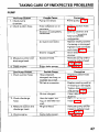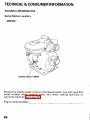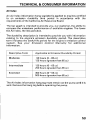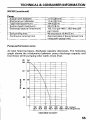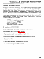
1
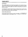
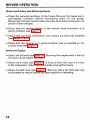
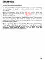
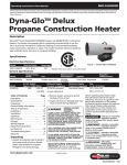
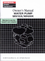
The engine exhaust from this product
contains chemicals known tothe State
of California to cause cancer, birth
defects or other reproductive harm.
Keep this owner’s manual handy,so you can refer toit a t any time.
Thisowner’smanual
is considered a permanent part of the water
pump and should remain with the water pump
resold.
if
The information and specifications included in this publication were in
effect a t thetimeofapprovalforprinting.
Honda Motor Co., Ltd.
reserves the right, however,to discontinue or change specifications or
design at any time without notice and without incurring
any obligation
whatever. No partofthispublicationmay
be reproducedwithout
written permission.
Congratulations on your selection of
a Honda water pump. Weare
certain you will be pleased with your purchase of one of the finest
water pumps on the market.
We want to help you get the best results from your new water pump
and to operate it safely. This manual contains the information on how
to dothat; please read it carefully.
As ou read this manual, you will find information preceded by a
symbol. That informationisintendedtohelpyouavoid
damage to your water pump, other property, or the environment.
We suggestyou read thewarrantypolicytofullyunderstand
its
coverage and your responsibilities of ownership. The warranty policy
is a separate document that should have been given to you by your
dealer.
When your water pump needs scheduled maintenance, keep in mind
thatyourHondaservicing
dealer is speciallytrained
in servicing
Honda water pumps. YourHonda servicingdealer is dedicated to your
satisfactionandwill
be pleased to answeryourquestionsand
concerns.
Best Wishes,
Honda Motor Co., Ltd.
1
INTRODUCTION
A FEW WORDS ABOUT SAFETY
Your safety and the safetyof others are very important. And using this
water pump safely is an important responsibility.
To help you make informed decisions about safety, we have provided
operatingproceduresandotherinformationon
labelsand inthis
manual. This information alerts you to potential hazards that could
hurt you or others.
Of course, it is not practical or possible to warn you about
all the
hazards associated with operating or maintaining a water pump. You
must use your own good judgment.
You willfindimportant
including:
0
safety informationin
a varietyofforms,
Safety Labels - on the pump.
8.and one
Safety Messages - preceded by a safety alert symbol
of three signal words,DANGER, WARNING, or CAUTION.
These signal words mean:
You WILL beKILLED or SERIOUSLYHURT if
you don‘t follow instructions.
You CANbeKILLED
or SERIOUSLYHURT
you don’t follow instructions.
if
You CAN be HURT ifyoudon’tfollow
instructions.
Safety Headings - such as IMPORTANTSAFETYINFORMATION.
Safety Section - such as PUMP SAFETY
0
Instructions - how touse this pump correctly and
safely.
This entire book is filled with important safety information - please
read it carefully.
2
PUMP SAFETY ...........................................................................................
IMPORTANT SAFETY INFORMATION .................................................
SAFETY LABEL LOCATIONS.................................................................
5
5
7
CONTROLS
COMPONENT & CONTROL LOCATIONS.............................................
8
CONTROLS ............................................................................................. 9
Fuel Valve Lever ................................................................................. 9
Ignition Switch.................................................................................... 9
Choke Lever ...................................................................................... 10
Throttle Lever ................................................................................... 10
Recoil Starter Grip ............................................................................
11
BEFORE OPERATION ..............................................................................
ARE YOU READY TO GET STARTED?................................................
IS YOUR PUMP READY TOGO? .........................................................
Check the General Condition of the Pump.....................................
Check the Suction andDischarge Hoses ........................................
Check the Engine ..............................................................................
12
12
13
13
14
14
OPERATION .............................................................................................
SAFE OPERATING PRECAUTIONS ....................................................
PUMP PLACEMENT .............................................................................
SUCTION HOSE INSTALLATION ........................................................
DISCHARGE HOSE INSTALLATION ...................................................
PRIMING THE PUMP ............................................................................
STARTING THE ENGINE .....................................................................
SETTING ENGINESPEED ....................................................................
STOPPING THE ENGINE .....................................................................
15
15
16
17
18
18
19
21
22
SERVICING YOUR PUMP ........................................................................
THE IMPORTANCE OF MAINTENANCE .............................................
MAINTENANCE SAFETY .....................................................................
MAINTENANCE SCHEDULE ...............................................................
REFUELING ...........................................................................................
FUEL RECOMMENDATIONS ..............................................................
ENGINE OIL LEVEL CHECK .................................................................
ENGINE OIL CHANGE ..........................................................................
ENGINE OIL RECOMMENDATIONS ...................................................
24
24
25
26
27
28
29
30
31
3
CONTENTS
SERVICING YOUR PUMP (continued)
AIR FILTER INSPECTION .....................................................................
AIR FILTER CLEANING ........................................................................
SEDIMENT CUP CLEANING ................................................................
SPARK PLUG SERVICE ........................................................................
IDLE SPEED ADJUSTMENT ................................................................
SPARK ARRESTER SERVICE (optional equipment) ..........................
STORAGE .................................................................................................
STORAGE PREPARATION ...................................................................
Cleaning ............................................................................................
Fuel ....................................................................................................
Engine Oil ..........................................................................................
STORAGE PRECAUTIONS ..................................................................
REMOVAL FROM STORAGE ...............................................................
TRANSPORTING
......................................................................................
TAKING CARE OF UNEXPECTED PROBLEMS......................................
ENGINE .................................................................................................
Engine Will Not Start .......................................................................
Engine Lacks Power .........................................................................
PUMP ....................................................................................................
No Pump Output ..............................................................................
Low Pump Output ............................................................................
32
33
34
35
37
38
39
39
39
40
43
43
44
45
46
46
46
46
47
47
47
TECHNICAL & CONSUMER INFORMATION .........................................
48
TECHNICAL INFORMATION ................................................................
48
48
Serial Number Location ...................................................................
...................49
Carburetor Modification for High Altitude Operation
50
Oxygenated Fuels ............................................................................
Emission Control System Information ........................................... 51
Air Index ............................................................................................ 53
54
Specifications ...................................................................................
CONSUMER INFORMATION ...............................................................
58
58
Honda Publications ..........................................................................
Customer Service Information ........................................................ 59
QUICK REFERENCE INFORMATION
............................
Inside back cover
PUMP SAFETY
IMPORTANT SAFETY INFORMATION
Honda WH15X and WH20X pumps are designed to pump only water
that is not intended for human consumption, and other
uses can result
in injury to the
operator or damage to the pump and other property.
Most accidents can be prevented if you follow all instructions in this
manual and on the pump. The most common hazards are discussed
below, along with thebest way toprotect yourselfand others.
Operator Responsibility
It is the operator’s responsibility to provide the necessary safeguards
to protect people and property. Knowhow tostop the pump quickly in
case of emergency. If you
leave the pump forany reason, always turn
the engineoff. Understand the use of all controls
and connections.
Be sure thatanyonewho
operates thepump
receives
proper
instruction. Do not let children operate the pump. Keep children and
pets awayfrom thearea of operation.
Pump Operation
Pumponlywaterthatisnotintendedforhumanconsumption.
Pumping flammable liquids,such as gasoline or fueloils, can result in
a fireor
explosion,causingserious
injury.Pumping
sea water,
beverages, acids, chemical
solutions,
or any
other
liquid
that
promotes corrosioncan damagethe pump.
Refuel With Care
Gasoline is extremely flammable, and gasoline vapor can explode.
Refuel outdoors, in a well-ventilatedarea, with theengine stopped and
the pump on a level surface. Do not fill the fuel tank above the fuel
strainer shoulder. Never smoke near gasoline, and keep other flames
and sparks away. Always storegasoline in anapprovedcontainer.
Make sure that any spilled fuel has been wiped up before starting the
engine.
5
PUMP SAFETY
Hot Exhaust
The muffler becomes very hot during operation and remains hot for
a
while after stopping the engine. Be careful not to touch the muffler
while it is hot. Let the engine cool before transporting the pump or
storing it indoors.
To prevent fire hazards, keep the pump a t least 3 feet ( 1 meter) away
from building walls and other equipment during operation.
Do not
place flammable objectsclose to theengine.
Carbon Monoxide Hazard
Exhaust gas contains poisonous carbon monoxide. Avoid inhalation of
exhaust gas. Never run the engine in
a closed garage orconfined area.
PUMP SAFETY
SAFETY LABEL LOCATIONS
The labels shown here contain important safety information. Please
read them carefully. These labels are considered permanent parts of
your pump. If a label comes off or becomes hard to read, contact an
authorized Honda servicing dealerfor a replacement.
r WARNINGDO NOT
PUMP
FLAMMABLE
OR CORROSIVEMATERIALS.
ANEXPLOSION OR FIRE
COULD RESULT, CAUSING
\SEVERE PERSONAL INJURY.
,
PUMP CAUTION LABEL
7
CONTROLS
COMPONENT & CONTROL LOCATIONS
< WHZOX>
CARRYING HANDLE
FUEL
FILLER
CAP
MUFFLER
THROTTLE LEVER
CHOKE LEVER
FUEL VALVE LEVER
STARTER GRIP
OIL DRAIN PLUG
PRIMING WATER FILLER CAP
--
8
PUMP DRAIN PLUG
CONTROLS
CONTROLS
Fuel Valve Lever
The fuel valve opens and closes
theconnectionbetweenthefuel
tank and thecarburetor.
FUEL
VALVE
LEVER
, ,
I,
The fuel valvelever must be in the
ON position for the engine run.
to
Whentheengineisnot
in use,
leave the fuel valve lever in the
O F Fp o s i t i o nt op r e v e n t
carburetor flooding and toreduce
the possibility of fuel
leakage.
Ignition Switch
IGNITION SWITCH
The ignitionswitchcontrolsthe
ignition system.
The ignition switch mustbe in the
ON position for the engine to run.
Turning the ignition switch to the
OFF position stops theengine.
9
CONTROLS
Choke Lever
The choke lever opens and closes
the choke valvein the carburetor.
CHOKE LEVER
I
The CLOSED position enriches
the fuel mixture for startinga cold
engine.
--
The OPEN positionprovidesthe
cL
correct fuel .mixture for operation
after starting, and for restarting a
warm engine.
Throttle Lever
The throttle lever controls engine
speed.
Movingthethrottle
lever inthe
directions
shown
makes
the
engine runfaster or slower.
Pump
output
is controlled
by
adjusting
the
throttle
lever.
At
maximumthrottleposition,the
pumpwilldeliverthehighest
o u t p uvt o l u m eM
. o v i n gt h e
throttle
lever
toward
the
idle
position will decrease the output
volume of the pump.
10
THROTTLE LEVER
CONTROLS
Recoil Starter Grip
Pulling the starter grip
operates the recoil starterto crank the engine.
STARTER GRIP
11
BEFORE OPERATION
ARE YOU READY TO GET STARTED?
Your safety is your responsibility. A little time spent in preparation will
significantly reduce your risk of injury.
Knowledge
Read and understand this manual. Know what the controls do and
how to operate them.
Familiarize yourself with the pump andits operation before you begin
pumping. Know what to do case
in of emergencies.
Be sure of what you are pumping. This pump is designed to pump
only water thatis not intended for human consumption.
12
BEFORE OPERATION
IS YOUR PUMP READY TO GO?
For your safety, and to maximize theservice life of your equipment,it
is very important to
take a few moments before youoperate the pump
to check its condition.Be sure to take care of any problem youfind, or
have your servicingdealer correct it, before youoperate the pump.
Improperly maintaining this pump,
or failing to
correct aproblem
before operation, couldcause a
malfunction in which you could
be
seriously injured.
Always performa preoperation
inspection before each operation,
and correct any problem.
Exhaust gas contains poisonous carbon monoxide. Avoid inhalation of
exhaust gas. Never run the engine a
in closed garageor confinedarea.
To prevent fire hazards, keep the pump a t least 3 feet (1 meter) away
from building walls and other equipment during operation.
Do not
place flammable objects closeto the engine.
Before beginning your preoperation checks, be sure the pump is ona
level surface and the ignition switch is in the
OFF position.
Check the General Conditionof the Pump
0
0
0
Look around and underneath the pump for signs of oil or gasoline
leaks.
Remove any excessive dirt or debris, especially around the engine
muffler, and recoil starter.
Look for signs of damage.
Check that all nuts, bolts, screws, hose connectors and clamps are
tightened.
13
Check the Suction andDischarge Hoses
Check the general condition of the hoses. Be sure the hoses are in
serviceable
condition
before
connecting
them
to
the
pump.
Remember that the suctionhose must be reinforced construction to
prevent hose collapse.
Check that the sealing washer in the suction hose connector is in
good condition(see page 17 ).
Check that the hose connectors and clamps are securely installed
(see pages 17 & 18 ).
Check that the strainer is in good condition and is installed on the
suction hose (see page 17 ).
Check the Engine
Check the oil level (see page 29 ). Running the engine with a low oil
level cancause engine damage.
Check the air filter(see page32 1. A dirty air filterwill restrict air flow
to thecarburetor, reducing engine and pump performance.
Check the fuel level (see page27 ). Starting with a full tank will help
to eliminate or reduce operating interruptions for refueling.
14
SAFE OPERATING PRECAUTIONS
To safely realize the full potential of this pump, you need a complete
understanding of its operation and a certain amount of practice with
its controls.
Before operating thepumpforthefirst
time, please reviewthe
IMPORTANT SAFEN INFORMATION on page 5 and the chapter titled
BEFORE OPERA TION.
For your safety, avoid starting or operating the engine in an enclosed
area, such as a garage. Your engine’s exhaust contains poisonous
carbon monoxide gas which can collect rapidly in an enclosed area
and cause illness ordeath.
Pumponlywaterthatisnotintendedforhumanconsumption.
Pumping flammable liquids,such as gasoline or fueloils, can result in
a fireor
explosion,causingserious
injury.Pumping
sea water,
beverages, acids, chemical
solutions,
or any
other
liquid
that
promotes corrosion can damage the pump.
15
OPERATION
PUMP PLACEMENT
For best pump performance, place the pumpnear the water level, and
usehoses that are no longer than necessary. That will enable the
pump toproduce the greatest output
with theleast self-priming time.
As head (pumpingheight)
increases, pumpoutput
decreases.
Maximumhead specificationsand
pump performancecurves are
shown in the tables on pages 55 and 57. The length, type, and size of
the suction and dischargehoses can also significantly affect pump
output.
Discharge
head
capability
is
always
greater than
suction
head
capability, so it is important forsuction head to be the shorter part of
total head.
Minimizing suction head (placing the pump near the water level) is
also very important for reducing self-priming time. Self-priming time
is the timeit takes the pumpto bring water thedistance of the suction
head during initial operation.
16
OPERATION
,
SUCTION HOSE INSTALLATION
Use thecommerciallyavailablehoseandhoseconnector
with the
hose clampprovided with thepump. Thesuctionhosemustbe
reinforced with a noncollapsiblewall or braided wire construction.
The
suction
hose
should
be
no
longer
than
necessary. Pump
performance is best when the pump is near the water
level, and the
hoses are short.
Use a hose clamp tosecurely fasten the hose connectorto the suction
hose in order to prevent
air leakage and loss of suction. Verify that the
hose connector sealing washer in
is good condition.
Install the strainer (provided with the pump) on the other end of the
suction hose, and secure it with a hose clamp. The strainerwill help to
prevent the pump from becoming clogged or damaged
debris.
by
Securely tighten thehose connector on the pump suction port.
SUCTION PORT
SEALING WASHER
HOSE CLAMP RING
(commercially available)
SUCTION HOSE
(commercially
available)
i
!
CONNECTOR
HOSE CLAMP
17
OPERATION
DISCHARGE HOSEINSTALLATION
Use a commercially
available
hoseandhoseconnector,and
clamp provided with the pump.
HOSE CONNECTOR
(com/mercially available)
DISCHARGE HOSE
It is best t o use a short, large-diameter hose, because that will
reduce fluid friction and improve
pumpoutput. A longor smalldiameter hose will increase fluid
friction andreduce pump output.
Tighten the hose clamp securely
topreventthedischarge
hose
from disconnecting
under
high
pressure.
HOSE CLAMP
PRIMING THE PUMP
Beforestartingthe
engine,remove thefillercapfromthepump
chamber, and completely fill the pump chamber withwater. Reinstall
the fillercap, and tightenit securely.
I NOTICE I
Operating the pump dry willdestroy the pump seal. If the pump has
been operated dry, stop the engine immediately, and
allow the pump
to cool before priming.
PRIMING WATER FILLER CAP
18
OPERATION
STARTING THE ENGINE
1. Prime the pump(see page 18 ).
2. Move the fuel valve
lever to theON position.
FU-ELVALVE LEVER
3. To start acold engine, move thechoke lever to theCLOSED position.
To restart a warm engine, leave the choke lever in the OPEN position.
CHOKE LEVER
4. Move the throttle lever away from the SLOW position, about 1/3 of
the way toward the
FAST position.
THROTLE LEVER
19
OPERATION
5. Turn the ignition switch to the
ON position.
,
IGNITION SWITCH
6. Pull thestarter grip lightly untilresistance is felt, then pullit briskly.
Do not allow thestarter grip tosnap back against the engine. Return
it gently to prevent damage the
to starter.
STARTER GRIP
20
OPERATION
7. If the choke lever was moved to the CLOSED position to start the
engine, gradually moveit to theOPEN position as the engine warms
UP.
SETTING ENGINE SPEED
After starting the engine, move the throttle lever to the FAST position
for self-priming, andcheck pump output.
Pumpoutputiscontrolledbyadjustingengine
speed. Moving the
throttle lever in the FAST direction will increase pump output,and
moving the throttle lever in the SLOW direction will decrease pump
output.
THROlTLE LEVER
21
OPERATION
STOPPING THE ENGINE
To stop the enginein an emergency, simply turn the ignition switch to
Under
normal
conditions,
use the
following
the OFF position.
procedure.
1. Move the throttle lever to SLOW
the
position.
THROlTLE LEVER
2.Turn the ignition switch to the
OFF position.
u!
I
IGNITION SWITCH
22
_-I
I ,
OPERATION
3. Turn the fuelvalve leverto theOFF position.
/
FUEL. VALVE LEVER
OFF
After use, remove the pump drain plug (see page40 ), and drain the
pump chamber. Remove the filler cap, and flush the pump chamber
with clean, freshwater.Allow
the watertodrainfromthepump
chamber, then reinstall the fillercap and drain plug.
23
SERVICING YOUR PUMP
THE IMPORTANCE OF MAINTENANCE
Good maintenance is essential for safe, economical, and trouble-free
operation. Itwill also help reduce airpollution.
'
Improperly maintaining this pump,
or failure to correct
a problem
before operation,can cause a
malfunction in which you
can be
seriously hurt or killed.
Always follow the inspection and
maintenance recommendations and
schedules in this owner's manual.
To help you properly care for your pump, the followingpages include
a maintenance schedule, routine inspection procedures, and simple
maintenance procedures using basic hand tools. Other service tasks
that are more difficult, or require
special tools, are best handled by
professionals and are normally performed by a Honda technician or
other qualified mechanic.
The maintenance schedule applies to normal operating conditions. If
you operate your pump under severe conditions, such as sustained
high-load or high-temperature operation, or use in unusually wet or
dusty conditions, consult your servicing dealer for recommendations
applicable to your individual
needs anduse.
Remember that your servicing dealer knows your pump best and is
fully equipped to maintain and
repair it.
To ensurethebestqualityandreliability,
use only new, genuine
Honda parts ortheir equivalents for repair and replacement.
Maintenance, replacement, or repair of emission control devices and
systems may be performed by any engine repair establishment or
individual, using parts that are
"certified" t o EPA standards.
SERVICING YOUR PUMP
MAINTENANCE SAFETY
Some of the most important safety precautions follow. However, w e
cannotwarnyouofevery
conceivable hazard that can arise in
performing maintenance.Only you candecidewhether
or not you
should performa giventask.
Failure to properly follow
maintenance instructions and
precautions can cause you to be
seriously hurt orkilled.
Always followthe procedures and
precautions in the owner's manual.
Safety Precautions
Make sure the engine is off before you begin any maintenance or
repairs. This will eliminate several potential hazards:
-Carbon monoxide poisoning from engineexhaust.
Be sure there is adequate ventilation whenever you operate the
engine.
-Burns from hotparts.
Let the engine and exhaust system cool before touching.
-Injury from moving parts.
Do not run the engine
unless instructedto doso.
0
0
Read the instructions before you begin, and make sure
you have the
tools andskills required.
To reduce thepossibilityoffireor
explosion,becareful
when
workingaround gasoline. Use only a nonflammable solvent, not
gasoline, to clean parts. Keep cigarettes, sparks, and flames away
from allfuel-related parts.
25
SERVICING YOUR PUMP
MAINTENANCE SCHEDULE
Emission-related items.
(1) Service more frequently whenused in dusty areas.
(2) These itemsshouldbeserviced
by your servicing dealer, unless you
have the proper tools and are mechanically proficient. Refer t o Honda
shop manual forservice procedures.
(3) For commercial use, log hoursofoperationtodetermineproper
maintenance intervals.
26
SERVICING YOUR PUMP
REFUELING
Fuel tank capacities
WH15X: 0.66 US gal (2.5 !2,0.55 Imp gal)
WH20X: 0.95 US gal (3.6 2! ,0.79 Imp gal)
With the engine stopped, remove the fuel tankcap and check the fuel
level. Refillthe tank if the fuel
level is low.
Gasoline is highly flammable and
explosive.
You can be burned orseriously
injured when handling
fuel.
Stop the engine and
keep heat,
sparks, and flameaway.
Handle fuel only outdoors.
Wipe up spills immediately.
27
SERVICING YOUR PUMP
Refuel in a well-ventilated area before starting theengine. If the engine
has been running,allow it to cool. Refuel carefully to avoid spilling fuel.
Do not fill the fuel tank
above the fuelstrainer shoulder. After refueling,
tighten the fuel tank cap
securely.
Never refuel the engine inside a building where gasoline fumes may
reach flames or sparks. Keep gasoline away fromappliance pilot lights,
barbecues, electric appliances, power tools, etc.
Spilled fuel is not onlya fire hazard, it causes environmental damage.
Wipe up spills immediately.
Fuel can damage paint and plastic. Be careful not to spill fuel when
filling your fuel tank. Damage caused b y spilled fuel is not covered
under warranty.
FUEL RECOMMENDATIONS
Use unleaded gasoline with a pumpoctane rating of 86 or higher.
These engines are certifiedto operate on unleaded gasoline. Unleaded
gasoline produces fewer engine and spark plug deposits and extends
exhaust system life.
Never use stale or contaminated gasoline or an oil/gasoline mixture.
Avoid gettingdirt or water in the fuel
tank.
Occasionally youmay
heara
light "spark knock" or"pinging"
(metallic rapping noise) while operating under heavyloads. This is no
cause for concern.
Ifsparkknock
or pinging occurs at a steadyengine
normal load, change brands of gasoline. If spark knock
persists, see an authorized Honda servicing
dealer.
speed, under
or pinging
Running the engine with persistent spark knock or pinging can cause
engine damage.
Running the engine with persistent spark knock or pinging is misuse,
and the Distributor's Limited Warrantydoes not cover parts damaged
by misuse.
28
SERVICING YOUR PUMP
ENGINE OIL LEVEL CHECK
Check theengineoil
position.
level with the engine stopped and in
alevel
1. Remove the oil fillercap/dipstick andwipe it clean.
2. Insert and remove the dipstick without screwing
it into the fillerneck.
Check the oillevel shown onthe dipstick.
3. If the oil level is low, fill to the edge of the oil filler hole with the
recommended oil(see page 31 ).
4. Screw in the oil fillercap/dipstick securely.
OIL FILLER NECK
\
UPPER LIMIT
OIL FILLER CAP/DIPSTICK
pfiZ7
Running the engine
with a low oillevel can causeengine damage.
29
SERVICING YOUR PUMP
ENGINE OIL CHANGE
Drain the used oil while the engine is warm. Warm oil drains quickly
and completely.
1. Place a suitable container below the engine
to catch the used oil,
then remove the oil filler
cap/dipstick and the drain plug.
2.Allow the used oil to drain completely, then reinstall the drainplug,
and tightenit securely.
Please dispose of used motor oil in
a manner that is compatible with
the environment. Wesuggest you take used oil in a sealed container
to your local recycling center or service station for reclamation. Do
not throwit in the trash,pour it on the ground,or downa drain.
3. With the engine in a level position, fill to the outer edge of the oil
filler hole with the recommended (see
oil page 31 ).
Engine oil capacity: 0.63 US qt (0.60 0, 0.53 Imp qt)
Running the enginewith a low oillevel can causeengine damage.
4. Screw in the oil filler cap/dipstick
securely.
OIL LEVEL
I
DRAIN PLUG
OIL FILLER CAP/DIPSTICK
30
SERVICING YOUR PUMP
ENGINE OIL RECOMMENDATIONS
Oil is a major factor affecting performance and service life. Use
4-stroke automotive detergent oil.
SAE IOW-30 is recommendedfor general use. Other viscosities shown
in the chart may
be usedwhen theaverage temperature in yourarea is
wit.hin the recommendedrange.
SAE Viscosity Grades
-30
-20 -1 0 0
10 20
30 4OoC
AMBIENT TEMPERATURE
The SAE oil viscosity and service classification are in the API label on
the oil container.Hondarecommends
thatyou use API SERVICE
category SJ oil.
The recommended operating range of this
pump is23 O F to 104 O F (-5
OC to 40 "C).
31
I
SERVICINGYOUR PUMP
AIR FILTER INSPECTION
Unscrew the wing nut and remove theair cleaner cover. Check the air
filter tobe sureit is clean and in good condition.
If the air filter is dirty,
clean it as described on page 33. Replace the air
filter ifit is damaged.
Reinstall the air filter and air
cleaner cover. Be sure all the parts shown
below are in place. Tighten the wing nut
securely.
W
I
Operating the enginewithout an air filter, or with adamaged air filter,
will allow dirt enter
to
theengine, causing rapid enginewear. This type
of damage isnot covered by the Distributor's Limited Warranty.
AIR CLEANER COVER
COVER WASHER
AIR FILTER
GRID
32
SERVICING YOUR PUMP
AIR FILTER CLEANING
A dirty air filterwill restrict air flow to the
carburetor, reducing engine
performance. If you operate the pump in very dusty areas, clean the
airfiltermorefrequentlythan
specified in the MAINTENANCE
SCHEDULE (see page 26 ).
1. Clean the air filter in warm soapy water, rinse, and allow to dry
thoroughly. Or clean in nonflammable solvent and allow to dry.
2. Dip the air filter in clean engine oil, then squeeze out all excess oil.
The engine will smoke when started if too much oil is left in the
foam.
3. Wipe dirt from the air
cleaner base and cover, using a moist rag. Be
careful to prevent dirt from entering the carburetor.
33
'
SERVICINGYOUR PUMP
~
SEDIMENT CUP CLEANING
1. Move the fuel valvelever to the OFF position, then remove the fuel
sediment cup and O-ring.
Gasoline is highly flammable and
explosive.
You can be burned orseriously
injured when handling fuel.
Stop the engine and
keep heat,
sparks, and flameaway.
Handle fuel only outdoors.
Wipe up spills immediately.
2. Wash the sediment cup and O-ring in nonflammable
dry them thoroughly.
solvent, and
3. Place the O-ring in the fuel
valve, and install the sediment
Tighten the sediment cup
securely.
cup.
4. Move the fuel valve lever to the ON position, and check for leaks.
Replace the O-ring if there is any
leakage.
O-RING
34
SERVICING YOUR PUMP
SPARK PLUG SERVICE
In order to service the spark plug, you will need a spark plug wrench
(commercially available).
Recommended spark plug:BPR6ES (NGK)
W20EPR-U(DENSO)
Incorrect spark plugs can causeengine damage.
1. Disconnect the spark plug cap, and remove any dirt from around the
spark plug area.
2. Remove the spark plug witha 13/16-inch spark plug wrench.
SPARK PLUG WRENCH
3. Inspect the spark plug. Replace it
if theelectrodes are worn, or if the
insulatoris cracked or chipped.
Clean the spark plug with a wire
brush if youare going toreuse it.
0.028-0.031 in
(0.70-0.80 rnrn)
i
I
~
4. Measure the spark plug electrode
gap witha suitable gauge.
Correct the gap, if necessary, by
c a r e f u l l yb e n d i n gt h es i d e
electrode.
The gap shouldbe:
0.028-0.031 in (0.70-0.80 mm)
5. Install the spark plug carefully, by hand, t o avoid cross-threading.
35
~
SERVICING YOUR PUMP
6.Afterthe spark plug seats, tightenwith
wrench to compress the washer.
If reinstalling the used
spark plug seats.
a 13/16-inch spark plug
sparkplug, tighten 118-1/4 turn after the
If installing a new spark plug, tighten 1/2 turn after the spark plug
seats.
A loose spark plug can overheat anddamage the engine.
Overtighteningthe
spark plug can damage thethreads
cylinder head.
7. Attach thespark plug cap.
36
in the
SERVICING YOUR PUMP
IDLE SPEEDADJUSTMENT
1. Start the engine outdoors, and allow
temperature.
it to warm up to
operating
pEiGl
Dry operation will damage the pump seal.Be
sure thepump
chamber is filled with
water before starting the
engine.
2. Move the throttle
lever to its slowest position.
3. Turn the throttle stop screw to obtain the standard
speed.
idle
Standard idlespeed: 1,400 ?% rpm
THROlTLE STOP SCREW
37
SERVICING YOUR PUMP
SPARK ARRESTER SERVICE(optional equipment)
Your engine is not factory-equipped with a spark arrester. In some
areas, it is illegal to operate an engine withouta spark arrester. Check
local
laws
and
regulations.
A spark arrester is
available
from
authorized Honda servicingdealers.
Thesparkarrester
mustbe
functioning as designed.
servicedevery
100 hoursto
keep it
If the enginehas been running, the mufflerwill be very hot. Allow the
muffler to cool before servicing the
spark arrester.
1. Remove thetwo 8 mm nuts, and remove the muffler.
2. Remove the four5 mm self-tapping screws, and remove the muffler
protector from the muffler.
3.Remove the 4 m m screw from the spark arrester, and remove the
spark arresterfrom the muffler.
5 rnrn SELF-TAPPING
MUFFLER PROTECTOR
4 rnrn SCREW
SPARK ARRESTER
4. Use a brush t o remove carbon
deposits from thespark arrester
screen. Be careful
to
avoid
damaging thescreen.
The spark arrester must be free
of breaks and holes. Replace
thesparkarresterif
it is
damaged.
SPARK ARRESTER SCREEN
5. Installthe spark arrester, muffler protector, andmufflerinthe
reverse order ofdisassembly.
38
STORAGE PREPARATION
Proper
storage
preparation
is essential for keeping yourpump
troublefree and looking good. The following steps will help to keep
rust
and
corrosion
from
impairing
your
pump's
function
and
appearance, and will make the engineeasier to start when you
use the
pump again.
Cleaning
1. Wash the engineand pump.
Wash the engine by
hand, and be careful to prevent water from
entering the air cleaner or muffler opening. Keep water away from
controlsandallother
places that are difficultto dry, as water
promotes rust.
I NOTICE 1
0
0
Using a garden hose or pressure washing equipment can force
water into the air cleaner or muffler opening. Water in the air
cleaner will soak the air filter, and water that passes through the
air filter or muffler
can enter the cylinder, causing damage.
Water contacting a hot engine can cause damage. If the engine
has been running, allow it to cool for atleast half an hour before
washing.
2. Wipe dry allaccessible surfaces.
3. Fill the pump chamber with clean, fresh water, start the engine
outdoors, and let it run
until
it reaches normal
operating
temperature to evaporate any external water.
1Dry operation will damage the pump seal. Be sure the pump
chamber is filled withwater before starting theengine.
39
STORAGE
4. Stop the engine, and allow it to
cool.
5. Remove the pump drain plug,
and flush the pump with clean,
fresh water. Allow the water to
drain from the pump chamber,
then reinstall the drain plug.
6. After the pump is clean and
dry,
touchup any damaged paint,
andcoat areas thatmayrust
with a light film of oil. Lubricate
controls with a siliconespray
lubricant.
PUMP DRAIN PLUG
Fuel
Gasoline will oxidizeanddeteriorateinstorage.Oldgasoline
will
cause hardstarting,and
it leaves gumdepositsthatclogthefuel
system. If the gasoline in your engine deteriorates during storage, you
may need to have the carburetor and other fuel system components
serviced or replaced.
The length of time that gasoline
can be left in your fuel
tankand
carburetor without causing functional problems will vary with
such
factors as gasoline blend, your storage temperatures, and whether the
fuel tank is partially or completely filled.The air in a partially filled fuel
tank promotesfueldeterioration.
Very warmstorage/temperatures
accelerate fuel deterioration. Fuel deterioration problems may occur
within a few months, or evenless if the gasoline was not fresh when
you filled the fuel tank.
The Distributor'sLimitedWarranty
does notcoverfuelsystem
damageorengineperformanceproblemsresultingfromneglected
storage preparation.
Youcan extend fuel storage life
by adding a fuel stabilizer that is
formulatedforthatpurpose,oryou
can avoidfueldeterioration
problems by draining the fuel
tank and carburetor.
I
STORAGE
Adding a Fuel Stabilizer
to Extend Fuel Storage
Life
When adding a fuel stabilizer, fill the fuel tank with fresh gasoline. If
onlypartially filled, airinthe
tank will promotefueldeterioration
during storage. If you keep a container of gasoline for refueling, be
sure that it contains only freshgasoline.
1. Add fuelstabilizer following themanufacturer’s instructions.
2. After addinga fuel stabilizer, run the engine outdoors for
10 minutes
to be sure that treated gasoline
has replaced the untreated gasoline
in thecarburetor.
pmq
Dryoperation
will damage the pump seal. Be surethe
chamber is filled withwater before starting the
engine.
pump
3. Stop theengine, and move the fuel valve
lever to theOFF position.
/
OFF
FUEL VALVE LEVER
41
STORAGE
Draining the Fuel Tank and Carburetor
1. Place an approved gasoline container below the
carburetor, and use
a funnel to avoid spilling fuel.
2. Remove the carburetor drain bolt and sedimentcup, then move the
fuel valve lever to the
ON position.
Gasoline is highly flammable and
explosive.
You can be burned or seriously
injured when handling fuel.
Keep heat, sparks, and flame
away.
Handle fuel only outdoors.
Wipe up spills immediately.
DRAIN BOLT
SEDIMENT' CUP
3.After all the fuel has drained into the container, reinstall the drain
bolt and sedimentcup. Tighten themsecurely.
42
STORAGE
Engine Oil
1. Change the engine oil(see page30 ).
2. Remove the spark plug (see page 35 ).
3. Pour a tablespoon(5- 10 cc) ofclean engine oil into the cylinder.
4. Pull the starter grip several times to distribute the oil
in thecylinder.
5. Reinstall the spark plug.
6.Pull the starter grip slowly until resistance is felt and the notch on
the starter pulley aligns with the hole at the top of the recoil
starter
cover. Thiswill close the valves so moisture cannot enter the engine
cylinder. Return the
starter grip gently.
Align notch onpulley with
hole at topof cover.
STORAGE PRECAUTIONS
Ifyourpumpwill
bestoredwithgasolineinthefueltank
and
carburetor, it is important to reduce the hazard ofgasolinevapor
ignition. Select a well-ventilated storagearea away from anyappliance
that operates with a flame, such as a furnace, water heater, or clothes
dryer. Also avoid any area with a spark-producing electric motor, or
where power toolsare operated.
If possible, avoidstorage areas with highhumidity,
promotes rust and corrosion.
because that
Unless all fuelhas been drainedfrom the fuel
tank, leave the fuel valve
lever in theOFF position toreduce the possibility of fuel
leakage.
43
STORAGE
Place the pump ona level surface. Tilting can cause fuel or oilleakage.
With the engine and exhaust system
cool, cover the pump tokeep out
dust. A hotengineandexhaustsystem
can igniteormeltsome
materials. Do not use sheet plastic as a dust cover. A nonporous cover
will trap moisture around the pump, promoting rust and corrosion.
REMOVAL FROMSTORAGE
Check your pump as described in theBEFORE OPERATIONchapter of
this manual.
If the fuel was drained during storage preparation,
fill the tank with
be
fresh gasoline. If you
keep a container of gasoline for refueling,
surethat
it containsonlyfreshgasoline.Gasoline
oxidizesand
deteriorates over time, causing hard starting.
If the cylinder was coated
with oil during storage preparation, the
engine may smoke briefly
at startup. Thisis normal.
44
TRANSPORTING
If the pump has been running, allow the engine to cool forat least 15
minutesbeforeloadingthepump
on thetransport vehicle. A hot
engineandexhaustsystem
can burnyouand
can ignitesome
materials.
Keep the pump level when transporting to
reduce the possibility of
fuel leakage. Move the fuel valve
lever to theOFF position.
45
TAKING CARE OF UNEXPECTED PROBLEMS
ENGINE
Engine Will Not Start
1. Check control
positions.
Possible Cause
Fuel valve OFF.
Correction
Move fuel valve lever
to ON position.
Move choke lever to
CLOSED position
unless engine is warm.
Turn ignition switch to
Choke open.
Ignition switchOFF.
2. Check fuel.
3. Remove and inspect
spark plug.
fuel.
of
Out
Bad fuel; pumpstored
without treating or
draining gasoline, or
refuel with bad
gasoline.
Spark plug faulty,
fouled, or improperly
gapped.
Spark plug wet with
fuel (flooded engine).
4. Take engine to an
authorized Honda
servicing dealer, or
refer to shopmanual.
Engine Lacks Power
1. Check air filter.
2. Check fuel.
3. Take engine to an
authorized Honda
servicing dealer, or
refer to shop manual.
46
Fuel filter clogged,
carburetor malfunction,
ignition malfunction,
valves stuck, etc.
Possible Cause
Air filter clogged.
Bad fuel; pump stored
without treating or
draining gasoline, or
refuel with bad
gasoline.
Fuel filter clogged,
carburetor malfunction,
ignition malfunction,
valves stuck, etc.
I
I
ON.
~ ~ _ _ _
Refuel
(p.
27
Drainfueltankand
carburetor (p. 42 ).
Refuel with fresh
gasoline (p. 27 ).
Clean, gap, or replace
spark plug (p. 35 ).
Dry and reinstallspark
plug. Start engine with
throttle lever inFAST
position.
Replace or repair faulty
components as
necessary.
Correction
Clean or replace filter
(P. 33 1.
Drain fuel tank and
carburetor (p. 42 ).
Refuel with fresh
gasoline (p. 27 ).
Replace or repair faulty
components as
necessary.
TAKING CARE OF UNEXPECTED PROBLEMS
PUMP
No Pump Output
1. Check pump
chamber.
2. Check suction hose.
Possible Cause
Pump not primed.
Hose collapsed, cut or
punctured.
Strainer not completely
underwater.
I
Air leak at connector.
I
Strainer clogged.
Correction
Prime pump(p. 18 )
Replace suction hose
(P. 17 1.
Sink the strainer and
the end ofa suction
hose completely
underwater.
Replace sealing washer
if missing ordamaged.
Tighten hose connector
and clamp(p. 17 1.
Clean debris from
strainer.
Relocate pump and/or
hoses to reduce head
(p. 16,55,57 ).
3. Measure suction and
discharge head.
Excessive head.
4. Check engine.
Engine lacks power.
See page 46.
Low Pump Output
1. Check suction hose.
Possible Cause
Hose collapsed,
damaged, too long, or
diameter too small.
Air leak at connector.
Correction
Replace suction hose
(p. 17 ).
Strainer clogged.
2. Check discharge
hose. hose
3. Measure suction and
discharge head.
4. Check engine.
Hose damaged, too
long, or diameter too
small.
Marginal head.
lacks power.
Replace sealing washer
if missing or damaged.
Tighten hose connector
and clamp (p. 17 1.
Clean debris from
strainer.
Replace discharge
(p. 18 1.
Relocate pump and/or
hoses to reduce head
(p. 16, 55, 57 ).
See page 46. Engine
47
TECHNICAL & CONSUMER INFORMATION
TECHNICAL INFORMATION
Serial Number Location
<WH20X >
ENGINE SERIAL NUMBER
Record the engineserial number in thespace below. Youwill need this
serial number when ordering parts, andwhenmakingtechnical
or
warranty inquiries(see page 59).
Engine serial number:
48
TECHNICAL & CONSUMER INFORMATION
Carburetor Modification for High Altitude Operation
At high altitude, the standard carburetor air-fuel mixture will be too
rich. Performance will decrease, and fuel consumption willincrease. A
very rich mixture will also foul the spark plug and cause hard starting.
Operation at an altitude that differs
from that at which this engine was
certified, for extended periods of time, may
increase emissions.
High altitude performance can be improved by specific modifications
to the carburetor. If you always operate your pump at altitudes above
5,000 feet (1,500 meters), have your servicing dealer perform this carburetor modification. Thisengine, when operated a t high altitude with
thecarburetormodificationsforhighaltitude
use, will meet each
emission standard throughout its useful life.
Even with carburetor modification, engine horsepower will decrease
about 3.5% for each1,000-foot (300-meter) increase in altitude. The
effect ofaltitudeonhorsepower
will begreater
thanthisifno
carburetor modification ismade.
W
I
When the carburetor has been modified for high altitude operation,
the air-fuel mixture will be toolean for low altitudeuse. Operation at
altitudes below 5,000 feet (1,500 meters) with a modified carburetor
may cause the engineto overheat and result in
serious engine damage.
Foruse
atlow altitudes, have yourservicing
dealer returnthe
carburetor to originalfactory specifications.
49
I
TECHNICAL & CONSUMERINFORMATION
Oxygenated Fuels
Some conventional gasolines are being blended with alcohol or
an
ether compound. Thesegasolines
are collectivelyreferredto
as
standards, some areas ofthe
oxygenated fuels. To meetcleanair
United States and Canadause
oxygenatedfuelstohelpreduce
emissions.
If you use an oxygenated fuel, be sure it is unleaded and meets the
minimum octane rating requirement.
Before using an oxygenated fuel, try to confirm the fuel‘s contents.
Some states/provinces require this information to
be posted on the
pump.
The following are the EPA-approved percentages of oxygenates:
ETHANOL
MTBE
~
(ethyl or grain alcohol)
10% by volume
You may use gasoline containing up to 10% ethanol
byvolume.Gasolinecontainingethanolmay
be
marketed under the name “Gasohol”.
(methyl
tertiary
butyl
ether)
15% by
volume
You may use gasoline containing up to15% MTBE by
volume.
METHANOL -(methyl or wood alcohol) 5% by volume
You may use gasoline containing up to5% methanol
by volume as long as it also contains cosolvents and
corrosioninhibitorstoprotectthefuelsystem.
Gasolinecontainingmorethan
5% methanolby
volume
may
cause starting
and/or
performance
problems.Itmay
alsodamagemetal,rubber,and
plastic parts of your fuel system.
If you notice any undesirable operating symptoms, try another
service
station, or switch to another brand gasoline.
of
Fuel system damage or performance problems resulting from the use
of an oxygenatedfuelcontainingmorethanthepercentagesof
oxygenates mentioned aboveare not covered under warranty.
50
TECHNICAL & CONSUMER INFORMATION
Emission Control System Information
Source of Emissions
The combustion process
produces
carbon
monoxide,
oxides
of
nitrogen, and hydrocarbons. Control
of hydrocarbons and oxides of
nitrogenisveryimportant
because, undercertainconditions,
they
react to formphotochemical smog whensubjected to sunlight. Carbon
monoxide does not react in thesame way, but it is toxic..
Honda utilizes lean carburetor settings and other systems
the
emissions
of
carbon
monoxide,
oxides
of
nitrogen,
hydrocarbons.
to reduce
and
The U.S. and California Clean Air Acts
EPA andCaliforniaregulationsrequire
allmanufacturers to furnish
written instructionsdescribing the operation and maintenance of emission control systems.
The following instructions and procedures must be followed in order
to keep the emissions from your Honda engine within the emission
standards.
Tampering andAltering
Tampering with or altering the emission control system may increase
emissions beyond the legal limit. Among those acts that constitute
tampering are:
0
0
Removal or alteration of any part of the
systems.
Alteringordefeatingthegovernor
mechanism to cause theengineto
parameters.
intake, fuel, or exhaust
linkage or speed-adjusting
operateoutside
itsdesign
51
'
TECHNICAL & CONSUMER INFORMATION
Problems That May Affect Emissions
If you are aware of any of the following symptoms,have your engine
inspected and repaired by your servicing
dealer.
Hard starting or stalling after starting.
Rough idle.
Misfiring or backfiring underload.
Afterburning (backfiring).
0
Black exhaust smoke or high fuel consumption.
Replacement Parts
The emission control systems on your Honda engine were designed,
built,andcertifiedtoconformwith
EPA andCaliforniaemission
regulations. We recommend
the
use of
genuine
Honda
parts
whenever
you
have
maintenance
done.
These original-design
replacement parts are manufactured to the samestandards as the
original parts, so you can be confident of their performance. The use
of replacement parts that are not of the original design and quality
may impair the effectiveness of your emission control system.
A manufacturer of an aftermarket part assumes the responsibility that
the
part
will
not
adversely
affect
emission
performance.
The
manufacturer or rebuilder of the part must certify thatuse of the part
will not result in a failure of the engine to comply with emission
regulations.
Maintenance
Follow the maintenance schedule on page 26 . Remember that this
schedule is based on the assumption that your machine will be used
foritsdesignedpurpose.Sustainedhigh-loadorhigh-temperature
operation, or use in unusually wet or dusty conditions,
will require
more frequentservice.
52
TECHNICAL & CONSUMER INFORMATION
Air Index
An Air Index Information hang tag/label is applied to engines certified
durability
time
period
in
accordance with
the
t o an emission
requirements ofthe California Air Resources Board.
The bar graph is intended to provideyou, our customer, the ability to
compare the emissions performance of available engines. The lower
the AirIndex, the less pollution.
The durability description is intended to provide you with information
relating to the engine’s emissiondurabilityperiod. Thedescriptive
term indicates the useful-life period for the engine’s emission control
system. See your EmissionControlWarranty
foradditional
information.
Descriptive Term
Applicable to Emission Durability Period
Moderate
50 hours (0-65 cc)
125 hours (greater than65 cc)
Intermediate
125 hours (0-65 cc)
250 hours (greater than65 cc)
Extended
300 hours (0-65 cc)
500 hours (greater than65 cc)
The Air Index Information hang tag must remain
on the pump untilit is
sold. Removethe hang tag before operating the pump.
53
TECHNICAL & CONSUMER INFORMATION
Specifications
WH15X
Dimensions and weight
16.3 in (415 m m )
14.2 in (360 mm)
15.9 in (405 m m )
49 Ibs (22 kg)
Length
Height
Dry weight
Width
Engine design and performance
I
Model
Engine type
Displacement
[bore X stroke]
Maximum torque
Cooling system
Ignition system
PTO shaft rotation
I GX120K1
I
I
Tuneup
Spark plug gap
Idle speed
Valve clearance
(cold)
Other specifications
54
1
4-stroke, overhead valve, single cylinder
7.3 cu-in (119 cc)
[2.4 X 1.7 in (60 X 42 m m ) ]
3.9 bhp (2.9 kW, 4.0 PS) at 4,000 rpm Maximum output
5.4 ft-lb (7.4 N.rn, 0.75 kg-rn) at 2,500 rpm
Forced air
Transistorizedmagneto
Counterclockwise
0.028 - 0.031 i n
See page 35.
(0.70-0.80 m m )
1,400
rpm
See page 37.
Intake:0.15
k 0.02 mm
See shop
0.20 k 0.02 mm
manual. Exhaust:
No other adjustments needed.
2:
TECHNICAL & CONSUMER INFORMATION
WH15X (continued)
'ump
Suction port diameter
Discharge port diameter
Total head (maximum)
Suction head (maximum)
Discharge capacity (maximum)
Self-priming time
Continuous running time
I
1
I
1.5 in (38 mm)
1.5 in (38mm)
164ft (50 m )
26.2 ft (8 m)
105.7 US gal (400 !2,88.0Imp gal)
Der minute
40 seconds at 16.4 ft (5m )
Approximately 2 hours (actual time
varies with DumD load)
Pump performancecurve
As total head increases, discharge capacity decreases. The following
graph shows the relationship between pump discharge capacity and
total head, while pumping clear water atsea level.
164
131
3I
98
a
c
66
33
(Q/min)
(US g a l h i n )
DISCHARGE CAPACITY
55
TECHNICAL & CONSUMER INFORMATION
WH20X
Dimensions and weight
17.1 i n (435 m m )
14.8 in (375 m m )
15.7 i n (400 mm)
51.8 Ibs (23.5 kg)
Length
Width
Height
Dry weight
Engine design and performance
Model
Engine type
Displacement
[bore X stroke]
Maximum output
Maximum torque
Cooling system
GX160K1
4-stroke, overhead valve, single cylinder
9.9cu-in (163 cc)
[2.7 X 1.8 in (68 X 45 m m ) ]
5.4 bhp (4.0 kW, 5.5 PS)at 4,000 rpm
8.0 ft-lb (11 N-m, 1.Ikg-m) at2,500 rpm
Forced air
Transistorized magneto Ignition system
Counterclockwise
PTO shaft rotation
Tuneup
I
Spark plug
gap
Idle speed
Valve clearance
(cold)
56
I
0.028-0.031 i n
I See page 35.
(0.70-0.80 m m )
1,400
rpm
See page 37.
Intake: 0.15 -t 0.02 m m
See shop
manual.
Exhaust: 0.20 k 0.02 mm
No other adjustmentsneeded. Other specifications
2::
TECHNICAL & CONSUMER INFORMATION
WHPOX (continued)
Pump
1
Suction port diameter
Discharge port diameter
Total head (maximum)
Suction head (maximum)
Discharge capacity (maximum)
Self-priming time
Continuous running
- time
I
2 in (50 mm)
2 in (50 m m )
164ft (50 m)
26.2 ft (8m)
132.1 US gal (500 0, 110.0 Imp gal)
per minute
60 seconds at 16.4 ft (5m)
Approximately 2-1/10 hours (actual
time varies with pump load)
Pump performance curve
As total head increases, discharge capacity decreases. The
following
graph shows the relationship between pump discharge capacity and
total head, whilepumping clear water at sea level.
(ft)
(m)
164
131
3
I
98
-I
2
?
66
33
0
loo 200
26.4
52.8
79.3
I
I
300
I
700
600
500
400
(Q/min)
105.7 132.1 158.5 184.9 (US gallmin)
I
I
I
I
DISCHARGE CAPACITY
57
TECHNICAL & CONSUMER INFORMATION
~~
CONSUMER INFORMATION
Honda Publications
These
publications
will
give
you
additional
information
for
maintaining and repairing your pump.You may order them from your
Honda pump dealer.
Shop Manual
This manual covers complete maintenance and overhaul
procedures.
It is intended tobe used bya skilled technician.
Parts Catalog
This manual provides complete, illustrated parts lists.
58
TECHNICAL & CONSUMER INFORMATION
Customer Service Information
Servicing dealership personnelare trained professionals. They should
be able to answer any question you may have. If you encounter a
problem that your dealer does not solve to your satisfaction, please
discuss it with the dealership's management. The Service Manager or
General Manager can help. Almost all problems are solved in this way.
If you are dissatisfied with the decision madebythe
management,
contact
the
Honda
Power
Equipment
Customer
Relations Office. You can write:
dealership's
American Honda Motor Co., Inc.
Power Equipment Division
Customer Relations Office
4900 Marconi Drive
Alpharetta, Georgia 30005-8847
Or telephone: (770)497-6400
When you write or
call, please give us this information:
Model andserial number (see page48 )
0
Name of the dealer who sold the pump to you
0
Name and address of the dealer who
services your pump
0
Date of purchase
0
Your name, address, and telephone number
0
A detailed descriptionof the problem
59
MEMO
60
QUICK REFERENCE INFORMATION
Fuel
Engine Oil
Spark Plug
Carburetor
Maintenance
ueder U! palU!Jd (IH)
90’100z’0001 0 @ @
OOzL-LaA- LEX00
OZLLaAlE
LN