1
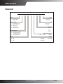
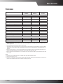
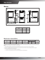
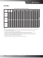
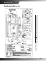
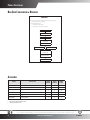
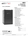
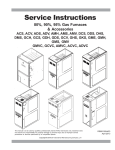
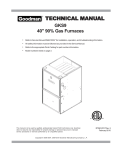
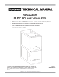
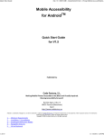
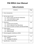
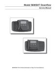
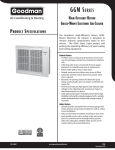
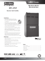
GME8 S eries Multi-Position, Dual$aver Multi-Speed Gas Furnace 80% AFUE Heating Input: 70,000–115,000 BTU/h Standard Features • Dual-diameter tubular heat exchanger • Two-stage gas valve that allows installer to turn on two-stage operation with the flip of a dipswitch • Energy-efficient circulator motor (EEM) • 115V Silicon Nitride igniter designed for long igniter life • Furnace control board with self-diagnostics, color-coded low-voltage terminals, and provisions for electronic air cleaner and 24-volt humidifiers • Control board stores the last five diagnostic codes in memory; simple push-button activation outputs the fault history to a flashing red LED • Low constant fan allows homeowner to activate the low heat speed to efficiently circulate air throughout the home. • Self-adjusting feature automatically adjusts furnace to high- or low-stage operation based on outside temperature without an outdoor temperature sensor • All models comply with California NOx emissions standards Cabinet Features • Fully insulated, heavy-gauge steel cabinet with durable baked-enamel finish • Foil-faced insulation lines the heat exchanger • Designed for multi-position installation: upflow, horizontal left or right • Removable bottom for side- or bottom-return applications • Convenient left or right connection for gas/ electric service • Top gas connection on most models • Coil and furnace fit flush for most installations ™ Contents Nomenclature ................................................................................................... 2 Product Specifications ................................................................................. 3 Dimensions ......................................................................................................... 4 Airflow Data ........................................................................................................ 5 Wiring Diagrams .............................................................................................. 6 Accessories .......................................................................................................... 8 * Complete warranty details available from your local dealer or at www.goodmanmfg.com. To receive the Lifetime Heat Exchanger Limited Warranty (good for as long as you own your home), 10-Year Unit Replacement Limited Warranty and 10-Year Parts Limited Warranty, online registration must be completed within 60 days of installation. Online registration is not required in California or Québec. SS-GME8 www.goodmanmfg.com 11/10 Supersedes 3/10 Product Specifications Nomenclature G M E 8 045 4 B X AA 1 2 3 4,5 6,7,8 9 10 11 12,13 Brand G Goodman® Brand or Dis0nc0ons™ Revisions Major and Minor Revisions Airflow Direc2on C Downflow/Horizontal D Dedicated Downflow H High Airflow K Dedicated Upflow M Upflow/Horizontal Descrip2on/Motor V Two-‐Stage/Variable-‐speed H Two-‐Stage/Mul0-‐speed S Single-‐Stage/Mul0-‐speed E Two-‐Stage/EEM Motor AFUE 95 95% 9 93%+ 8 80% NOx N Natural Gas X Low NOx Cabinet Width A 14” B 17½” C 21” D 24½” 3 1200 Maximum CFM @ 0.5” ESP 4 1600 5 2000 045: 45,000 070: 70,000 090: 90,000 MBTU/h 115: 115,000 140: 140,000 2www.goodmanmfg.com SS-GME8 Product Specifications Specifications GME8 0703BXC* GME8 0905CXC* GME8 1155CXC* 70,000 90,000 115,000 Output¹ 56,000 72,000 92,000 LP Output¹ 48,000 64,000 80,000 80 80 80 Performance Data Input¹ AFUE² Tons AC @ 0.5” ESP 3 5 5 20 - 50 35 - 65 35 - 65 10 X 8 10 X 10 10 X 10 1/2 1 1 Speed 4 4 4 Vent Diameter³ 4 4 4 Temperature Rise Range (°F) Circulator Blower Size (D x W) HP No. of Burners 3 4 5 290 480 480 Min. Circuit Ampacity⁴ 8.2 14.8 14.8 Max. Overcurrent Protection⁵ 15 15 15 Ship Weight (lbs) 130 163 167 Disposable Filter (in²) Electrical Data ¹ ² ³ 4 5 Natural Gas BTU/h: for altitudes above 2,000’, reduce input rating 4% for each 1,000’ above sea level. Low-fire rate is 75% of high-fire rate. DOE AFUE based upon Isolated Combustion System (ICS). Vent diameter may vary depending upon vent length. Refer to the latest editions of the National Fuel Gas Code NFPA 54/ANSI Z223.1 (in the USA) and the Canada National Standard of Canada, CAN/CSA B149.1 and CAN/CSA B142.2 (in Canada). Minimum Circuit Ampacity = (1.25 x Circulator Blower Amps) + ID Blower amps. Wire size should be determined in accordance with National Electrical Codes. Extensive wire runs will require larger wire sizes. Refers to maximum recommended fuse or circuit breaker size; may use fuses or HACR-type circuit breakers of the same size as noted. Notes • All furnaces are manufactured for use on 115 VAC, 60 Hz, single phase electrical supply. • Gas Service Connection ½” FPT • Important: It is required to size overcurrent protection device and wires properly and make electrical connections in accordance with the National Electrical Code and/or all existing local codes. SS-GME8 www.goodmanmfg.com 3 Product Specifications PRODUCT DIMENSIONS Dimensions AMVC8/GMVC8_____X* Alt. Gas Inlet Alt. Gas Inlet Alt. High Voltage High Voltage Inlet Low Voltage Alt. LowVoltage Model GME80703BXA GME80905CXA MODELS GME81155CXA AMVC80704BX** GMVC80704BX** AMVC80905CX** AMVC81155CX** aterialsGMVC80905CX** GMVC81155CX** Minimum Clearances to Combustible M Sides Rear 1 0 A B 17½” 16” 21” A 21” 19½” B 19½” 17-1/2 16 21 19-1/2 All dimensions are in inches. Front Bottom 3 C Vent SW B 6 1 Top 1 C = If placed on combustible floor, the floor MUST be wood ONLY. Notes: • For servicing or cleaning, a 24” front clearance is recommended. • Unit connections (electrical, flue, and drain) may necessitate greater clearances than the minimum clearances listed above. • In all cases, accessibility clearance must take precedence over clearances from the enclosure where accessibility clearances are greater. • Refer to the appropriate USA and Canadian codes: ◊ In the USA: the National Fuel Gas Code NFPA 54 / ANSI Z223.1 ◊ In Canada: the Canada National Standard of Canada, CAN/CSA B149.1 and CAN/CSA B142.2 8 4www.goodmanmfg.com SS-GME8 Product Specifications Airflow Data (CFM & Temperature Rise vs. External Static Pressure) Model GME8 0703BXC* GME8 0905CXC* GME8 1155CXC* Motor Speed Tons AC¹ External Static Pressure, (Inches Water Column) 0.1 CFM 0.2 Rise CFM 0.3 0.4 0.5 Rise CFM Rise CFM Rise CFM Rise 0.6 0.7 0.8 CFM CFM CFM T1 1½ 875 59 793 65 736 70 674 77 592 88 556 509 460 T2 2 1,032 50 965 54 914 57 861 60 810 64 756 712 659 T3 2½ 1,217 43 1,153 45 1,098 47 1,051 49 1,009 51 964 918 877 T4 3 1,365 38 1,313 39 1,268 41 1,221 42 1,172 44 1,129 1,086 1,054 T5 3½ 1,549 33 1,505 34 1,460 36 1,420 37 1,378 38 1,350 1,305 1,268 T1 2½ 1,268 53 1,198 56 1,151 58 1,092 61 1,041 64 988 932 883 T2 3 1,362 49 1,305 51 1,261 53 1,212 55 1,170 57 1,121 1,074 1,021 T3 3½ 1,576 42 1,519 44 1,473 45 1,426 47 1,398 48 1,341 1,290 1,252 T4 4 1,755 38 1,711 39 1,657 40 1,627 41 1,579 42 1,548 1,502 1,463 T5 5 2,183 31 2,128 31 2,094 32 2,060 32 2,014 33 1,992 1,944 1,847 T1 3 1,466 58 1,415 60 1,357 63 1,306 65 1,248 68 1,202 1,144 1,088 T2 3½ 1,642 52 1,596 53 1,552 55 1,499 57 1,449 59 1,388 1,352 1,306 T3 4 1,750 49 1,750 49 1,707 50 1,667 51 1,610 53 1,574 1,531 1,486 T4 4 1,870 46 1,805 47 1,782 48 1,737 49 1,701 50 1,656 1,606 1,571 T5 5 2,297 37 2,297 37 2,224 38 2,106 40 2,014 42 1,896 1,813 1,669 ¹ @ 0.5” ESP Notes • CFM in chart is without filter(s). Filters do not ship with this furnace, but must be provided by the installer. If the furnace requires two return filters, this chart assumes both filters are installed. • All furnaces ship as high-speed cooling and medium-speed heating. Installer must adjust blower cooling and heating speed as needed. • For most jobs, about 375 - 400 CFM per ton when cooling is desirable. • INSTALLATION IS TO BE ADJUSTED TO OBTAIN TEMPERATURE RISE WITHIN THE RANGE SPECIFIED ON THE RATING PLATE. • This chart is for information only. For satisfactory operation, external static pressure should not exceed value shown on the rating plate. • The above chart is for U.S. furnaces installed at 0-2000 feet. At higher altitudes, a properly derated unit will have approximately the same temperature rise at a particular CFM, while ESP at the CFM will be lower. • Factory Motor Speed Setting: T1 = 1st Stage Ht, T2 = 2nd Stage Ht, T5 = Cooling • Tempertaure rise data is based on 2nd-stage heat. First-stage heat is 75% of rise indicated above. SS-GME8 www.goodmanmfg.com 5 Wiring is subject to change. Always refer to the wiring diagram or the unit for the most up-to-date wiring. ⚠ WARNING High Voltage: Disconnect all power before servicing or installing this unit. Multiple power sources may be present. Failure to do so may cause property damage, personal injury, or death. ⚡ Product Specifications Wiring Diagram with Honeywell Valve 6www.goodmanmfg.com SS-GME8 8 Product Specifications ( 6.000 ) Wiring Diagram with White-Rodgers Valve WARNING:DISCONNECT POWER BEFORE SERVICING.WIRING TO UNIT MUST BE PROPERLY POLARIZED AND GROUNDED. INTEGRATED CONTROL MODULE HUMIDIFIER XFMR (6) GND GND (8) 24 VAC HUMIDIFIER C2 MVC (9) HI MVH (12) 9 5 6 1 2 3 WH BL FUSE SEE NOTE 6 BR FS RD RD MANUAL RESET ROLLOUT LIMIT CONTROL(S) (SINGLE CONTROL ON SOME MODELS) 24 VAC XFMR-H HOT SURFACE IGNITER IGN 24V BL CIRCULATOR BLOWER BR 115V WH XFMR WH BK ID BLWR IND COOL-H BK WH LINE-N JUNCTION BOX WH WH YL PRIMARY LIMIT PRESSURE SWITCH YL YL YL WH BK BL WH PM C 1 2 HI 3 GND LINE H FLAME SENSOR STEADY ON = NORMAL OPERATION OFF = CONTROL FAILURE 1 1 FLASH = SYSTEM LOCKOUT (RETRIES/RECYCLES EXCEEDED) 2 FLASHES = PRESSURE SWITCH STUCK CLOSED 3 FLASHES = PRESSURE SWITCH STUCK OPEN 4 4 FLASHES = OPEN HIGH LIMIT 5 5 FLASHES = FLAME SENSE WITHOUT GAS VALVE 6 6 FLASHES = OPEN ROLLOUT OR OPEN FUSE 7 7 FLASHES = LOW FLAME SIGNAL 8 8 FLASHES = CHECK IGNITER OR IMPROPER GROUND C RAPID FLASHES = REVERSED 115 VAC POLARITY/VERIFY GND HI VOLTAGE (115V) HI VOLTAGE FIELD JUNCTION TERMINAL INTERNAL TO INTEGRATED CONTROL PLUG CONNECTION EQUIPMENT GND FIELD GND FIELD SPLICE SWITCH (TEMP.) IGNITER SWITCH (PRESS.) OVERCURRENT PROT. DEVICE NOTES: 1. SET HEAT ANTICIPATOR ON ROOM THERMOSTAT AT 0.7 AMPS. 2. MANUFACTURER'S SPECIFIED REPLACEMENT PARTS MUST BE USED WHEN SERVICING. 3. IF ANY OF THE ORIGINAL WIRE AS SUPPLIED WITH THE FURNACE MUST BE REPLACED, IT MUST BE REPLACED WITH WIRING MATERIAL HAVING A TEMPERATURE RATING OF AT LEAST 105 °C. USE COPPER CONDUCTORS ONLY. 4. BLOWER SPEEDS SHOULD BE ADJUSTED BY INSTALLER TO MATCH THE INSTALLATION REQUIREMENTS SO AS TO PROVIDE THE CORRECT HEATING TEMPERATURE RISE AND THE CORRECT COOLING CFM. (SEE SPEC SHEET FOR AIR FLOW CHART) 5. UNIT MUST BE PERMANENTLY GROUNDED AND CONFORM TO N.E.C. AND LOCAL CODES. 6. TO RECALL THE LAST 5 FAULTS, MOST RECENT TO LEAST RECENT, DEPRESS SWITCH FOR MORE THAN 2 SECONDS WHILE IN STANDBY(NO THERMOSTAT INPUTS). A - 2 INITIAL R www.goodmanmfg.com REV ZONE SS-GME8 ECN 0140F00643 REV. A LOW VOLTAGE (24V) LOW VOLTAGE FIELD 0904051 PK PINK BR BROWN WH WHITE BL BLUE GY GRAY RD RED TO 115 VAC/ 1/60HZ POWER SUPPLY WITH OVERCURRENT PROTECTION DEVICE 3 2 3 COLOR CODES: YL YELLOW OR ORANGE PU PURPLE GR GREEN BK BLACK N 4 ROLLOUT LIMITS (SINGLE CONTROL ON SOME MODELS) GND LINE-N INDUCED DRAFT BLOWER PU L JUNCTION BOX 2 STAGE GAS VALVE PU DISCONNECT BK WH PU 0 WARNING: DISCONNECT POWER BEFORE SERVICING. WIRING TO UNIT MUST BE PROPERLY POLARIZED AND GROUNDED. TO 115VAC/ 1 Ø /60 HZ POWER SUPPLY WITH OVERCURRENT PROTECTION DEVICE BR HOT SURFACE IGNITER DOOR SWITCH C OR RD 5 ( 10.750 ) RD EAC-N LINE-H 24 VAC HUMIDIFIER NO CIR-N ELECTRONIC AIR CLEANER BURNER COMPARTMENT DOOR SWITCH SWITCH LOCATED IN BLOWER COMPARTMENT ON SOME MODELS CIRCULATOR BLWR HI -H AT HE EAC-H BLOWER COMPARTMENT IND-N HE LO AT -H 15 PIN PLUG ON SOME MODELS GR IGN-N INTEGRATED CONTROL MODULE INTEGRATED CONTROL MODULE WH (N) BK BK (HI) BL (MED HI) OR(MED) RD (MED LOW) YL (LOW) PARK RD 6 FP EAC-H BK XFMR-N 115 VAC FLAME SENSOR LO HEAT-H OR PU WH LINE-H RO1 (5) 40 VA TRANSFORMER COOL-H LINE NEUTRAL YL YL 1 XFMR-H AUTO RESET PRIMARY LIMIT CONTROL RO2 (11) BR PU 2 NO C HLO (1) R XFMR (3) BL RD W HI HEAT-H INTEGRATED CONTROL MODULE AUXILIARY LIMITS PS (10) PSO (4) TO MICRO HLI (7) Y ⚡ 12 8 4 G High Voltage: Disconnect all power before servicing or installing this unit. Multiple power sources may be present. Failure to do so may cause property damage, personal injury, or death. 11 7 DLY STG 2N D MODE HT O FF D LY DIAGNOSTIC LED 10 5 MIN 2 STG 100 SEC WARNING Y AUTO 1 STG 150 SEC ⚠ W Wiring is subject to change. Always refer to the wiring diagram or the unit for the most up-to-date wiring. R 7 G ID BLOWER PRESSURE SWITCH AUXILIARY LIMIT CONTROLS 24V THERMOSTAT CONNECTIONS C M1 MVL (2) C GAS VALVE 7 Product Specifications Dual$aver Configuration & Operation Dual$aver™ This furnace is capable of the following heating modes: • Single Stage (Factory Setting) • Modified Two-Stage »» Fixed 5-Min Low Stage »» Auto Time (1-12 Min) Low Stage Start Call for Heat Safety Circuit Check Start Furnace in Low Stage Low-Heat Blower Delay Time (5 Min) or Delay Time (1-12 Min) Gas Valve Switch to 2nd Stage Blower Switch to Hi Heat Operation T-Stat Satisfied Accessories Model Description GME8 0703BX GME8 0905CX GME8 155CX LPM-05 LP Conversion Kit (Springs & Orifice)¹ √ √ √ LPM-06 LP Conversion Kit (Springs & Orifice)² √ √ √ FSRKG-14/17/21/24 Noise Reduction Kits √ √ √ MVK-01³ Masonry Vent Kit √ √ √ HA02 High-Altitude Natural Gas Kit √ √ √ AFE18-60A Fossil Fuel Kit √ √ √ ¹ White-Rodgers valves only ² Honeywell or White-Rodgers valves ³ Upflow applications only Goodman Manufacturing Company, L.P., reserves the right to discontinue, or change at any time, specifications or designs without notice or without incurring obligations. © 2010 • Goodman Manufacturing Company, L.P. • Houston, Texas • Printed in the USA. 8www.goodmanmfg.com SS-GME8