1
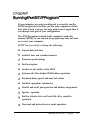
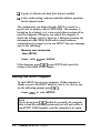
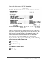
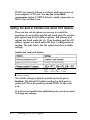
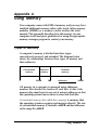
EPSON® PROGRESSION™
Setup Guide
@
This manual is printed on recycled paper and is 100% recyclable.
IMPORTANT NOTICE
DISCLAIMER OF WARRANTY
Epson America makes no representations or warranties, either express or implied, by or
with respect to anything in this manual, and shall not be liable for any implied warranties
of merchantability and fitness for a particular purpose or for any indirect, special or
consequential damages. Some states do not allow the exclusion of incidental or
consequential damages, so this exclusion may not apply to you.
COPYRIGHT NOTICE
All rights reserved. No part of this publication may be reproduced, stored in a retrieval
system, or transmitted, in any form or by any means, electronic, mechanical,
photocopying, recording, or otherwise, without the prior written permission of Epson
America, Inc. No patent liability is assumed with respect to the use of information
contained herein. Nor is any liability assumed for damages resulting from the use of the
information contained herein Further, this publication and features described herein are
subject to change without notice.
TRADEMARKS
Epson is a registered trademark and Epson Progression is a trademark of Seiko Epson
Corporation.
VirtualCache is a trademark of Epson Portland, Inc.
General notice: Other product names used herein are for identification proposes only and
may be trademarks of their respective companies.
Copyright Q 1992 by Epson America, Inc.
Torrance,Califomia
ii
Y74599100200
Important Safety Instructions
1. Read all of these instructions and save them for later reference.
2.
Follow all warnings and instructions marked on the computer.
3.
Unplug the computer from the wall outlet before cleaning. Use a
damp cloth for cleaning; do not use liquid or aerosol cleaners.
4.
Do not spill liquid of any kind on the computer.
5.
Do not place the computer on an unstable cart, stand, or table.
6.
Slots and openings in the cabinet and the back or bottom are
provided for ventilation; do not block or cover these openings.
Do not place the computer near or over a radiator or heat
register.
7.
Operate the computer using the type of power source indicated
on its label. If you are not sure of the type of power available,
consult your dealer or local power company.
8.
If you plan to operate the computer in Germany, observe the
following safety precaution:
To provide adequate shortcircuit protection and over-current
protection for this computer, the building installation must be
protected by a 16 Amp circuit breaker.
9.
Connect all equipment to properly grounded (earthed) power
outlets. If you are unable to insert the plug into an outlet,
contact your electrician to replace your outlet. Avoid using
outlets on the same circuit as photocopiers or air control
systems that regularly switch on and off.
10. Do not allow the computer’s cord to become damaged or frayed.
iii
11. If you use an extension cord with the computer, make sure the
total of the ampere ratings of the devices plugged into the
extension cord does not exceed the ampere rating for the
extension cord. Also, make sure the total of all products
plugged into the wall outlet does not exceed 15 amperes.
12. Do not insert objects of any kind into this product through the
cabinet slots.
13. Except as specifically explained in this manual, do not attempt to
service the computer yourself. Refer all servicing to qualified
service personnel.
14. Unplug the computer from the wall outlet and refer servicing to
qualified service personnel under the following conditions:
A. When the power cord or plug is damaged.
B. If liquid has entered the computer.
C. If the computer does not operate normally when the
operating instructions are followed. Adjust only those
controls that are covered by the operating instructions.
Improper adjustment of other controls may result in
damage and often requires extensive work by a qualified
technician to restore the computer to normal operation.
D. If the computer has been dropped or the cabinet has been
damaged.
E. If the computer exhibits a distinct change in performance.
iv
V
Contents
Introduction
Chapter 1
Setting Up Your System
1 Choosing a Location. . . . . . . . . . . . . . . . . . . . . . . .
2 Removing the Protective Card . . . . . . . . . . . . . . . . . .
3 Connecting a Monitor . . . . . . . . . . . . . . . . . . . . . . .
Using a Display Adapter Card . . . . . . . . . . . . . . . .
4 Connecting a Printer or Other Device . . . . . . . . . . . . .
Using the Parallel Port. . . . . . . . . . . . . . . . . . . . .
Using
SeriaI. . . . . . . . . . . . . . . . . . . . . .
5 connecting the Keyboard. . . . . . . . . . . . . . . . . . . .
6 Connecting the Mouse . . . . . . . . . . . . . . . . . . . . . .
7 Connecting the Power Cord . . . . . . . . . . . . . . . . . . .
8 Turning On the Computer . . . . . . . . . . . . . . . . . . . .
Where To Go Next . . . . . . . . . . . . . . . . . . . . . . . . . .
Chapter 2
1-2
1-3
1-4
1-7
1-8
1-9
1-11
1-12
1-13
1-15
1-16
1-17
Running the SETUP Program
Starting the SETUP Program . . . . . . . . . . . . . . . . . . . .
Selecting Options . . . . . . . . . . . . . . . . . . . . . . . .
Setting the Date and Time . . . . . . . . . . . . . . . . . . . . .
Setting the Processor Speed Options . . . . . . . . . . . . . . .
Setting the Fast Boot Option . . . . . . . . . . . . . . . . . . . .
Setting the System and Video BIOS Options . . . . . . . . . . .
Setting the Keyboard Options . . . . . . . . . . . . . . . . . . .
InstaIled Equipment . . . . . . . . . . . . . . . . . . . . . . . . .
Setting the Built-in Parallel and SeriaI Port Options . . . . . . .
Setting the Speaker . . . . . . . . . . . . . . . . . . . . . . . . .
Setting the Disk Drive Controllers . . . . . . . . . . . . . . . . .
2-2
2-4
2-5
2-6
2-8
2-8
2-10
2-11
2-12
2-14
2-14
Setting the Password Options . . . . . . . . . . . . . . . . . . .
Changing a Password . . . . . . . . . . . . . . . . . . . . .
Deleting a Password. . . . . . . . . . . . . . . . . . . . . .
Setting the Diskette Drive Type(s) . . . . . . . . . . . . . . . .
Setting the Hard Disk Drive(s) . . . . . . . . . . . . . . . . . .
Hard Disk Drive Types . . . . . . . . . . . . . . . . . . . .
Setting the Non-cache Areas . . . . . . . . . . . . . . . . . . . .
Setting the Cache Test and Use Control Options . . . . . . . .
Saving Your Settings and Exiting SETUP . . . . . . . . . . . .
You made changes, and want to save them and
exit SETUP . . . . . . . . . . . . . . . . . . . . . . . .
You made no changes and want to exit SETUP . . . . . .
You made changes and want to exit SETUP
without saving the changes . . . . . . . . . . . . . . .
You saved your settings with [F101 . . . . . . . . . . . .
Post-SETUP Procedures . . . . . . . . . . . . . . . . . . . . . .
Appendix A
2-26
2-26
2-27
2-27
2-29
Using Memory
Types of Memory . . . . . . . . . . . . . . . . . . . . . . . . . .
viii
2-15
2-17
2-17
2-18
2-19
2-19
2-23
2-24
2-25
A-1
®
This manual explains how to set up your Epson Progression™
computer. Chapter 1 provides simple step-by-step instructions
for setting up your system and connecting peripheral devices
such as the monitor, mouse, and printer.
Chapter 2 describes how to run the SETUP program to define
your computer’s configuration. Do this before you use your
computer. If you change the configuration later, you will need
to run it again.
After you set up your system and run SETUP, you can install
your operating system and software. (For general installation
guidelines, see the Read This First card that came with your
system.)
Note
If your computer has already been configured, you don’t
need to run SETUP or install any software. Just set it up as
described in Chapter 1 and turn it on. (Ask your dealer if
you are not sure if your computer was preconfigured.)
For information on using system memory, see Appendix A.
The instructions in this manual are designed to get your system
up and running; for complete information about using your
computer, see the User’s Guide.
If you need help while you are setting up your computer in the
United States, you can contact your dealer or call the Epson
Customer Support Center at (800) 922-8911. If you purchased
your computer outside the United States, contact your nearest
Epson dealer. International Marketing locations are listed
inside the back cover of your User’s Guide.
Chapter 1
Setting Up Your System
To set up your computer, follow the eight steps in this chapter.
You may want to open this manual’s back cover foldout so you
can refer to the illustrations identifying the different parts.
Setting Up Your System
1-1
1
Choosing a Location
When selecting a place to set up your system, choose a safe,
convenient location that provides the following:
0 A flat, hard surface. Surfaces like beds and carpets attract
static electricity, which can erase data on your disks,
damage the computer’s circuitry, and prevent proper
ventilation.
D Good air circulation. Leave several inches of space around
the computer so air can move freely.
D Moderate environmental conditions. Select a cool, dry area
and protect your computer from extremes in temperature,
humidity, dust, and smoke. Avoid direct sunlight or other
sources of heat.
0 No electromagnetic interference. Do not place your system
too close to any electrical device, such as a telephone or
television, which generates an electromagnetic field.
0 Appropriate power cords. Connect all your equipment with
the appropriate power cords for the power source in your
area. If you are operating the computer in a country other
than the one in which you purchased it, see “Power Source
Requirements” in Appendix A of the User’s Guide for
information on the cords you should use.
1-2
Setting Up Your System
2
Removing the Protective Card
If you have only a 3.5-inch diskette drive (one that uses
diskettes that are 3.5 inches wide), go to step 3.
If you have a 5.25-inch diskette drive (like the one shown
below), there may be a protective card in the diskette slot. To
remove it, lift the latch up to release the card; then pull it out.
latch
(If you have a second 5.25-inch diskette drive, be sure to
remove the card from it also.)
Caution
Never turn on your computer with a protective card in the
diskette slot. You could damage the diskette drive.
Save the protective card. If you transport your computer later,
insert the card to protect the drive’s read/write heads during
shipping.
setting up Your system
1-3
3
Connecting a Monitor
The way you connect your monitor to the computer depends
on the type of monitor you have. If you have a VGA monitor
(or a multifrequency monitor with an analog connector), you
can connect it to the computer’s VGA port as described below.
If you have any other type of monitor, see “Using a Display
Adapter Card” on page 1-7.
Note
If a manual was provided with your monitor, refer to those
instructions along with the ones below.
Follow these steps to connect your VGA monitor to the
computer’s VGA port:
1. Place your monitor on top of or near the computer. Turn the
monitor and computer around so the backs are facing you.
2. There should be two cables provided with your monitor: the
monitor cable (to connect it to the computer) and the power
cable (to connect it to a power source). On most monitors,
the monitor cable is permanently attached to the monitor,
such as the one shown in the illustration on the next page.
If your monitor does not have an attached cable, connect
the cable to it now. (See your monitor manual for
instructions.)
1-4
Setting Up Your System
3. Examine the connector end of the monitor cable and position
it to line up with the VGA port on the computer. Then plug
the cable into the port, as shown below.
VGA port
Caution
To avoid damaging the connector, be careful not to bend
the pins when inserting the plug.
4. If the connector has retaining screws, be sure to tighten them.
Setting Up Your System
1-5
5. Plug the monitor power cord into the monitor’s power inlet,
as shown below.
monitor power inlet
6. Plug the other end of the power cord into an appropriate
grounded (earthed) electrical outlet.
1-6
Setting Up Your System
Using a Display Adapter Card
If you are not using a VGA monitor or if you want to install a
display adapter card to control your VGA monitor, read the
guidelines in this section.
Note
Skip this section if you connected your monitor to the
computer’s VGA port.
before you can connect a monitor to a display adapter card, you
must install the card in your computer. If you (or your dealer)
have not already installed it, follow the instructions in
Chapter 3 of the User’s Guide to install an option card.
When installing the card, check to make sure any switches or
jumpers on the card are set properly. For example, you may
need to change a switch setting to select color or monochrome.
See the documentation that came with your monitor and
display adapter card for instructions.
If you install a high-resolution graphics adapter card that
connects to an alternate VGA interface (also called a “feature
connector”), see Chapter 3 of the User’s Guide for instructions
on connecting the card to the feature connector on the main
system board.
Note
If you install a display adapter card, you must set jumper
JP7 on the main system board to disable the built-in VGA
port. (You do not have to do this if you connected the card to
the VGA feature connector on the main system board.) You
may also need to set jumper JP5 to indicate whether you are
using a color or monochrome monitor. See Chapter 3 of the
User’s Guide for instructions on changing jumper settings.
Setting Up Your System
1-7
Once you have installed your adapter card, return to this
section to connect your monitor. If your monitor came with its
own manual, follow the instructions there. Otherwise, you can
follow the steps above for connecting a monitor to the
computer’s VGA port; just insert your monitor connector into
the video card port instead of the computer’s VGA port.
4
Connecting a Printer of Other Device
Your computer has both parallel and serial ports. To connect a
printer or other peripheral device to one of these ports, follow
the instructions below.
1-8
Setting up Your System
Using the Parallel Port
Follow these steps to connect a parallel printer to your
computer:
1. Place the printer next to the computer with their backs facing
you.
2. Position the appropriate end of the printer cable to line up
with the parallel port on the computer, as shown below.
Then plug it in. If the plug has retaining screws, be sure to
tighten them.
parallel port
Setting Up Your System
1-9
3. Connect the other end of the cable to the printer as shown
below. To secure the cable, squeeze the clips at each side of
the printer port and push them into place.
clips
4. Plug the printer’s power cord into an appropriate grounded
(earthed) electrical outlet.
1-10
Setting Up Your System
Using the Serial Port
If you have a serial printer, a modem, or other peripheral
device, you can connect it to the serial (RS-232C) port on the
back of the computer. The serial port uses a DB-9P connector,
so be sure you have a compatible cable.
To connect a serial device, insert the connector into the serial
port, as shown below.
serial port
Note
You need to ensure that the serial port is set up so it
functions properly. If you are using the port for a serial
printer, you need to redirect printer output to the serial port
®
instead of the parallel port. If you’re using MS-DOS , you
can do this with the MODE or SETMODE commands. See
your MS-DOS manuals for instructions.
Setting Up Your System
1-11
5
Connecting the Keyboard
To connect the keyboard, hold the cable connector so the arrow
on the connector faces up. Insert it into the keyboard port, just
to the left of the video port, as shown below.
keyboard port
Caution
Although the connectors and ports for the keyboard and
mouse are physically identical, they cannot be used
interchangeably. Be sure to plug the keyboard into the
keyboard port.
1-12
Setting Up Your System
You can change the angle of the keyboard by adjusting the legs
on the bottom. Turn it over and flip each leg upward until it
locks into place, as shown below.
If you want to lower the keyboard, press down on the recessed
tab (labelled L or R) and lower the leg into the slot.
Connecting the Mouse
®
TM
Your computer has an auxiliary port for an IBM PS/2
compatible mouse that uses a round, miniature DIN (6-pin)
connector. If your mouse has this type of connector, you can
connect it to the built-in port on your computer.
Setting Up Your System
1-13
Note
If you have a mouse that requires a different type of port,
you can connect it to the built-in serial port or install an
appropriate option card to provide the port. You also need
to change the setting of jumpers JP3 and JP4 inside the
computer. See Chapter 3 of the User’s Guide for instructions.
To connect a mouse to the built-in mouse port, plug the
connector into the mouse port as shown below.
mouse port
Caution
Although the connectors and ports for the mouse and
keyboard are physically identical, they cannot be used
interchangeably. Be sure to plug the mouse connector into
the mouse port.
1-14
Setting Up Your System
If your system has not already been configured, you may need
to install a mouse driver. See your mouse manual.
7
Connecting the Power Cord
To connect the computer’s power cord, plug it into the AC
power inlet on the back panel, as shown below.
WARNING
To avoid an electric shock, be sure to plug the cord into the
computer before plugging it into the wall outlet.
power inlet
Plug the other end of the power cord into an appropriate
grounded (earthed) electrical outlet.
Setting Up Your System
1-15
8
Turning On the Computer
After you set up your system, you’re ready to turn on the
power. Follow these steps:
1. Turn your computer around so the front panel faces you and
place your other system components in a convenient
arrangement.
2. Turn on the monitor, printer, and any other peripheral
devices connected to the computer.
3. To turn on the computer, press the power button located on
the right side of the front panel.
power
button
power
indicator
The power indicator below the button lights up. After a
few seconds, the computer displays a count of the system
memory, and then performs its power-on diagnostics. This
is a series of checks the computer runs each time you turn it
on to make sure everything is working correctly.
1-16
Setting Up Your System
4. If necessary, use the controls on your monitor to adjust the
brightness and contrast until characters on the screen are
clear and at a comfortable level of intensity. If your monitor
has horizontal and vertical hold controls, you may need to
use them to stabilize the display.
5. The screen displays the following prompt:
Press <F2> to run SETUP
Do not press any key yet; you just want to make sure the
computer is working. (This prompt appears every time you
turn on your computer so you can run SETUP if necessary.
After a few seconds, the prompt will disappear.)
If there is no operating system installed on your computer,
you then see an error message. Ignore the message for now.
If MS-DOS is already installed on your system, you may see
the command prompt (C : \) or a prompt to enter the date,
or your operating system may load a particular program if
it has been configured to do this.
Where To Go Next
If your system is preconfigured, the only thing you need to do
now is install any additional software and VGA device drivers
you want to use. (See your application program manuals for
instructions on installing software.) If you are using Microsoft@
Windows™ be sure to install the appropriate VGA driver(s) for
your monitor. See the VGA Utilities Guide for instructions.
Then see Chapter 1 of the User’s Guide for important
information about operating your computer.
If your system is not preconfigured, go to Chapter 2 and follow
the instructions there to run the SETUP program. Guidelines at
the end of Chapter 2 tell you what to do next.
Setting Up Your System
1-17
Chapter 2
Running the SETUP Program
If your computer was not preconfigured, you need to run the
SETUP program the first time you use your computer to define
how your system is set up. You may need to run it again later if
you change some part of your configuration.
The SETUP program is stored in the computer’s read-only
memory (ROM), so you can run the program any time you turn
on or reset your computer.
SETUP lets you verify or change the following:
Current date and time
Installed base and extended memory
Processor speed settings
Fast boot option
Location of the built-in video BIOS
System and video shadow RAM address operation
Keyboard delay, speed, and num lock status
Installed equipment information
Parallel and serial port operation and address assignments
Speaker operation
Built-in diskette drive and hard disk drive controller
operation
Password and network server mode operation
Running the SETUP Program
2-1
0 Type(s) of diskette and hard disk drive(s) installed
0 Cache, cache testing, and non-cacheable address operation
for the internal cache.
The configuration you define through SETUP is stored in a
special area of memory called CMOS RAM. This memory is
backed up by a battery, so it is not erased when you turn off or
reset the computer. Whenever you reboot the computer, it
checks the settings, and if it discovers a difference between the
information in the CMOS RAM and its actual hardware
configuration, it prompts you to run SETUP. You see a message
such as the following:
Memory size mismatch
(Run SETUP)
Press <F2> to run SETUP
If this happens, press m to run SETUP and correct the
setting as described in this chapter.
Starting the SETUP Program
To start SETUP, turn on your computer. (If the computer is
already on, press the RESET button to reset it.) As soon as you
see the following prompt, press [
Press
<F2> to run SETUP
Note
If you do not press [F21 within five seconds, the computer
tries to load the operating system and you will not be able to
run SETUP. If this happens, reset the computer to try again.
2-2
Running the SETUP Program
You see the first screen of SETUP information:
[More...
Date/Time
Date:O9/15/1993
Time:13:19:44
<Enter>
to
edit|Use
<+>
or
<->
to
change
There are several screens of SETUP options. A box in the lower
left corner continuously displays the current date and time. The
help lines at the top and bottom of the screen list some of the
keys you can press to perform various SETUP operations.
You can change most of the SETUP options listed in this
chapter; however, the program automatically sets the following
options and you cannot change them:
0 Base memory
0 Extended memory
0 Number of diskette drives
0 Video type.
Running the SETUP Program
2-3
Selecting options
A solid cursor bar highlights the option currently selected. You
can scroll through the options using [II and m When
you reach an option you want to change, press [Mwl to select
+ or I-] to than e
it. The current setting flashes. Then press b
the setting. When the setting is correct, press [tl or d
1 to
go to the next option.
To use the cursor control keys on the numeric keypad, press
CZJ to turn off the num lock function, if necessary.
The table below lists the keys you can use to perform SETUP
operations.
Displays a help screen describing some of the keys you
can use with the program
In]
Displays the date and time prompts so you can set a
new date and/or time
IF11
Sets all the options to the settings last stored In the
CMOS RAM
m
Sets all the options to their default settings
Saves the current configuration settings In your
computer’s CMOS RAM
I
Allows you to save or discard your current settings and
exit the program
I*],[71
Move the cursor to the next or previous option and
highlight it
Move the cursor to the first or last SETUP option and
highlight it
Move the cursor to the first option under the previous or
next heading and display the previous or next heading
that can appear on the screen; also scroll through user
defined non-cache areas In 256KB Increments
2-4
Running the SETUP Program
SETUP key functions (continued)
[Ent#l
Selects the highlighted option so you can change its
setting
EEI
Change the current setting; for numeric parameters,
increases or decreasesthe current numeric value
(3Yizsa
Erases me characters you type for options that require
keyboard entry, such as the date and time
The rest of this chapter describes how to choose the correct
SETUP parameters for your system.
Setting the Date and Time
The real-time clock in your computer continuously tracks the
date and time-even when the computer is turned off. Once
you set the date and time using SETUP, you should not need to
change them, unless you need to adjust the time for daylight
savings or other seasonal adjustments. (The computer
automatically changes the date for leap years.)
To change the date and/or the time, follow these steps:
1. Press [F9). You see the date prompt, such as the following:
Enter the date in mm/dd/yyyy format.
09/15/1993
2. If the entire date is correct, press [Encrl and go to step 5.
If you need to change the date, type two digits for the current
month (mm), such as 09. The cursor moves to the day (dd)
field.
3. Type a two-digit number for the current day (such as 06 or
15). The cursor moves to the year (yyyy) field.
Running the SETUP Program
2-5
4. Type four digits for the year, such as 1993, and press Ibgrl.
(If you make a mistake, press GGCl to erase the
characters before you press @El.)
If you entered an invalid date (such as month 13), you see the
date prompt again. Follow steps 2 through 4 to correct it.
5. Now you see the time prompt:
Enter the time in hh:mm:ss format.
16:03:47
If the time is correct, press @El
If you need to change the time, type the current hour (hh),
then minutes (mm), and then seconds (ss) according to a
24-hour clock. (For example, 5 P.M. would be hour 17.)
Then press IEnl#2 If you make a mistake, press&w
to erase the characters before you press c!h
b
If you entered an invalid time (such as hour 25), you see the
time prompt again. Repeat step 5 to enter a valid time.
You see the date and time you set displayed on the screen,
Setting the Processor Speed Options
There are three processor speed options you can set to
customize your computer’s processing speed. The table below
lists these options and their default settings.
Processor speed options
2-6
Running the SETUP Program
The Auto speed and Power-on low speed options allow
you to set your computer’s processor to operate at one of three
speeds: high, low, and automatic.
High speed is the fastest speed at which your computer’s
processor can operate, such as 25 MHz or 33 MHz; low speed
simulates an 8 MHz processor speed; and automatic speed
switches from high to low speed when your computer accesses
a diskette drive.
At high speed, the processor can access memory faster, so your
programs work faster. Unless you are using an application
program that requires low speed or an older application
program that has specific timing requirements when accessing
diskettes, leave Auto speed and Power-on low speed at
their default settings (disabled). Check your application
program manuals to see if you need to change these settings to
accommodate your programs.
The speed settings you select in SETUP take effect each tune
you turn on or reset your computer. You can also change the
speed temporarily by entering a keyboard command or by
running the ESPEED program, as described in Chapter 1 of the
User’s Guide.
The Software speed change option allows you to disable
the keyboard speed changing commands if they are not
compatible with the application programs you are using. See
Chapter 1 of the User’s Guide for more information.
Note
When the processor is running at high speed, the TURBO
light on the front panel is on; when it runs at low speed, the
TURBO light is off.
Running the SETUP Program
2-7
Setting the Fast Boot Option
The Fast boot option allows you to speed up power-on
diagnostic testing when you turn on or reset your computer.
When you enable Fast boot, your computer does not run
certain system memory tests. The default setting is disabled.
Setting the System and Video BIOS Options
Your computer’s shadow RAM feature copies the contents of
your system and video BIOS ROM (and any external BIOS
ROM you may have installed) into RAM so the computer can
perform certain operations faster.
Your computer enables shadow RAM automatically. However,
there are two SETUP options you can use to control the
memory addresses your computer uses for shadow RAM:
On-board video BIOS location and shadow RAM
areas.
Your video BIOS ROM is located at memory address C000h
(default setting) so you can use your computer with AT
compatible software. If you want to use PS/2 compatible
software, change on-board video BIOS locationto
address E000h.
If you want to control the RAM address areas your computer
uses for shadow RAM, you can enable or disable shadow RAM
for up to twelve 16KB address areas. You may need to do this if
you install an option card, such as a SCSI card, that locates its
RAM in one or more of these areas.
2-8
Running the SETUP Program
The Shadow RAM areas option allows you to enable or
disable shadow RAM in the address ranges listed below. The
default setting for each area is listed in parentheses. (If
necessary, press [ to display the options.)
P C0000h - C3FFFh (Enabled)
0 C4000h - C7FFFh (Enabled)
Q C8000h - CBFFFh (Enabled)
Q CC000h - CFFFFh (Enabled)
Q D0000h - D3FFFh (Disabled)
Q D4000h - D7FFFh (Disabled)
Q D8000h - DBFFFh (Disabled)
Q DC000h - DFFFFh (Disabled)
Q E0000h - E3FFFh (Disabled)
Q E4000h - E7FFFh (Disabled)
Q E8000h - EBFFFh (Disabled)
0 EC000h - EFFFFh (Disabled).
To enable or disable shadow RAM at an address, select the area
and press a or m to change the setting.
Note
Your computer automatically enables shadow RAM in the
address area F0000h through FFFFFh. You cannot disable
shadow RAM in this area.
Running the SETUP Program
2-9
Setting the Keyboard Options
There are four keyboard options available:
0 Keyboard function
0 Keyboard delay
Q Keyboard speed
0 Num Lock status after boot.
The Keyboard function option allows you to change the
Keyboard delay and Keyboard speed option settings. If
Keyboard function is Enabled (the default setting), you can
change the other settings. If Keyboard function is disabled,
the keyboard delay and speed settings are listed as N/A and
you cannot change them. You can change the Num Lock
status after boot setting any time.
The Keyboard delay option allows you to select delay
period between the time you press a key and the tune the
character appears on the screen. You can select a delay of 0, 250,
500, 750, or 1000 ms (milliseconds); the higher the number, the
longer the delay. The default setting is 250 ms, or 1/4 second.
The Keyboard speed option sets the rate at which a character
repeats when you hold down a key. You can select virtually
any speed between 002 and 031 kps (keys per second); the
higher the number, the faster the repeat rate. The default
settingis 020 kps.
The Num Lock status after boot option allows you to
select the initial state of the num lock function when you turn
on or reset your system. You can select ON or OFF; the default
setting is ON.
2-10
Running the SETUP Program
Installed Equipment
SETUP displays information about the following equipment
that it detects in your system under the Installed
equipment heading:
0 Number of diskette drives
Q Video type
Q Math coprocessor.
You cannot change the settings for Number of diskette
drives or Video type. However, you may want to check the
Math coprocessor setting to make sure it matches your
configuration.
The Number of diskette drives installed can be 1 or 2.
You can set the type(s) of diskette drive(s) you have installed
under the Diskette Drives heading. See page 2-19 for more
information.
The Video type can be one of the following:
Q EGA or VGA
P 40 Column Color
Q 80 Column Color
Q Monochrome.
If you are using the built-in VGA port, or if you install an EGA
or VGA display adapter card, SETUP displays EGA or VGA as
the video type. If you install a CGA display adapter card,
SETUP displays either 40 Column Color or 80 Column
Color. SETUP displays Monochrome if you install a
monochrome display adapter card.
Running the SETUP Program
2-11
SETUP may detect a built-in or optional math coprocessor on
your computer’s CPU card. You see Yes at the Math
coprocessor option if SETUP detects a math coprocessor or
No if it does not detect one.
Setting the Built-in Parallel and Serial Port Options
There are two sets of options you can use to control the
operation of your built-in parallel and serial ports: the primary
port options and the I/O address options. The primary port
options are listed under the I/O Ports heading and the I/O
address options are listed under the Port Configuration
heading. The table below lists the options and their available
settings.
Parallel and serial port options
~~
Primary serial l/O address
3F8h - COM1 ‘, 2F8h - COM2,
338h - COM3, 238h - COM4
’ Default setting
The default setting for both the parallel and serial port is
Enabled. The default I/O address setting for both ports is
primary (LPT1 for the parallel port and COM1 for the serial
pm.
If you have not installed any additional ports, you do not need
to change any settings.
2-12
Running the SETUP Program
I
If you install additional parallel or serial ports on one or more
option cards, you may want to reassign the built-in ports or
disable them. Follow these guidelines:
Q If you are using only the built-in port, select Enabled (the
default setting) for the primary port option. Also select the
default I/O address option listed in the table above.
Q If you installed an additional port on an option card but
still want to use the built-in port as your primary port,
select Enabled (the default setting) for the primary port
option. Also select the primary I/O address setting (LPT1
or COM1) for the port’s I/O address option (the default
setting)
P If you installed an additional port that is pre-set as the
primary port (LPT1 or COM1), you can select Enabled for
the primary port option (if you still want to use the built-in
port) or Disabled (if you do not want to use the built-in
port). If you leave the built-in port enabled, you must select
a different I/O address for the port. Select one of the
nondefault settings listed in the table above for the parallel
or serial I/O address options, as necessary.
Cl If you installed two or more additional ports, you can select
Enabled for the primary port option (if you still want to
use the built-in port) or Disabled (if you do not want to
use the built-in port). If you leave the built-in port enabled,
you may want to select a different I/O address for the port
if you do not want to use it as the primary port. You can
select one of the settings listed in the table above for the
parallel or serial I/O address options, as necessary.
Running the SETUP Program
2-13
Note
Be sure to set the jumpers on any parallel or serial port
option card(s) you install to indicate how you want the
port(s) to be assigned. The SETUP options do not assign the
addresses for any port installed on an option card. See the
instructions that came with the card(s) for the correct jumper
settings.
Setting the Speaker
If you want the computer’s built-in speaker to beep during
certain operations you may perform, select Enabled for the
Speaker option (the default setting). If you do not want to
hear the speaker, select disabled.
If you enable the speaker, you can adjust its volume using the
SETVOL utility. See Chapter 1 of the User’s Guide for
instructions.
Setting the Disk Drive Controllers
If you are using the standard drive(s) that came with your
computer, you should set the Internal diskette drive
controller and Internal hard disk drive
controller options to Enabled (the default settings).
However, if you install an option card to provide a controller
for a diskette drive or hard disk drive, select Disabled for the
appropriate controller option(s).
2-14
Running the SETUP Program
Setting the Password Options
The SETUP program lets you set an optional password to
control who can use your system. If you do not want to set a
password for your computer, skip this section.
Once you set a password, you must enter it every time you turn
on or reset your computer. If you do not enter it correctly, you
cannot access your system.
Follow these steps to set a password:
1. Highlight the Password security option and press [En(u).
2. The default setting is Not installed. Press [+I or [-I to
change the setting to Installed.
3. Now highlight the Password option and press m. The
default setting is Not set.
4. Press [F21. You see the following prompt:
Enter Power on Password
5. Type the password you want to use. You can type up to
seven characters using the letter or number keys. For
example, you could enter the following:
123abcd
Do not use characters that require the (sml key, such as %,
@, or #, in your password. The computer does not
distinguish between characters that are produced with the
[sNR1 key and those that are not.
The characters do not appear on the screen. (You can use
l+Gq to correct mistakes.)
6. After you type the password, press m
Running the SETUP Program
2-15
7. You see the prompt Enter Password Again. Type your
password and press [ThePasswordoptionsetting
changes to Set.
Note
Be sure to remember the password you enter or write it
down and keep it in a safe place. If you cannot
remember it, you will not be able to use the computer
the next time you turn it on. If you forget your
password, however, there is a way to access your
system. See “Password Problems” in Chapter 7 of the
User’s Guide for more information.
8. If you will be using your computer as a network server and
want to set your password to operate in a special network
security mode, highlight Network server mode and
press El
Enbr Then press [+1 or a to change the setting
from Not installed to Installed. (See ”Using Your
Computer as a Network Server” in Chapter 1 of the User’s
Guide for information about network server mode.)
Note
To provide complete security, be sure to lock the cover onto
your computer. See Chapter 1 of the User’s Guide for
instructions.
After you set a password, you can change or delete it when you
are using the SETUP program or when you are entering the
password to access your computer. Follow the steps in the
appropriate section below to change or delete an existing
password in SETUP. See Chapter 1 of the User’s Guide for
instructions on entering, changing, and deleting your password
as you access your computer.
2-16
Running the SETUP Program
Changing a Password
If you need to change the password you set, follow these steps:
1. If you are already running SETUP, go to step 2.
If you are not running SETUP, follow the instructions at the
beginning of this chapter to start SETUP.
2. Highlight the Password option and press [En(wl. The current
settingis Set.
3. Press [F2). You see a prompt to enter your old password.
4. Type your old password and press [Mwl.
5. At the next prompt, type a new password and press [Mwl.
6. You see a prompt to reenter your password. Enter your new
password again.
Be sure to save your settings as you exit SETUP to keep your
new password. See page 2-25 for instructions.
Deleting a Password
If you want to delete the password you set and disable
password security, follow these steps:
1. If you are already running SETUP, go to step 2.
If you are not running SETUP, follow the instructions at the
beginning of this chapter to start SETUP.
2. Highlight the password security option and press [En#l.
The current setting is Installed.
Running the SETUP Program
2-17
3. Press m or [-I . You see a prompt to enter your old
password.
4. Type your old password and press [Enbrl. The Password
security option setting changes to Not installed.
Be sure to save your settings as you exit SETUP to keep your
password security changes. See page 2-25 for instructions.
Setting the Diskette Drive Type(s)
Your system came with one diskette drive and you may have
installed another drive of a different size or capacity. The
SETUP program may automatically detect the type(s) of
diskette drive(s) you have installed. Check these settings to
make sure they are correct for your configuration.
The following types may be set for diskette drives A and B:
0 1.44MB, 3.5-inch
Cl 1.2MB, 5.25-inch
0 720KB, 3.5-inch
CI 360KB, 5.25-inch
0 Not installed.
The Number of diskette drives option also displays the
number of drives SETUP detects in your system. See page 2-11
for more information.
2-18
Running the SETUP Program
Setting the Hard Disk Drive(s)
The SETUP program lets you select the type of hard disk
drive(s) installed in your computer. If you have two hard disk
drives, the first one is drive 1 and the second one is drive 2. Be
sure to choose the correct setting for both drives.
Follow these guidelines:
a If your system does not have a hard disk, select Not
installed for drives 1 and 2. If you have only one hard
disk drive, select Not installed for drive 2.
0 If your computer came with an Epson 240MB hard disk
drive (or if you installed this drive yourself), select type 34
for drive 1.
P If you have installed another type of hard disk drive, you
need to select the drive type that matches your drive. See
“Hard Disk Drive Types” below.
Hard Disk Drive Types
If you installed a hard disk in your computer that is not the
standard Epson 240MB drive (type 34), you need to select the
correct type to match your drive.
The following table lists the types of standard hard disk drives
you can use. Check this table and the documentation supplied
with your hard disk to find the correct type number for your
drive. (Your drive’s documentation should list all the
parameters necessary to identify it in this table.) If none of the
types listed matches your drive, see “Defining your own drive
type: below.
Running the SETUP Program
2-19
Hard disk drive types
2-20
Running the SETUP Program
Hard disk drive types (continued)
l
Actual size when formatted may be slightly different than the size listed on
the drive label.
t Hard disk drive supported in translate mode
+ Epson drives
Running the SETUP Program
2-21
Defining your own drive type
If the parameters for your hard disk that are listed in its
documentation do not match any of the types listed in the table
above, you can define your own type. Follow these steps:
1. Highlight the Hard disk 1: or Hard disk 2 : option
and press [Marl
2. Press [nl. You see the following prompt in the middle of
the screen:
Enter number of cylinders on disk
3.
Use the numeric keys along the top of the keyboard or on the
numeric keypad (with the num lock function turned on) to
enter the appropriate value for the number of cylinders on
your hard disk. (If you make a mistake, press t!iFiGG
<to
erase the value before you go to the next step.)
4. Press [Enbr). You see a prompt to enter the number of
cylinder (read/write) heads on the drive.
5. Type the correct value as described in step 3 and press [Enbrl.
6. You see a prompt to enter the number of sectors per track on
the disk. T
the correct value as described in step 3 and
pressdr
m .
You do not enter a value for the drive size; SETUP does this
automatically based on the other parameters.
SETUP displays your hard disk drive type as UD followed by
the parameters you entered.
2-22
Running the SETUP Program
Setting the Non-cache Areas
Your computer automatically caches all of your system
memory except for four of the system defined non-cache
address areas listed in the table below. You can enable or
disable caching in any of six, system Defined Cache
control Areas and also set two additional user Defined
non-cached Areas (also listed in thetable).
Non-cache address areas
Option
Default Setting
System donned areas
A0000h - AFFFFh caching
Disabled
B0000h - BFFFFh caching
Disabled
C0000h - CFFFFh caching
Enabled
D0000h - DFFFFh caching
Disabled
E0000h - EFFFFh caching
Disabled
F0000h - FFFFFh caching
Enabled
User defined areas
l
1st User defined non-cache low
address
0000000h*
1st User defined non-cache high
address
0000000h*
2nd User defined non-cache low
address
0000000h*
2nd User defined non-cache high
address
0000000h*
If you set any user-defined non-cache areas, SETUP automatically sets the
high address at least 4KB higher than the corresponding low address.
Running the SETUP Program
2-23
You may want to disable caching in a certain address area to
avoid any memory conflicts if you install an option card or
other device that uses the same address area.
To change the setting of one or more System Defined
Cache Control Areas, select an address area and press [+I
or I-1 to choose Enabled or Disabled.
To disable caching in one or more User Defined
non-cached Areas, you set the beginning address of the
range in a low address option; then you set the ending address
in the corresponding high address option.
First highlight the low address option and press m Then
press El
+ or [-I to scroll through the addresses in 4KB
On toscrollin256KB
increments; or press m or kl
increments. (You see the corresponding high address option
setting increase at least 4KB higher than the low address.) Once
you set the low address, set the corresponding high address in
the same manner.
Note
You cannot use these SETUP options to cache any RAM you
may have installed on an option card.
Setting the Cache Test and Use Control Options
Using SETUP’, you can enable or disable your computer’s
internal cache (built into the microprocessor). The default
setting for the Internal cache option is Enabled.
You may need to disable the cache if it malfunctions or if you
use timing-loopdependent software that requires a slower
system speed. Check your software documentation to see if this
is necessary.
2-24
Running the SETUP Program
You can also disable power-on diagnostic testing of your cache
if you are receiving cache errors that prevent you from using
your computer. This way, you can perform any steps necessary
to diagnose the problem as you obtain technical assistance. (The
default setting for the POD Internal cache test option is
Enabled.)
Note
Neither of the cache options described in this section affect
your system’s VirtualCache™ feature.
Saving Your Settings and Exiting SETUP
The way in which you exit the SETUP program depends on
whether you have changed the settings of any SETUP options
and whether or not you want to save these changes. For
example, you can do one of the following to exit SETUP:
0 Make no changes and exit
0 Save your changes and exit
0 Not save your changes and exit.
Follow the steps in the appropriate section below to save your
settings and exit SETUP. If you have just run SETUP for the
first time, also be sure to read “Post-SETUP Procedures” at the
end of this chapter for further instructions on setting up your
computer.
Note
You can also save your changes and remain in SETUP by
pressing [ any time you are using the program.
Running the SETUP Program
2-25
You made changes, and want to save them and exit
SETUP
Press m You see the following menu:
Save and Exit
No Save and Exit
Return to Setup
Highlight Save and Exit and press [Mwl The computer
saves your settings in its CMOS RAM and reboots.
To remain in the SETUP program, highlight Return t o
setup and press ~ The exit menu disappears and you see
the current SETUP screen.
You made no changes and want to exit SETUP
Press [ You see the following menu:
Exit Setup
Return to Setup
To exit the program, highlight Exit Setup and press [En(wl.
The computer reboots and tries to load your operating system
from a diskette or your hard disk drive.
To remain in the SETUP program, highlight Return t o
setup and press m The exit menu disappears and you see
the current SETUP screen.
2-26
Running the SETUP Program
You made changes and want to exit SETUP without
saving the changes
Press [ You see the following menu:
Save and Exit
No Save and Exit
Return to Setup
Highlight No Save and Exit and press [M*l. The
computer does not save any changes you made to your SETUP
options. The computer reboots and tries to load your operating
system from a diskette or your hard disk drive.
To remain in the SETUP program, highlight Return to
Setup and press [Mwl. The exit menu disappears and you see
the current SETUP screen.
You saved your settings with (
You can save your changes and remain in SETUP by pressing
[ any time you are using the program. When you press
[, you see a message confirming that your changes are
saved. Press (Enlwl to erase the message and return to SETUP.
The manner in which you exit SETUP after using the [F101
key depends on whether you made any changes to your
settings after pressing c5
F10
If you have made no further changes to your SETUP options
and press [ to exit SETUP, you see the following menu:
No Save and Exit
Return to Setup
Running the SETUP Program
2-27
You do not see the Save and Exit option because you have
already saved the latest chart es to your computer’s CMOS
RAM when you pressed el
FlO . Highlight No Save and
Exit and press b
brcr The computer reboots and tries to load
your operating system from a diskette or your hard disk drive.
If you made additional changes to your settings after you
pressed [F101, press m to exit SETUP. You see the
following menu:
Save and Exit
No Save and Exit
Return to Setup
To save your additional changes, highlight Save and Exit
and press m The computer saves the latest settings in its
CMOS RAM and reboots.
If you do not want to save your additional changes, highlight
No Save and Exit and press m The computer does not
save any changes you made since you pressed p7
F10 .
However, the computer still reboots to so it can use the settings
you saved in your CMOS RAM and then tries to load your
operating system from a diskette or your hard disk drive.
(To remain in the SETUP program, highlight Return to
Setup and press m The exit menu disappears and you see
the current SETUP screen.)
2-28
Running the SETUP Program
Post-SETUP Procedures
If you have just run SETUP for the first time, you now need to
install the operating system on your computer. See your
operating system manuals for instructions.
Note
You may see an error message and a prompt to run SETUP
when your computer is rebooting if it detects a problem in
your SETUP configuration. If so, follow the instructions on
the screen to run SETUP and correct the problem.
You may also see an error message when your computer is
rebooting if you have not installed your operating system on
the hard disk or have not inserted a system diskette in
drive A. If you receive this error message, simply follow the
instructions in your operating system manuals to install the
software on your computer.
After you have installed your operating system, you can install
any software you plan to use. See your application program
manuals for instructions.
If you are going to install Microsoft Windows, be sure to also
install the Windows VGA driver(s) as appropriate for your
monitor. See the VGA Utilities Guide for instructions.
Running the SETUP Program
2-29
Appendix A
Using Memory
Your computer comes with 4MB of memory, and you may have
installed additional memory-either with single inline memory
modules (SIMMs) or a memory card-to increase the total
amount. This appendix describes how the memory in your
computer works and gives guidelines for using the appropriate
memory manager program to control your memory.
Types of Memory
A computer’s memory is divided into three types:
conventional, reserved, and extended. The diagram below
shows the relationships between these types of memory and
their addresses.
Conventional
memory
0
Resewed
memory
64OKB
1MB
Extended
memory
Addresses
128MB
All memory in a computer is managed using addressesnumbers that describe the location of each byte of data. Each
memory chip must have its own set of unique addresses so that
the operating system knows where to store and find data.
Conventional memory (also called base memory) is memory that
the operating system recognizes and manages directly. The size
of conventional memory is limited to 640KB and has addresses
in the range 0 to 640KB.
Using Memory A-1
Reserved memory is memory in the range 640KB to 1MB. The
system enhances its performance by using 256KB of this
memory as shadow RAM. Some of the remaining memory may
be available; see Appendix A of the User’s Guide for information
on how your computer uses this memory.
Extended memory is memory with addresses in the range 1MB to
the maximum system memory, and can be used only by the
following:
Q Certain operating systems, such as OS/2
Q Some MS-DOS interfaces, such as Windows
Cl Some RAM disk programs, such as VDISK
Q Some hard disk caching programs, such as SMARTDRV
Q Certain specially-written, protected mode MS-DOS
applications.
Most MS-DOS commands and application programs cannot use
extended memory directly. They need to use expanded memory.
This type of memory allows some MS-DOS applications to get
around the 640KB limitation. You control expanded memory
with a memory manager, which enables the computer to use
your extended memory as expanded memory.
Most versions of MS-DOS include a standard memory manager
and many application programs come with their own. Once
expanded memory is created, it can be used by MS-DOS
applications written for the Lotus®/Intel®/Microsoft (LIM)
Expanded Memory Specification (EMS), version 4.0.
A-Z Using Memory
You can also purchase separate expanded memory manager
programs, such as QEMM.® However, if you are using
MS-DOS, Windows, and other compatible programs, it is best
to use one of the memory managers that came with your
software because these memory managers have been tested and
proven reliable.
For more information about your system’s memory, see the
“System Memory Map” in Appendix A of the User’s Guide. For
instructions on using your memory manager, see the
documentation that came with it.
Note
Microsoft Windows comes with its own memory manager;
be sure to install it if you use Windows. (See your Windows
documentation for instructions.)
Using Memory A-3
Index
A
AC power inlet, 1-15
Addresses,
I/O, 2-12-13
memory, 2-8 -9, 2-23 -24, A-1 -2
non-cacheable, 2-2, 2-23 -24
Alternate VGA interface, 1-7
Analog connector, 1-4
Application programs, 1-17
Automatic settings, SETUP, 2-3,
2-18
Auto speed, 2-6-7
B
Base memory, 2-1, 2-4, A-1
Battery, 2-2
BIOS,
ROM, 2-1, 2-8 -9
shadow RAM, 2-1, 2-8 -9
system, 2-1, 2-8 -9
video, 2-1, 2-8 -9
Built-in ports, see Port
C
Cache,
areas, 2-23-24
internal, 2-2, 2-24 -25
non-cache areas, 2-23 -24
options, 2-2, 2-24 -25
testing, 2-2, 2-24 -25
virtual, 2-25
Card(s),
memory, A-1
option, 1-4, 1-7 -8, 1-14, 2-14
protective, 1-3
CGA card, 2-13
Changing password, 2-16-17
Choosing location, 1-2
Clock, real-time, 2-5
CMOS RAM, 2-2, 2-4, 2-26, 2-28
Color adapter, 2-11
Color monitor, 1-7
Command prompt, 1-17
COMn, 2-12-13
Configuration, Intro-l, 2-1 -2
Configured system, Intro-l, 1-17
Connecting,
keyboard, 1-12
modem, 1-11
monitor, 1-4 -8
mouse, 1-13-15
power cord(s), 1-2, 1-4, 1-6, 1-10,
1-15
printer, 1-8 -11
serial device, 1-11
Controller,
diskette drive, 2-1, 2-14
hard disk, 2-1, 2-14
Conventional memory, A-1
Coprocessor, 2-11-12
CPU speed, 2-1, 2-6 -7
Cursor bar, 2-4
Cursor control keys, 2-4
Customer Support Center,
Intro-l
D
Date prompt, 2-4-5
Date, setting, 2-1, 2-5 -6
Default settings, 2-4
Defining drive type, 2-22
Deleting password, 2-16-18
Diagnostics, power-on, 1-16, 2-8,
2-25
Disk drive controllers, 2-1, 2-14
Diskette drive,
configuring, 2-18
controller, 2-1, 2-14
Index 1
Diskette drive,
number of, 2-11 -12, 2-18
protective card, 1-3
type(s), 2-2, 2-18
Display adapter, 1-4, 1-7 -8, 2-11
Driver(s), 1-15, 1-17
Drives, see Diskette drive or
Hard disk
E
EGA card, 2-11
Electromagnetic interference, 1-2
Environmental conditions, 1-2
Epson Customer Support Center,
Intro-l
Equipment, installed, 2-1, 2-11 -12
Error messages, 1-17, 2-2, 2-29
ESPEED, 2-7
Exiting SETUP, 2-25 -28
Expanded memory, A-2 -3
Extended memory, 2-1, 2-3, A-1 -2
F
Fast boot, 2-1, 2-8
Feature connector, VGA, 1-7
H
Hard disk,
configuring, 2-19-22
controller, 2-1, 2-14
type(s), 2-2, 2-19 -22
Heads, read/write, 1-3
Help screen, 2-4
Help, where to get, Intro-l
High speed, 2-7
I
Indicator, power, 1-16
Inlet, AC power, 1-15
Installed equipment, 2-1, 2-11 -12
Interfaces, built-in, see Port
Interference, electromagnetic, 1-2
Internal cache, 2-2, 2-24 -25
2
Index
Internal drive controllers, 2-1, 2-14
International marketing locations,
Intro-l
I/O addresses, 2-12-13
I/O ports, 2-12-13
J
Jumper settings, 1-7, 1-14, 2-14
K
Keyboard,
adjusting angle, 1-13
cable, 1-12
connecting, 1-12
delay, 2-1, 2-10
function, 2-10
legs, 1-13
num lock, 2-1, 2-10
options, 2-1, 2-10
port, 1-12, 1-14
speed, 2-1, 2-10
Key delay, 2-1, 2-10
L
Light, power, 1-16
LIM EMS, A-2
Loading operating system, 1-17,
2-26-28
Location, choosing, 1-2
Low speed, 2-6-7
LPTn, 2-12-13
M
Marketing locations, Intro-l
Math coprocessor, 2-11-12
Memory,
addresses, 2-8 -9, 2-23 -24, A-1 -2
base, 2-1, 2-4, A-l
cache, 2-23-24
cards, A-l
CMOS RAM, 2-2, 2-4, 2-26, 2-28
conflicts, 2-24
conventional, A-l
Memory,
count, 1-16
expanded, A-2 -3
extended, 2-1, 2-3, A-1 -2
general information, A-1 -3
LIM EMS, A-2
manager, A-1 -3
map, A-3
RAM, 2-1 -2, 2-8 -9, 2-24, 2-26,
2-28, A-1 -3
reserved, A-1 -2
ROM, 2-1, 2-8
shadow RAM, 2-1, 2-8-9
SIMMs, A-l
types, A-1 -2
Messages, error, 1-17, 2-2,2-29
MODE, 1-11
Modem, connecting, 1-11
Monitor,
brightness, 1-17
cable, 1-4 -5,1-8
color, 1-7
connecting, 1-4 -8
contrast, 1-17
monochrome, 1-7
multifrequency, 1-4
port, 1-4 -8, 2-11
power cord, 1-4, 1-6
VGA, 1-4 -5,1-7-8
Monochrome monitor, 1-7
Mouse,
cable, 1-12, 1-14
connecting, 1-13-15
driver, 1-15
port, 1-12-14
MSDOS, 1-11, 1-17, A-2 -3
Multifrequency monitor, 1-4
N
Network server mode, 2-1, 2-16
Non-cacheable addresses, 2-2,
2-23-24
Number of diskette drives,
2-11 -12, 2-18
Numeric coprocessor, 2-11-12
Num lock, 2-1, 2-10
O
On-board video, BIOS, 2-8
Operating speed, 2-1, 2-6 -7
Operating system,
command prompt, 1-17
installing, Intro-l, 1-17, 2-29
loading, 1-17, 2-26 -28
Option cards, 1-4, 1-7 -8, 1-14, 2-14
OS/2, A-2
Output, redirecting, 1-11
P
Parallel,
cable, 1-9-10
interface, 1-8-10
port, 1-8 -10, 2-1, 2-12-14
primary port, 2-12-14
Password,
changing, 2-16-17
default setting, 2-15
deleting, 2-16-18
network server mode, 2-1, 2-16
options, 2-1, 2-15 -18
power-on, 2-15
problems, 2-16
security, 2-15-18
Index 3
Port,
addresses, 2-12-14
configuration, 2-12
keyboard, 1-12,1-14
monitor, 1-4-8,2-11
mouse, 1-12-14
parallel, 1-8 -10, 2-1, 2-12-14
primary, 2-12-14
serial, 1-11, 1-14, 2-1, 2-12-14
VGA, 1-4 -8, 2-1
Post-SETUP, 2-29
Power,
button, 1-16
cord(s), 1-2, 1-4, 1-6, 1-10, 1-15
indicator, 1-16
light, 1-16
source, 1-2
Power-on diagnostics, 1-16, 2-8,
2-25
Power-on low speed, 2-6-7
Power-on password, 2-15
Precautions, safety, 1-2
Preconfigured system, Intro-l, 1-17
Primary port, 2-12-14
Printer,
connecting, 1-8-11
parallel, 1-8 -10, 2-1, 2-12-14
redirecting output, 1-11
serial, 1-11, 2-1, 2-12-14
Processor speed, 2-1, 2-6 -7
Protective card, 1-3
a
QEMM, A-3
R
RAM, 2-1 -2, 2-8 -9, 2-24, 2-26, 2-28,
A-1 -3
Read only memory, 2-1
Read This First card, Intro-l
Read/write heads, 1-3
Real-time clock, 2-5
Redirecting printer output, 1-11
4
Index
Removing protective card, 1-3
Reserved memory, A-1 -2
ROM, 2-1, 2-8
ROM BIOS, 2-1, 2-8 -9
RS-232C, 1-11
S
Safety precautions, 1-2
Saving SETUP settings, 2-25-28
SCSI card, 2-8
serial,
cable, 1-11
device, connecting, 1-11
interface, 1-11
port, 1-11, 1-14, 2-1, 2-12-14
primary port, 2-12-14
RS-232C, 1-11
SETMODE, 1-11
Setting up system, Intro-l, 1-1-17
SETUP program,
automatic settings, 2-3, 2-18
auto speed, 2-6-7
base memory, 2-1, 2-4
BIOS shadow RAM, 2-1, 2-8 -9
built-in ports, 2-1, 2-12 -14
cache, 2-2, 2-23 -25
clock, real-time, 2-5
CPU speed, 2-1, 2-6 -7
date, 2-1, 2-4 -6
default settings, 2-4
disk drive controllers, 2-14
diskette drive type(s), 2-2, 2-18
display adapter type, 2-11
error message, 2-2, 2-29
exiting, 2-25-28
extended memory, 2-1, 2-3
fast boot, 2-1, 2-8
hard disk controller, 2-14
hard disk drive type(s), 2-2,
2-19-22
help screen, 2-4
high speed, 2-7
interfaces, built-in, 2-12-14
SETUP program,
internal cache, 2-2, 2-14 -15
internal drive controllers, 2-14
I/O addresses, 2-12-14
I/O ports, 2-12-13
keyboard delay, 2-1, 2-10
keyboard function, 2-10
keyboard options, 2-1, 2-10
keyboard speed, 2-1, 2-10
key functions, 2-4
leaving the program, 2-25 -28
low speed, 2-6-7
math coprocessor, 2-11-12
memory, 2-2, 2-4, 2-8 -9, 2-23 -24,
2-26, 2-28
network server mode, 2-1, 2-16
non-cacheable addresses, 2-2,
2-23-24
number of diskette drives,
2-11-152-18
numeric coprocessor, 2-11-12
num lock, 2-1, 2-10
options, selecting, 2-4
parallel port, 2-1, 2-12 -14
password, 2-1, 2-15 -18
post-SETUP procedures, 2-29
power-on low speed, 2-6-7
processor speed, 2-1, 2-6 -7
prompt, 1-17, 2-2
RAM, 2-1 -2, 2-8 -9, 2-24, 2-26,
2-28
real-time clock, 2-5
ROM, 2-1, 2-8
saving settings, 2-25 -28
screen, 2-3
serial port, 2-1, 2-12 -14
shadow RAM, 2-1, 2-8-9
software speed change, 2-6-7
speaker, 2-1, 2-14
starting the program, 1-17, 2-2 -5
system BIOS shadow, 2-1, 2-8 -9
time, 2-1, 2-4 -6
video display adapter, 2-11
SETVOL, 2-14
Shadow RAM, 2-1, 2-8 -9
SIMMs, A-l
SMARTDRV, A-2
software, Intro-l
Software speed change, 2-6-7
Speaker, 2-1, 2-14
Speed,
auto, 2-6 -7
CPU, 2-1, 2-6 -7
ESPEED, 2-7
high, 2-7
keyboard, 2-1, 2-10
low, 2-6-7
operating, 2-1, 2-6 -7
power-on, 2-6-7
processor, 2-1,267
software, 2-6 -7
System,
BIOS shadow, 2-1, 2-8 -9
memory, 1-16, 2-23 -24
memory map, A-3
preconfigured, Intro-l, 1-17
setting up, Intro-l, 1-1-17
System-defined cache control
areas, 2-23-24
T
Time prompt, 2-4, 2-6
Time, setting, 2-1, 2-5 -6
Transporting computer, 1-3
TURBO light, 2-7
Turning on computer, 1-3, 1-16 -17,
2-2
U
Userdefined cache control areas,
2-23-24
Use control option, 2-24-25
Index
5
V
W
VDISK, A-2
VGA (Video graphics array),
alternate interface, 1-7
color, 2-10
device drivers, 1-17
display adapter, 1-4, 1-7 -8, 2-11
feature connector, 1-7
interface, alternate, 1-7
monitor, 1-4 -5, 1-7-8
port, built-in, 1-4 -8
Video BIOS, 2-1, 2-8 -9
Video cards, 1-4, 1-7 -8, 2-11
Video monitor, see Monitor
Video shadow RAM, 2-1, 2-8 -9
Video type, 2-11
VirtualCache, 2-25
Volume, 2-14
Windows, 2-29, A-2 -3
6
Index