1
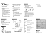
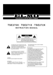
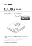
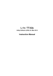
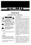
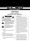
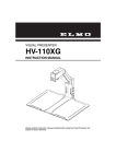
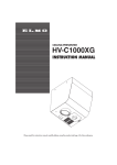
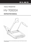
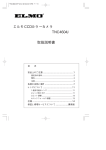
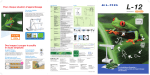
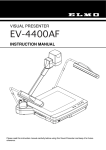
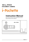
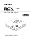
TNC4604
INSTRUCTION MANUAL
CAUTION
RISK OF ELECTRIC SHOCK
DO NOT OPEN
CAUTION : TO REDUCE THE RISK OF ELECTRIC SHOCK.
DO NOT REMOVE COVER (OR BACK).
NO USER SERVICEABLE PARTS INSIDE.
REFER SERVICING TO QUALIFIED SERVICE PERSONNEL.
The lightning flash with arrowhead symbol, within
an equilateral triangle, is intended to alert the user
to the presence of uninsulated "dangerous
voltage" within the product's enclosure that may
be of sufficient magnitude to constitute a risk of
electric shock to persons.
The exclamation point within an equilateral
triangle is intended to alert the user to the
presence of important operating and maintenance
(servicing) instructions in the literature
accompanying the appliance.
CAUTION
• Do not use any power supply other than
specified.
WARNING
TO REDUCE THE RISK OF FIRE OR
ELECTRIC SHOCK, DO NOT EXPOSE
THIS APPLIANCE TO RAIN OR MOISTURE.
* The CAUTION label is attached on the
bottom of camera.
INFORMATION
This equipment has been tested and found
to comply with the limits for Class A digital
device, pursuant to Part 15 of the FCC
Rules. These limits are designed to
provide reasonable protection against
harmful interference when the equipment
is operated in a commercial environment.
This equipment generates, use, and can
radiate radio frequency energy and, if not
installed and used in accordance with the
instruction manual, may cause harmful
interference to radio communications.
Operation of this equipment in a
residential area is likely to cause harmful
interference in which case the user will be
required to correct the interference at his
own expense.
USER-INSTALLER CAUTION: Your
authority to operate this FCC verified
equipment could be voided if you make
changes or modifications not expressly
approved by the party responsible for
compliance to Part of the FCC Rules.
IMPORTANT SAFEGUARDS
1.
Read Instructions
12. Lightning
All the Safety and operating instructions should be
read before the appliance is operated.
2.
For added protection for this video product during a
lightning storm, or when it is left unattended and
unused for long periods of time, unplug it from the
wall outlet and disconnect the power supply and
cable system. This will prevent damage to the video
product due to lightning and power-line surges.
Retain Instructions
The safety instructions and instruction manual
should be retained for future reference.
3.
Heed Warnings
13. Overloading
All warnings on the appliance and in the instruction
manual should be adhered to.
4.
Do not overload power supply and extension cords,
as this can result in a risk of fire or electric shock.
Follow Instructions
14. Object and Liquid Entry
All operating and use instructions should be
followed.
5.
Never push objects of any kind into this video
product through openings as they may touch
dangerous voltage points or short-out parts that
could result in a fire or electrical shock. Never spill
liquid of kind on the video product.
Cleaning
Disconnect this video product from the power
supply before cleaning.
6.
Attachments
15. Servicing
Do not use attachments not recommended by the
video product manufacturer as they may cause
hazards.
7.
Do not attempt to service this video product yourself
as opening or removing covers may expose you to
dangerous voltage or other hazards. Refer all
servicing to qualified service personnel.
Water and Moisture
Do not use this video product near water - for
example, near a bath tub, wash bowl, kitchen sink,
or laundry tub, in a wet basement, or near a
swimming pool and the like.
8.
16. Damage Requiring Service
Disconnect this video product from the power
supply and refer servicing to qualified service
personnel under the following conditions.
a. When the power-supply cord or plug is damaged.
b. If liquid has been spilled, or objects have fallen
into the video product.
c. If the video product has been exposed to rain or
water.
d. If the video product does not operate normally by
following the operating instructions in the
instruction manual. Adjust only those controls that
are covered by the instruction manual as an improper
adjustment of other controls may result in damage
and will often require extensive work by a qualified
technician to restore the video product to its normal
operation.
e. If the video product has been dropped or the
cabinet has been damaged.
f. When the video product exhibits a distinct change
in performance - this indicates a need for service.
Accessories
Do not place this video product on an unstable cart,
stand, tripod, bracket, or table. The video product
may fall, causing serious injury to a child or adult,
and serious damage to the appliance. Use only with
stand, tripod, bracket, or table recommended by the
manufacturer, or sold with the video product. Any
mounting of the appliance should follow the
manufacturer's instructions, and should use a
mounting accessory recommended by the
manufacturer.
9.
Ventilation
This video product should never be placed near or
over a radiator or heat register. This video product
should not be placed in a built-in installation such as
a bookcase or rack unless proper ventilation is
provided or the manufacturer's instructions have
been adhered to.
10. Power Sources
17. Replacement Parts
This video product should be operated only from the
type of power source indicated on the marking label.
If you are not sure of the type of power supply to
your location, consult your appliance dealer or local
power company.
When replacement parts are required, be sure the
service technician has used replacement parts
specified by the manufacturer or that have the same
characteristics as the original part. Unauthorized
substitutions may result in fire, electric shock or
other hazards.
11. Power-Cord Protection
Power-supply cords should be routed so that they are
not likely to be walked on or pinched by items
placed upon or against them, paying particular
attention to cords at plugs, screws, and the point
where they exit from the appliance.
18. Safety Check
-1-
Upon completion of any service or repairs to this
video product ask the service technician to perform
safety checks to determine that the video product is
in proper operating condition.
PART NAMES AND FUNCTIONS
All dimensions in mm (inch)
4
3
1
60 (2.4)
60 (2.4)
8
5
90 (3.5)
2
7
1 Lens mount
Mount a CS-mount lens.
2 Camera mount
For mounting a camera on wall, housing, etc.
(1/4"-20UNC thread)
3 Focusing dial
For fine-adjustment of the lens back-focus.
4 IRIS terminal
Connect when an automatic iris lens is used.
5 VIDEO OUT terminal
Connect to a monitor TV, etc.
(BNC connector)
6 AC power terminal
Connect this to the AC24V 60Hz or DC12V
power supply.
6
+
-
+
DC12V
+
AC24V
1
2
+
-
7 Ground terminal
Connect this to the ground wire of the
power supply cord.
8 Camera control switches
Refer to "CAMERA CONTROLS" on
page 4.
HOW TO CONNECT
1. Before connection, make sure that power of all units are OFF and cords are unplugged.
2. Mount a lens onto the camera. Refer to "HOW TO USE" for usable lens.
3. Connect video terminal of the camera and the video input terminal of a monitor TV, etc. with a
75Ω coaxial cable.
4. Connect the power terminal of the camera to a power supply.
Caution: Installation should be made by a qualified service personnel and should conform to all
local codes.
Lens, coaxial cable for video signal and power supply are not supplied with a camera.
-2-
HOW TO USE
CS-mount
1. Adjust the iris and focus of the lens so that optimum image
may be obtained.
Lens
4mm or less
* Usable lenses
CS-mount lenses, whose length "L" (in the illustration)
L
from the bearing surface of the mount is 4mm or less if
protruded, should be used.
* Using the zoom lens (adjustment of the back focus)
Lens
Camera
The camera is set at the standard back focus position when
shipped from factory. Depending on types of zoom lenses,
however, slight readjustment may be necessary.
Focusing dial
Adjust the lens back-focus by turning the focusing dial in
either direction as per the illustration, referring to the following instructions.
1 Place an object at any fixed distance and set the focus ring of the zoom lens accordingly.
2 Set the zoom lens to full TELE position and obtain the best focus position by turning the
focus ring or the zoom lens.
3 Set the zoom lens to full WIDE position and obtain the best focus position by turning the
focusing dial located on the side of the camera.
4 Repeat procedures 2 and 3 until focus remains constant throughout the zooming range.
Note: When weight of the lens is more than 1kg (2.2lbs), the camera should be supported by the
lens rather than relying on camera mounting screw.
Adjust the back-focus only when necessary.
* Using an auto iris lens
When a DC driven type auto iris lens is used, set the AUTO IRIS switch at DC, and connect the
plug of the lens (for iris terminal) to the IRIS terminal on the right side of the camera.
When a video feedback type auto iris lens is used, set the AUTO IRIS switch at VIDEO, and
connect the plug of the lens (for iris terminal) to the IRIS terminal on the right side of the
camera. (Refer to Lens manual for the level adjustment.)
IRIS terminal
Plug for IRIS terminal
(CHUOMUSEN E4-191J-150)
Soldering side
DC position
1
Control 2
Control +
3
Drive +
4 Drive - (GND)
VIDEO position
+9V iris power (50mA Max.)
GND
0.8Vp-p auto iris video signal
GND
* When a video feedback type auto iris lens (peak/average selectable type) is used at peak
mode, BLC may not function well. In such a case, select the average mode.
2. Before your use of the camera at AES (Automatic Electronic Shutter) mode.
* When using an auto-iris lens, set the AES switch at OFF.
(The AES switch is set at OFF when shipped from factory.)
* The AES mode may increase smears on monitors, which is caused by characteristics of CCD
and is not defect.
Set the AES switch at OFF in case smears appear excessively.
-3-
CAMERA CONTROLS
1 2 3 4
8
6
7
5
1 AGC switch
In case of necessity, set the AGC switch to OFF position.
2 BLC (Black Light Control) switch
With the AGC switch at ON position, BLC are available. In case the back lighting is too bright
to shoot the main object clearly, set this switch to ON position.
3 INT/LL switch
• INT. (internal) control
switch
When the internal
synchronization is used,
set the switch to the INT
side.
Monitor TV
CAMERA
To DC 12V power supply
To AC 24V power supply
Monitor TV
• L.L. (Line-lock) control
Video output
CAMERA
switch
1
Video
Matching the vertical
input
Video switcher
synchronization with
Video output
the power frequency is
called the line-lock.
CAMERA
To AC 24V power supply
2
When the AC24V
power supply is used,
set the switch to the LL side.
When two or more cameras are switched by the video switcher to a monitor TV, the vertical
sync. phase can be locked with the power frequency, and a stable vertical sync. is obtained
without being disturbed at the time of switching.
Caution:
1.The camera is synchronized to the power frequency of 60Hz 0.5Hz covering a normal
fluctuation of the power frequency.
The camera may not compensate for large fluctuation caused by power generated by an
engine generator, etc.
2.It takes about 10 seconds or more to obtain a stable synchronization after the power is
-4-
turned on. This is necessary to stabilize the camera against the power noise.
4 White balance selector
Manual or Automatic white balance modes are selectable. With the setting at AUTO position,
the camera automatically adjusts to the color temperature and adjusts the white balance. The
camera is factory-set at AUTO position. For manual adjustment, set to MANU position and set
the white balance switches as follows.
White balance (WB): According to the combination of the switches 1 and 2, the following
adjustments are available:
*: Can be adjusted by the
1
2
PUSH switch.
AWB
L
L
L
H
H
H
L
H
* Manual (Shift change)
Manual (Fixed 3200k)
Manual (Fixed 4200k)
5 IRIS switch
When a DC driven type auto iris lens is used, set this switch to DC position. When a video
feedback type auto iris lens is used, set this switch to VIDEO position.
6 ALC LEVEL
Adjust video output level, when IRIS switch is DC position.
7 AES switch (Automatic Electronic Shutter)
With the AGC switch at ON position, AES are available.
By setting the AES switch, Automatic Electronic Shutter mode (1/60~1/10,000 sec) is available.
Note: In electronic shutter mode;
*Sufficient brightness is required.
*The picture will flicker when shooting under the illumination produced by fluorescent lamp.
8 PUSH button
• Vertical sync. phase adjustment
Vertical sync. phase adjusting is set at the position fully that the delay time of vertical sync.
phase against the phase of power frequency is shortest, when shipped from the factory.
Select this 8 up ( ) and down ( ) button will make the delay time of vertical sync.
phase against the phase of power frequency longer.
Use the push button 8 if the picture image on a monitor TV may flow when using the
camera in combination with other camera(s) controlled by the Line-Lock synchronization.
In this case, get a proper image by shifting the phase of vertical sync. signal of the camera
against that of the other. If a proper image cannot be obtained even after this adjustment,
reset the potentiometer to its original position, and use the function control potentiometer
8 of the other camera to shift the phase of vertical sync. signal of other camera.
Caution: Before making adjustment, make sure that cameras have their power supplies
connected with the same polarity. (not 180° apart)
• Manual white balance selector
When the white balance selector is set to MANU (shift change) in 4 above, the white
balance can be adjusted by using the PUSH switch. This mode will prove effective under
shooting conditions with little variation in color temperture.
* When the white balance selector is set to MANU (shift change), the vertical sync. phase can
not be adjusted.
-5-
SPECIFICATION
Model
TNC4604
Power source
DC12V (DC11V-35V)
AC24V (AC15V-27V)
60Hz 0.5Hz
Approx.3.5W
Power consumption
Pick-up device
Effective picture element
Scanning area
Scanning system
Scanning frequency (H) (V)
Sync. system
Resolution
Recommended illumination
AGC
White balance
Backlight control
AES
(Automatic Electronic Shutter)
Output signal
Auto-iris terminal
Power terminal
Lens mount
Ambient temperature
Ambient humidity
Dimensions
Weight
Approx.3.7W
1/3"Color interline-transfer CCD
768 (H) x 494 (V)
4.88mm (H) x 3.66mm (V)
2:1 interlaced
15.734kHz 60Hz
Internal
Line-lock/Internal
480 TV lines (Horizontal) 350 TV lines (Vertical)
50 lx (F1.2 under incandescent lamp)
Built-in (Factory-set at ON)
Auto/Manual (Factory-set at AUTO)
Built-in (Factory-set at OFF)
Built-in (Factory-set at OFF)
VBS 1.0 Vp-p, 75Ω, NTSC, compatible
4P (DC/Video)
2P terminal
CS
-10°C ~ +50°C (14°F~122°F)
30% ~ 90%
60 (W) x 60 (H) x 90 (D)mm (2.4 x 2.4 x 3.5 inches)
300grm (0.7lbs)
Note: Weight and dimensions are approximate.
Design and specifications are subject to change without prior notice.
-6-
PRECAUTIONS FOR USE AND INSTALLATION
* Never aim the camera at the sun.
Never aim or point the camera at the sun even
if you are not shooting.
* Do not shoot intense light.
Strong light such as a spot light on the image
plane will cause blooming or smear. When
strong light comes into the image plane,
vertical stripes may appear on it. However,
this does not mean that the camera is defect.
* Take precautions when handling a camera.
Do not drop your camera, or give it a strong
shook or vibration. This may cause camera to
malfunction.
* Do not touch internal parts.
Be sure not to touch the internal parts. This
may cause to electrical shock.
* Do not let the camera get wet.
Install the camera at the place where it will
not get wet.
Should it gets wet, turn off the power
immediately and contact your dealer.
* Install your camera where no video noise
appears.
When camera cables have been laid near
electric wires or television receivers, a noise
may interfere the image.
If noise occurs, relocate cables or reinstall
equipment.
* Check the ambient temperature and humidity.
Avoid using camera in areas where
temperature is consistently hotter or colder
than the specified range (See Specifications
chart below) or poor image quality or
damaged parts may occur. Precautions should
also be taken to avoid areas of high humidity.
* Should you notice any trouble.
If any trouble occurs while you are using the
camera, turn off the camera and contact your
dealer. Failure to do so may cause damage to
the camera.
* The socket-outlet should be installed near the
equipment and should be easily accessible.
ELMO CO., LTD.
6-14, Meizen-cho, Mizuho-ku,
Nagoya, 467-8567 Japan
OVERSEAS SUBSIDIARY COMPANIES
ELMO Mfg. Corp.
ELMO Canada Mfg. Corp.
ELMO (Europe) G.m.b.H.
1478 Old Country Road,
Plainview, NY 11803-5034
U.S.A.
Tel. 516-501-1400
Fax. 516-501-0429
E-mail:elmo@elmousa.com
Web:http://www.elmousa.com/
44 West Drive, Brampton,
Ontario, L6T 3T6,
Canada
Tel. 905-453-7880
Fax. 905-453-2391
E-mail:info@elmocanada.com
Web:http://www.elmocanada.com/
Neanderstr. 18
40233 Dusseldorf,
Germany
Tel. 0211-376051-53
Fax. 0211-376630
E-mail:elmoeurope@AOL.com
Web:http://www.elmo.de/
6X1NHFF02
Printed in CHINA
-7-