1
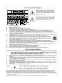
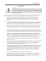
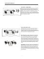
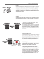
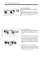
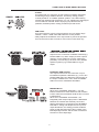
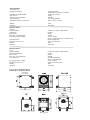
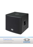
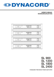
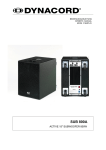
PowerSub 315
1000 WATTS POWERED SUBWOOFER
2x500 WATTS SATELLITE SPEAKER OUTPUTS
Owner‘s Manual | Bedienungsanleitung
INHALTSVERZEICHNIS
WICHTIGE SICHERHEITSHINWEISE
WICHTIGE SERVICEHINWEISE
BESCHREIBUNG
AUSPACKEN & GARANTIE
QUICK START
BEDIENELEMENTE
LEFT INPUT / RIGHT INPUT
LEFT THRU, RIGHT THRU
CLIP LED / SIGNAL LED
X-OVER / SUB LEVEL
LEFT / RIGHT SPEAKER OUTPUT
EXTERNAL SUB OUTPUT
POWER / MAINS IN
SPECIFICATIONS / TECHNISCHE DATEN
DIMENSIONS / ABMESSUNGEN
BLOCK DIAGRAM
SETUP EXAMPLE
.......................
.......................
.......................
.......................
.......................
.......................
.......................
.......................
.......................
.......................
.......................
.......................
.......................
.......................
.......................
.......................
.......................
3
3
4
4
5
6
6
6
6
7
7
7
8
17
17
18
19
CONTENTS
IMPORTANT SAFETY INSTRUCTIONS
IMPORTANT SERVICE INSTRUCTIONS
DESCRIPTION
UNPACKING & WARRANTY
QUICK START
CONTROLS
LEFT INPUT / RIGHT INPUT
LEFT THRU, RIGHT THRU
CLIP LED / SIGNAL LED
X-OVER / SUB LEVEL
LEFT / RIGHT SPEAKER OUTPUT
EXTERNAL SUB OUTPUT
POWER / MAINS IN
SPECIFICATIONS / TECHNISCHE DATEN
DIMENSIONS / ABMESSUNGEN
BLOCK DIAGRAM
SETUP EXAMPLE
2
.......................
.......................
.......................
.......................
.......................
.......................
.......................
.......................
.......................
.......................
.......................
.......................
.......................
.......................
.......................
.......................
.......................
11
11
12
12
13
14
14
14
14
15
15
15
16
17
17
18
19
WICHTIGE SICHERHEITSHINWEISE
Das Blitzsymbol innerhalb eines gleichseitigen
Dreiecks soll den Anwender auf nicht isolierte Leitungen und Kontakte im Geräteinneren hinweisen,
an denen hohe Spannungen anliegen, die im Fall
einer Berührung zu lebensgefährlichen Stromschlägen führen können.
Das Ausrufezeichen innerhalb eines gleichseitigen
Dreiecks soll den Anwender auf wichtige Bedienungs- sowie Servicehinweise in der zum Gerät
gehörenden Literatur aufmerksam machen.
1.
2.
3.
4.
5.
6.
7.
8.
9.
10.
11.
12.
13.
14.
15.
16.
17.
18.
19.
Lesen Sie diese Hinweise.
Heben Sie diese Hinweise auf.
Beachten Sie alle Warnungen.
Richten Sie sich nach den Anweisungen.
Betreiben Sie das Gerät nicht in unmittelbarer Nähe von Wasser.
Verwenden Sie zum Reinigen des Gerätes ausschließlich ein trockenes Tuch.
Verdecken Sie keine Lüftungsschlitze. Beachten Sie bei der Installation des Gerätes stets die entsprechenden Hinweise des Herstellers.
Vermeiden Sie die Installation des Gerätes in der Nähe von Heizkörpern, Wärmespeichern, Öfen oder anderer Wärmequellen.
Achtung: Gerät nur an Netzsteckdose mit Schutzleiteranschluss betreiben. Setzen Sie die Funktion des Schutzleiteranschlusses des
mitgelieferten Netzanschlusskabels nicht außer Kraft. Sollte der Stecker des mitgelieferten Kabels nicht in Ihre Netzsteckdose passen, setzen
Sie sich mit Ihrem Elektriker in Verbindung.
Sorgen Sie dafür, dass das Netzkabel nicht betreten wird. Schützen Sie das Netzkabel vor Quetschungen insbesondere am Gerätestecker und
am Netzstecker.
Verwenden Sie mit dem Gerät ausschließlich Zubehör/Erweiterungen, die vom Hersteller hierzu vorgesehen sind.
Verwenden Sie zusammen mit dieser Komponente nur vom Hersteller dazu vorgesehene oder andere geeignete Lastkarren,
Stative, Befestigungsklammern oder Tische, die Sie zusammen mit dem Gerät erworben haben. Achten Sie beim Transport mittels
Lastkarren darauf, dass das transportierte Equipment und der Karren nicht umfallen und möglicherweise Personen- und/oder
Sachschäden verursachen können.
Ziehen Sie bei Blitzschlaggefahr oder bei längerem Nichtgebrauch den Netzstecker.
Überlassen Sie sämtliche Servicearbeiten und Reparaturen einem ausgebildeten Kundendiensttechniker. Servicearbeiten sind
notwendig, sobald das Gerät auf irgendeine Weise beschädigt wurde, wie z.B. eine Beschädigung des Netzkabels oder des Netzsteckers, wenn
eine Flüssigkeit in das Gerät geschüttet wurde oder ein Gegenstand in das Gerät gefallen ist, wenn das Gerät Regen oder Feuchtigkeit
ausgesetzt wurde, oder wenn es nicht normal arbeitet oder fallengelassen wurde.
Stellen Sie bitte sicher, dass kein Tropf- oder Spritzwasser ins Geräteinnere eindringen kann. Platzieren Sie keine mit Flüssigkeiten gefüllten
Objekte, wie Vasen oder Trinkgefäße, auf dem Gerät.
Um das Gerät komplett spannungsfrei zu schalten, muss der Netzstecker gezogen werden.
Beim Einbau des Gerätes ist zu beachten, dass der Netzstecker leicht zugänglich bleibt.
Stellen Sie keine offenen Brandquellen, wie z.B. brennende Kerzen auf das Gerät.
Dieses SCHUTZKLASSE I Gerät muss an eine NETZ-Steckdose mit Schutzleiter-Anschluss angeschlossen werden.
WICHTIGE SERVICEHINWEISE
ACHTUNG: Diese Servicehinweise sind ausschließlich zur Verwendung durch qualifiziertes Servicepersonal. Um die Gefahr
eines elektrischen Schlages zu vermeiden, führen Sie keine Wartungsarbeiten durch, die nicht in der
Bedienungsanleitung beschrieben sind, außer Sie sind hierfür qualifiziert. Überlassen Sie sämtliche
Servicearbeiten und Reparaturen einem ausgebildeten Kundendiensttechniker.
1.
2.
3.
4.
5.
6.
7.
8.
9.
Bei Reparaturarbeiten im Gerät sind die Sicherheitsbestimmungen nach EN 60065 (VDE 0860) einzuhalten.
Bei allen Arbeiten, bei denen das geöffnete Gerät mit Netzspannung verbunden ist und betrieben wird, ist ein Netz-Trenntransformator zu
verwenden.
Vor einem Umbau mit Nachrüstsätzen, Umschaltung der Netzspannung oder sonstigen Modifikationen ist das Gerät stromlos zu schalten.
Die Mindestabstände zwischen netzspannungsführenden Teilen und berührbaren Metallteilen (Metallgehäuse) bzw. zwischen den Netzpolen
betragen 3 mm und sind unbedingt einzuhalten.
Die Mindestabstände zwischen netzspannungsführenden Teilen und Schaltungsteilen, die nicht mit dem Netz verbunden sind (sekundär),
betragen 6 mm und sind unbedingt einzuhalten.
Spezielle Bauteile, die im Stromlaufplan mit dem Sicherheitssymbol gekennzeichnet sind, (Note) dürfen nur durch Originalteile ersetzt werden.
Eigenmächtige Schaltungsänderungen dürfen nicht vorgenommen werden.
Die am Reparaturort gültigen Schutzbestimmungen der Berufsgenossenschaften sind einzuhalten. Hierzu gehört auch die Beschaffenheit des
Arbeitsplatzes.
Die Vorschriften im Umgang mit MOS-Bauteilen sind zu beachten.
NOTE:
SAFETY COMPONENT (MUST BE REPLACED BY ORIGINAL PART)
Hinweise zur Entsorgung/Wiederverwendung gemäß WEEE
Das auf unserem Produkt und im Handbuch abgedruckte Mülltonnensymbol weist daraufhin, dass dieses Produkt nicht gemeinsam mit dem Haushaltsmüll entsorgt werden darf. Für
die korrekte Entsorgung der Elektro- und Elektronik-Altgeräte (WEEE) am Ende ihrer Nutzungsdauer ist in unserer Kategorie der Hersteller verantwortlich. Aufgrund
unterschiedlicher Regelungen zur WEEE-Umsetzung in den einzelnen EU-Staaten bitten wir Sie, sich an Ihren örtlichen Händler zu wenden. Wir haben ein eigenes System zur
Verarbeitung elektronischer Abfälle und gewährleisten die kostenfreie Entgegennahme aller Produkte der EVI Audio GmbH: Telex, DYNACORD, Electro-Voice und RTS. Wir haben mit
dem Händler, bei dem Sie Ihr Produkt gekauft haben, eine Vereinbarung getroffen, dass alle nicht mehr verwenbaren Geräte zur umweltgerechten Entsorgung kostenfrei an das Werk
in Straubing zurückgeschickt werden.
Bitte kontaktieren Sie vor dem Anschluss an die Spannungsversorgung Ihr Energieversorgungsunternehmen bezüglich Oberwellen.
BESCHREIBUNG
Herzlichen Glückwunsch!
Sie haben sich mit dem PowerSub 315 von Dynacord für einen aktiven Subwoofer modernster Technologie entschieden. Der aktive 15“ Subwoofer PowerSub 315 mit vier integrierten Digitalendstufen mit einer
Gesamtleistung von 2000W wurde speziell zum schnellen und einfachen Aufbau von Subwoofer-Satelliten-Systemen entwickelt.
Bei Subwoofer-Satellitensystemen wird normalerweise ein Center Subwoofer und jeweils eine Satellitenbox links und rechts eingesetzt. Der PowerSub 315 von DYNACORD verfügt aber zusätzlich über einen
Ausgang für einen externen Subwoofer und kann deshalb problemlos auch in aktiven Stereoanwendungen mit bis zu zwei externen zusätzlichen Subwoofern eingesetzt werden.
Als Satellitenboxen werden bevorzugt DYNACORD D 12 12‘ 2-Weg Boxen empfohlen. Es können aber
jederzeit auch andere geeignete Satellitenboxen eingesetzt werden weil der PowerSub 315 eine umschaltbare aktive Frequenzweiche enthält. Die Anpassung auf kleinere oder grössere Satellitenboxen,
z.B. DYNACORD LM 8-2 oder F150 ist mit dem umschaltbaren X-Over problemlos möglich.
Insgesamt können an den PowerSub 315 bis zu vier 8 Ohm Satellitenboxen und bis zu zwei zusätzliche
passive 8 Ohm Subwoofer, z.B. DYNACORD SUB 115 angeschlossen werden.
Die Endstufenleistungen werden, beim Umschalten der Betriebsart mit dem ‚MODE‘ Schalter auf der
Rückseite, automatisch auf die angeschlossenen Boxen aufgeteilt.
Vier Rollen und zwei Tragegriffe sowie ein eingebauter Hochständerflansch ermöglichen einen bequemen Transport und einfachste Aufstellung sowohl von Center Subwoofer Systemen als auch Stereo Satellitensystemen.
Auspacken und Garantie
Öffnen Sie die Verpackung und entnehmen Sie den PowerSub 315. Es liegt noch zusätzlich zu dieser
Bedienungsanleitung ein Netzkabel und die Garantiekarte bei. Überprüfen Sie bitte, ob die Garantiekarte
vollständig ausgefüllt ist, denn nur so können Sie etwaige Garantieansprüche geltend machen. Bewahren
Sie zur Garantiekarte auch den Kaufbeleg auf.
Aufstellen und Anschließen
Stellen Sie den PowerSub 315 mit den dafür vorgesehenen Gummifüßen auf eine ebene Unterlage, so
dass immer eine sichere und standfeste Arbeitslage gewährleistet ist. Kontrollieren Sie bei Anwendungen
mit Hochständerstangen im PowerSub 315 die Stabilität des Systems und sichern Sie die Kabinette mit
zusätzlichen Sicherungsgurten gegen Umfallen.
Die Geräterückseite darf im Betrieb nicht abgedeckt werden. Der PowerSub 315 kann ansonsten durch
thermische Überlastung in den Powerreductions-Mode schalten. Das Gerät nimmt dadurch zwar keinen
Schaden, aber die volle Ausgangsleistung steht nicht mehr zur Verfügung. Die Netzspannung wird über
das professionelle “PowerCon” Steckersystem von Neutrik und einem extra langen, hochflexiblen Netzkabel (5m) realisiert. Diese Anschlußart stellt eine absolut betriebssichere Verbindung zur Netzversorgung
her. Bei größeren Systemen mit mehreren aktiven Kabinetten ist unbedingt darauf zu achten, dass nur
hochwertige Netzverteiler mit ausreichender Strombelastbarkeit und entsprechender Absicherung zur
Anwendung kommen.
Vor dem erstmaligen Anschließen ans Netz stellen Sie bitte sicher, dass die am Kabinett aufgedruckte Betriebsspannung der örtlichen Netzspannung entspricht.
4
QUICKSTART
QUICKSTART
Achtung:
Nach dem Aufbau der Anlage schalten Sie zuerst das Mischpult ein und schieben
Sie die Masterfader am Mischpult auf den untereren Anschlag. Anschliessend
können Sie den PowerSub 315 einschalten und mit den Ausgangsfadern die gewünschte Lautstärke einstellen. Ungewollt könnten Sie sonst bei eingeschalteter
Signalquelle sehr hohen Schallpegeln ausgesetzt werden, die zu Gehörschädigungen führen könnten.
Diese Quickstart-Anleitung erklärt Aufbau und Betrieb eines PowerSub 315 als Subwoofer Satelliten-Anlage
mit einem DYNACORD CMS 1000 oder CMS 1600 Mischpult (siehe Aufbaubeispiele Seite 19-20).
1.
Stellen Sie Ihre Satellitenboxen, z.B. DYNACORD D 12, links und rechts auf Hochständer. Die
Boxenunterkanten sollten in etwa 1m Höhe über dem Publikum sein um eine genügende
Reichweite zu erzielen und die in der Nähe befindlichen Zuhörer vor zu hohen Schallpegeln zu
schützen.
2.
Stellen Sie den PowerSub 315 zwischen die Satelliten-Boxen und verbinden Sie die Satellitenboxen
mit einem geeigneten SPEAKON Lautsprecherkabel mit den Buchsen ‚LEFT SATELLITE SPEAKER
OUTPUT‘ und ‚RIGHT SATELLITE SPEAKER OUTPUT‘ an der Rückseite des PowerSub 315.
3.
Verbinden Sie die Master Outputs Ihres Mischpultes, z.B. DYNACORD CMS 1000, mit geeigneten
XLR Kabeln mit den Buchsen ‚LEFT INPUT‘ bzw. ‚RIGHT INPUT‘ am PowerSub 315 und schieben
Sie die Masterfader am Mischpult auf den unteren Anschlag. Schalten Sie nun das Mischpult ein.
4.
Sie können nun den PowerSub 315 mit dem beiliegenden PowerCon Netzkabel an das Stromnetz
anschliessen. Der blaue PowerCon Stecker wird hierzu in die blaue ‚Mains In‘ Buchse gesteckt und
durch Drehung verriegelt. Mit dem roten ‚Power On‘ Schalter setzen Sie den PowerSub 315 in Betrieb.
5.
Schliessen Sie nun ein Mikrofon an den 1. Eingangskanal Ihres Mischpultes, z.B. CMS 1000 an.
Stellen Sie alle Drehregler in Mittelstellung. Sprechen oder singen Sie laut in das Mikrofon und
justieren den ‚Gain‘ Regler im Kanal so, daß die grüne ‚SIGnal‘ LED aufleuchtet. Die rote ‚PeaK‘ LED
sollte nicht oder nur gelegentlich aufleuchten. Die rote LED zeigt an daß im Kanal bereits
Verzerrungen auftreten. Hierbei kann nichts kaputtgehen, der Klang ist aber sehr störend verzerrt.
6.
Sie können nun den Kanalfader und die Masterfader am Mischpult langsam auf die gewünschte
Lautstärke ‚hochfahren‘.
7.
Die klangliche Balance zwischen Bass und Mittel-Hochtonbereich stellen Sie nun mit dem Regler ‚SUB
LEVEL‘ am PowerSub 315 ein. Diese Justierung kann auch gut mit einem CD Player gemacht
werden. Der CD Player muss natürlich an die ‚LINE‘ Inputs‘ oder über die ‚2TRACKRET‘ Cinch
Buchsen am CMS 1000 Mischpult angeschlossen werden.
8.
Ihre Anlage ist nun betriebsbereit und Sie können individuell notwendige klangliche Korrekturen in den
Eingangskanälen des Mischpultes justieren. Falls starke Bassanhebungen oder Bassabsenkungen
in den Eingangskanälen notwendig sein sollten, korrigieren Sie den ‚Sub Level‘ am PowerSub 315.
In den Eingangskanälen des Mischpultes sollten nur moderate Einstellungen der Klangregler
vorkommen. Extreme Einstellungen sind ein Indiz für eine falsche Justierung des ‚SUB LEVEL‘ im
PowerSub 315.
9.
Nun viel Spass beim Arbeiten mit Ihrer PowerSub 315 Satellitenanlage!
10.
Nach Benutzung schalten Sie zuerst den PowerSub 315 und anschliessend Ihr Mischpult aus.
Störende Abschaltgeräusche können dann nicht auftreten. Bei Verwendung eines DYNACORD CMS
Mischpultes treten an den ‚Master Outputs‘ keinerlei Abschaltgeräusche auf, hier können Sie
bedenkenlos auch das Mischpult zuerst ausschalten.
5
BEDIENELEMENTE
LEFT INPUT , RIGHT INPUT
Elektronisch symmetrische Eingänge zum Anschluss
an hochpegelige Signalquellen wie z.B. Mischpultausgänge. Der Anschluß kann dabei wahlweise über
Klinken- oder XLR-Stecker vorgenommen werden. Um
etwaigen externen Brumm-, oder Hochfrequenzeinstreuungen vorzubeugen, sollte die Signaleinspeisung
bevorzugt über hochwertige abgeschirmte Audiokabel
mit XLR-Steckern erfolgen.
LEFT THRU, RIGHT THRU
Diese Buchsen sind mit den zugehörigen XLR Eingangsbuchsen direkt parallel verbunden und zum
“Weiterschleifen” der Eingangssignale gedacht. Ein
weiterer PowerSub 315 kann beispielsweise direkt von
diesen Buchsen aus angesteuert werden.
Die CLIP LED zeigt beim Aufleuchten an, daß der
interne Leistungsverstärker aktuell im Grenzbereich
der Aussteuerbarkeit betrieben wird. Kurzzeitiges
Aufleuchten ist unkritisch, da der Audio-Limiter im
Leistungsverstärker die Verzerrungen ausregelt und
dadurch das Klangbild erhalten bleibt. Dauerndes Aufleuchten deutet auf eine Übersteuerung der Eingangssektion hin, die zu Klangeinbußen führen könnte und
durch Absenkung der Lautstärke vermieden werden
sollte.
Die SIGNAL LED zeigt an, dass ein Audiosignal am
Eingang anliegt. Falls kein Bass zu hören ist steht der
SUB Levelregler vermutlich auf Linksanschlag und
sollte bis zur Mittelrastung aufgedreht werden. Falls
aus den Satellitenboxen kein Audiosignal zu hören ist,
sind vermutlich die Lautsprecherleitungen nicht richtig
angeschlossen.
6
BEDIENELEMENTE
X-OVER
Mit diesem Schalter können Sie die Trennfrequenz zwischen dem Subwoofer und den Mittel-Hochton Satellitenboxen verändern. Die Werkseinstellung ist 100Hz und besonders für 12“ Satellitenboxen geeignet.
Für Topteile mit 10“ oder 8“ Lautsprechern ist die 160Hz Einstellung
vorteilhaft um eine mechanische Überlastung der kleinen Membranen zu
vermeiden. Für Topteile mit 15“ Lautsprechern bietet die 80Hz Position
häufig klangliche Vorteile.
SUB LEVEL
Mit diesem Regler stellen Sie die Lautstärke des PowerSub 315 ein. Der
Einstellbereich erstreckt sich dabei von -∞dB bis +10dB mit 0dB in Mittelstellung.
Der ‚SUB LEVEL‘ Regler sollte immer so justiert werden daß am Mischpult nur geringfügige Korrekturen der Bass Klangregler eingestellt werden müssen.
LEFT SATELLITE SPEAKER OUTPUT, RIGHT
SATELLITE SPEAKER OUTPUT
Hier werden die Satelliten-Boxen, z.B. DYNACORD
D 12 angeschlossen. Jeder dieser Ausgänge kann
bis zu 500W Leistung an 4 Ohm liefern. An jedem
Ausgang können also bis zu zwei 8 Ohm Satellitenboxen, z.B. je zwei DYNACORD D 12 angeschlossen werden.
EXTERNAL SUB OUTPUT
An dieser Buchse können ein oder zwei zusätzliche
passive Subwoofer angeschlossen werden, z.B. ein
oder zwei DYNACORD SUB 115. Die maximale Ausgangsleistung an dieser Buchse beträgt 500W an 4
Ohm, der MODE SWITCH muss hierzu auf die Stellung ‚INTERNAL+EXTERN‘ geschoben werden.
MODE SWITCH
In der Stellung ‚INTERNAL SUB ONLY‘ wird nur der
eingebaute Subwoofer benutzt und mit 1000W /
8 Ohm betrieben. Die ‚EXTERNAL SUB OUTPUT‘
Buchse ist in dieser Position abgeschaltet.
In der Stellung ‚INTERNAL+EXTERN‘ wird die
Leistung der eingebauten Endstufen zwischen dem
eingebauten Subwoofer und den extern angeschlossenen passiven Subwoofern aufgeteilt. Durch die
insgesamt grössere Membranfläche und geringere
mechanische Auslenkung der Membranen ergibt
sich trotz Leistungsaufteilung, in dieser Betriebsart
ein etwas höherer Gesamtschalldruck als in der
Stellung ‚INTERNAL SUB ONLY‘.
7
BEDIENELEMENTE
POWER
Netzschalter zum Ein- und Ausschalten des Gerätes. Der Netzschalter ist beleuchtet,
wenn der PowerSub 315 eingeschaltet ist. Sollte der Schalter nach dem Einschalten nicht
leuchten, prüfen Sie zuerst ob das Netzkabel angesteckt und verriegelt ist. Ist dies der Fall
und trotzdem keine Funktion vorhanden, kontaktieren Sie bitte ihren Fachhändler.
MAINS IN
Der netzseitige Anschluß ist mit einer PowerCon-Buchse ausgeführt. Ein 5m langes
Netzkabel mit PowerCon-Stecker ist im Lieferumfang enthalten. Beim Einstecken des PowerCon Steckers muss der Stecker durch eine Viertelumdrehung nach rechts verriegelt
werden. Beim Abstecken muss die verchromte Betätigungslasche am Stecker mit dem
Daumen nach hinten gezogen werden und der Stecker kann mit einer Vierteldrehung wieder vom Gerät abgenommen werden.
8
Notes
CONTENTS
IMPORTANT SAFETY INSTRUCTIONS
IMPORTANT SERVICE INSTRUCTIONS
DESCRIPTION
UNPACKING & WARRANTY
QUICK START
CONTROLS
LEFT INPUT / RIGHT INPUT
LEFT THRU, RIGHT THRU
CLIP LED / SIGNAL LED
X-OVER / SUB LEVEL
LEFT / RIGHT SPEAKER OUTPUT
EXTERNAL SUB OUTPUT
POWER / MAINS IN
SPECIFICATIONS / TECHNISCHE DATEN
DIMENSIONS / ABMESSUNGEN
BLOCK DIAGRAM
SETUP EXAMPLE
10
.......................
.......................
.......................
.......................
.......................
.......................
.......................
.......................
.......................
.......................
.......................
.......................
.......................
.......................
.......................
.......................
.......................
11
11
12
12
13
14
14
14
14
15
15
15
16
17
17
18
19
IMPORTANT SAFETY INSTRUCTIONS
The lightning flash with arrowhead symbol, within an equilateral
triangle is intended to alert the user to the presence of uninsulated
”dangerous voltage” within the product’s enclosure that may be of
sufficent magnitude to constitute a risk of electric shock to persons.
The exclamation point within an equilateral triangle is intended to
alert the user to the presence of important operating and
maintance (servicing) instructions in the literature accompanying
the appliance.
1.
2.
3.
4.
5.
6.
7.
8.
9.
10.
11.
12.
13.
14.
15.
16.
17.
18.
19.
Read these instructions.
Keep these instructions.
Heed all warnings.
Follow all instructions.
Do not use this apparatus near water.
Clean only with a dry cloth.
Do not cover any ventilation openings. Install in accordance with the manufacturer’s instructions.
Do not install near heat sources such as radiators, heat registers, stoves, or other apparatus (including amplifiers) that produce heat.
Do not defeat the safety purpose of the polarized or the grounding-type plug. A polarized plug has two blades with one wider than the other. A grounding type
plug has two blades and a third grounding prong. The wide blade or the third prong are provided for your safety. If the provided plug does not fit into your outlet, consult an electrician for replacement of the obsolete outlet.
Protect the power cord from being walked on or pinched particularly at plugs, convenience receptacles, and the point where they exit from the apparatus.
Only use attachments/accessories specified by the manufacturer.
Use only with the cart, tripod, bracket, or table specified by the manufacturer, or sold with the apparatus. When a cart is used, use caution
when moving the cart/apparatus combination to avoid injury from tip-over.
Unplug this apparatus during lightning storms or when unused for a long period of time.
Refer all servicing to qualified service personnel. Servicing is required when the apparatus has been damaged in any way, such as powersupply cord or plug is damaged, liquid has been spilled or orbjects have fallen into the apparatus, the apparatus has been exposed to rain or
moisture, does not operate normally, or has been dropped.
Do not expose this equipment to dripping or splashing and ensure that no objects filled with liquids, such as vases, are placed on the equipment.
To completely disconnect this equipment from the AC Mains, disconnect the power supply cord plug from the AC receptacle.
The mains plug of the power supply cord shall remain readily operable.
No naked flame sources, such as lighted candles, should be placed on the apparatus.
The product should be connected to a mains socket outlet with a protective earthing connection.
IMPORTANT SERVICE INSTRUCTIONS
CAUTION: These servicing instructions are for use by qualified personnel only. To reduce the risk of
electric shock, do not perform any servicing other than that contained in the Operating Instructions
unless you are qualified to do so. Refer all servicing to qualified service personnel.
1.
2.
3.
4.
5.
6.
7.
8.
Security regulations as stated in the EN 60065 (VDE 0860 / IEC 65) and the CSA E65 - 94 have to be obeyed when servicing the appliance.
Use of a mains separator transformer is mandatory during maintenance while the appliance is opened, needs to be operated and is connected to the mains.
Switch off the power before retrofitting any extensions, changing the mains voltage or the output voltage.
The minimum distance between parts carrying mains voltage and any accessible metal piece (metal enclosure), respectively between the mains poles has to
be 3 mm and needs to be minded at all times. The minimum distance between parts carrying mains voltage and any switches or breakers that are not connected to the mains (secondary parts) has to be 6 mm and needs to be minded at all times.
Replacing special components that are marked in the circuit diagram using the security symbol (Note) is only permissible when using original parts.
Altering the circuitry without prior consent or advice is not legitimate.
Any work security regulations that are applicable at the locations where the appliance is being serviced have to be strictly obeyed. This applies also to any
regulations about the work place itself.
All instructions concerning the handling of MOS-circuits have to be observed.
NOTE:
SAFETY COMPONENT (MUST BE REPLACED BY ORIGINAL PART)
WEEE RECYCLING/DISPOSAL INSTRUCTIONS
The Wheelie Bin symbol found on the product or in the manual indicates that this product must not be disposed of with other waste. It is in our category the
manufacturer’s responsibility to properly dispose of their waste electrical and electronic equipment (WEEE) at the end of its life. Due to the differences in each EU
country’s management of WEEE, please contact your local distributor. We are committed to facilitate our own electronic-waste-management-system, for the free
of charge return of all EVI Audio GmbH products: Telex, DYNACORD, Electro-Voice and RTS. Arrangements are made with the dealer where you purchased the
equipment from, for the returning of all unusable equipment at no cost, to the factory in Straubing, for environmental protective disposal.
Due to line current harmonics, we recommend that you contact your supply authority before connection.
DESCRIPTION
Congratulations!
With buying a Dynacord PowerSub 315 you have chosen a state-of-the-art active subwoofer that
employs most advanced technology. The active 15” subwoofer PowerSub 315 with four integrated digital
power amps provides total output power of 2000W and has been designed for the quick and easy set-up
of subwoofer satellite systems.
Subwoofer satellite systems normally employ a center woofer system and satellite cabinets on the
left and right sides. DYNACORD’s PowerSub 315 provides an additional output for the connection of
external subwoofers, for it to be equally used in active stereo applications employing up to two additional
external subwoofers.
While using DYNACORD D 12 12” 2-way systems as satellite cabinets is recommended, the PowerSub
315’s switch able integrated active crossover allows matching the PowerSub 315 to smaller or bigger
satellite systems (e.g. DYNACORD LM 8-2 or F150) or to any other suitable speaker system.
The PowerSub 315 offers connection for a total of up to four 8 ohms satellite speakers and up to two
additional passive 8 ohms subwoofers (e.g. DYNACORD SUB 115).
Power amp output capacity is automatically distributed to the connected speaker systems when
switching between operation modes using the ‚MODE‘ switch on the rear of the appliance.
Four castors, two carrying handles and an integrated pole-mount stand flange facilitate transport and
set-up of center subwoofer and stereo satellite systems.
Unpacking and Warranty
Carefully open the packaging and take out the PowerSub 315. Next to the PowerSub itself, the package
also includes this owner’s manual, a mains cord and the warranty certificate. Make sure that all
information on the warranty certificate is correctly filled in. Only a completed warranty certificate entitles
you to file any claims. Keep the original invoice, which states the purchase/delivery date together with
the warranty certificate at a safe place.
Installation and Connection
Install the PowerSub 315 with its rubber stands on an even ground to ensure stable and secure
operation. For applications with pole-mounts inserted in the PowerSub 315, inspect the stability of the
entire system and use additional ropes to secure the cabinets from falling over.
Do not cover the rear panel during operation. Otherwise, because of thermal overload, the PowerSub
315 may enter reduced power mode, which protects the PowerSub from being damaged while on
the hand full output power is not available. Mains connection is provided via Neutrik’s professional
“PowerCon” connector system and an extra long (5m), highly flexible mains cord offering absolute
safe operation. With bigger system set-ups consisting of several active cabinets, the use of quality
mains distribution hardware throughout the entire installation, being appropriate to handle total power
consumption and providing sufficient fuse protection, is absolutely mandatory.
Before establishing mains connection for the first time or after changing locations, make sure to
examine the mains voltage label to ensure that the power specifications of the local mains match
those of the PowerSub 315.
12
QUICKSTART
QUICKSTART
Caution:
After system installation is complete, make sure to first power on the mixing
console and to position the master faders at their lowest setting before switching
the power of the PowerSub 315 to On. Use the output faders to establish the
desired volume setting. Otherwise, switching and power-on noise or the high level
audio signal of an inadvertently playing audio source could result in high acoustic
outputs, that in some cases might even lead to hearing damage.
This quick-start manual explains installation and operation of a PowerSub 315 subwoofer satellite system used
together with a DYNACORD CMS 1000 or CMS 1600 mixer (see ‘installation examples’ on page 19-20).
1.
Set up your satellite cabinets (e.g. DYNACORD D 12) on the left and right hand side on pole-mount
stands with the lower edges of the speaker systems being approx. 1m above the heads of the
audience. In this way you will gain longer throw and the listeners in the front rows are safe from high
acoustic level peaks.
2.
Place the PowerSub 315 somewhere in the middle between the satellite speakers and connect the
satellite speakers to ‘LEFT SATELLITE SPEAKER OUTPUT’ and ‘RIGHT SATELLITE SPEAKER
OUTPUT’ on the rear of the PowerSub 315 using suitable SPEAKON speaker cables.
3.
Connect the Master Outputs of your mixer (e.g. DYNACORD CMS 1000) to the ‘LEFT INPUT’ and
‘RIGHT INPUT’ on the PowerSub 315 using appropriate XLR-type cables. Position the mixer’s master
faders at their lowest setting and afterwards power on the mixer.
4.
Connect the PowerSub 315 to the mains using the supplied PowerCon mains cord. The blue
PowerCon connector has to be connected to the blue ‘Mains In’ socket. Afterwards turn the connector
to lock it in place. Use the ‘Power On’ switch to power on the PowerSub 315.
5.
Connect a microphone to the first input channel on the mixer (e.g. CMS 1000).
Position all rotary controls at their center setting. Speak or sing into the microphone and adjust the
channel’s ‘Gain‘ control, so that the green ‘SIGnal‘ LED lights while the red ‘PeaK‘ LED is dimmed or
blinks in frequently. The red LED indicates that the signal of the corresponding channel is already
distorted, which does not lead to damage. However, the output sound is noticeably degraded.
6.
Slowly and carefully increase the volume using the mixer’s channel faders and master faders.
7.
The ‘SUB LEVEL‘ control on the PowerSub 315 lets you adjust the sound balance between bass and
mid-tone range. Use a CD player or tape deck connected to the ‘LINE‘ inputs or ‘2TRACK RET‘ RCAtype connectors of the CMS 1000 mixer for making tone control adjustments.
8.
Your system is now operational. Use the tone controls in the mixer’s input channels for making
individual corrections to the sound. The controls in the input channels are generally meant for
moderate corrections only. If extreme changes in the bass range are necessary, use the ‘SUB LEVEL‘
control on the PowerSub 315. Extreme settings in the input channels mostly indicate that the ‘SUB
LEVEL‘ setting of the PowerSub 315 is not optimal.
9.
Have fun using your PowerSub 315 satellite system!
10.
To power off the system please proceed as follows: first switch off the PowerSub 315 and then the
mixer. This avoids interfering power-off noise. Note: DYNACORD CMS mixers do not output any
power-off klick/noise via the ‘Master Outputs‘, leaving you the freedom to also power-off the mixer first.
13
CONTROLS AND INDICATORS
LEFT INPUT, RIGHT INPUT
Electronically balanced inputs for the connection
of high-level signal sources, like for example mixer
outputs.
Connecting signal sources via phone or XLR-type
plug is equally possible. However, to avoid possible
external hum and RF-interference, using high quality,
high-performance shielded audio cables with XLRtype connectors is always preferable
LEFT THRU, RIGHT THRU
Connectors connected in parallel to the corresponding
XLR-type inputs allowing the easy carrying through
of input signals and providing the opportunity to
directly connect an additional PowerSub 315 via these
sockets.
CLIP LED indicates when lit that the internal power
amp is actually driven at its limits. Short-term blinking
is not critical, since the power amp’s audio limiter
controls distortion down to a minimum so that it is
not audible. Continuous lighting indicates that audio
signals are already distorted in the input stage, which
inevitably leads to sound degradation. Reducing input
levels and lowering channel faders is an appropriate
remedy.
SIGNAL LED indicates that an audio signal is
present at the input. If no bass sound is heard, the
SUB LEVEL control might be set at its lowest setting.
Position the control at its center setting. If no sound is
heard through the satellite systems, please check the
speaker cables for correct connection.
14
CONTROLS AND INDICATORS
X-OVER
This switch lets you control the X-over frequency between subwoofer
and Mid-High-range satellite cabinets. The factory setting (100Hz)
is ideally suited for 12” satellite speaker systems. The 160Hz setting
matches top cabinets and protects the 10” or 8” transducers’ diaphragms
from mechanical overload. When employing top cabinets with 15”
speakers, the 80Hz position mostly provides improved sound.
SUB LEVEL
This control sets the volume of the PowerSub 315 in a setting range
between -∞dB to +10dB, while 0dB marks the center position.
Always adjust the PowerSub 315’s output level as precise as possible
and use the mixer’s bass controls for minor sound corrections only.
LEFT SATELLITE SPEAKER OUTPUT, RIGHT
SATELLITE SPEAKER OUTPUT
Outputs for the connection of satellite cabinets (e.g.
DYNACORD D 12). Each output provides a power
capacity of up to 500W into 4 ohms, offering the
possibility of connecting up to two 8 ohms satellite
speaker systems (e.g. DYNACORD D 12) per
output.
EXTERNAL SUB OUTPUT
This output socket is for the connection of up to
two additional passive subwoofers (e.g. one or two
DYNACORD SUB 115). Maximum output power of
the output is 500W into 4 ohms, when the MODE
SWITCH is set to ‘INTERNAL+EXTERN‘.
MODE SWITCH
When set to ‘INTERNAL SUB ONLY‘, only the
internal subwoofer is used and driven with 1000W /
8 ohms while the ‘EXTERNAL SUB OUTPUT‘ socket
is switched off.
When set to ‘INTERNAL+EXTERNAL‘, the
integrated power amps output power is distributed
between the internal and externally connected,
passive subwoofers. Compared to the ‘INTERNAL
SUB ONLY‘ setting and despite the fact of poweroutput distribution, this setting provides a little bit
higher overall SPL because of the increase in the
total diaphragm surface and the lower mechanical
excursion of each diaphragm.
15
CONTROLS AND INDICATORS
POWER
Mains switch to power ON/OFF the unit. The mains switch lights when the PowerSub 315
is powered on and operational. If, after power on, the switch does not light, make sure the
mains cord is correctly plugged in and locked in place. If the cord is correctly connected
and operation is still not possible, contact your dealer.
MAINS IN
Mains connection is realized through a PowerCon-type socket. A 5m mains cord with
PowerCon-type plug is supplied. When inserting the PowerCon-type plug into the socket,
the plug has to be locked in place by a quarter-turn in clockwise direction. To unplug
the mains cord, pull the plug’s chrome-plated clip with your thumb and turn the plug
counterclockwise by a quarter-turn.
16
Specifications
PowerSub 315
Amplifier PowerSub
1000 W / 8 Ohms
(switchable to 2 x 500 W / 4 Ohms)
2 x 500 W / 4 Ohms
99 dB
129 dB
LFS 1008 (364 853)
80 Hz, 100 Hz, 160 Hz
464 x 601 x 660 mm
45 kg
36 months
Amplifier Power MID-HIGH
SPL 1W/1m
Max. SPL 1m (calculated)
Sub Transducer
Switchable X-Over Frequencies
Dimensions W x H x D
Weight
Warranty
Specifications
Sub 115
Power Handling
Impedance
SPL 1W/1m
Max. SPL 1m (calculated)
Frequency range (-10dB)
Continuous 400W / Peak 1600W
8 Ohms
99 dB
131 dB
55 Hz - 320 Hz
32 Hz - 160 Hz (driven by PowerSub 315)
EVS15S (364 732)
464 x 601 x 660 mm
34 kg
36 months
Sub Transducer
Dimensions W x H x D
Weight
Warranty
Specifications
D 12
Power Handling
Nominal Impedance
SPL 1W/1m
Max. SPL 1m (calculated)
LF Transducer
HF Transducer
Frequency range (-10dB)
Dimensions W x H x D
Weight
Warranty
Continuous 300W / Peak 1200W
8 Ohms
98 dB
129 dB
DL12BFH (358 288)
ND2 (1” Exit) (364 562)
70 Hz - 18 kHz
429.5 x 586 x 320.5 mm
16 kg
36 months
Abmessungen / Dimensions (in mm)
17
BLOCK DIAGRAM
18
AUFBAUBEISPIELE / SETUP EXAMPLES
D-LITE
Musicians, Mobile DJ´s
D 12
D 12
Configurations :
ACTIVE 2-WAY
Cabinet Types :
2x D 12, 1x PowerSub 315
Amplifiers :
-
Controllers :
-
Cables :
2x 4-pole long
Accessories :
2x BS 50
2x 80°
Horizontal Coverage :
Total Amp Power :
2x 500 W + 1000 W = 2000 W
15 to 20 m
Typical Distance :
Options :
-
Comments :
-
PowerSub 315
D-LITE
Musicians, Small Clubs
D 12
D 12
Configurations :
ACTIVE 2-WAY
Cabinet Types : 2x D 12, 1x PowerSub 315, 1x Sub 115
Amplifiers :
-
Controllers :
-
Cables :
2x 4-pole long, 1x 4-pole short
Accessories :
2x PCL 1500
2x 80°
Horizontal Coverage :
Total Amp Power :
2x 500W + 1000W = 2000W
15 to 20 m
Typical Distance :
Options :
-
Comments :
-
CMS 1000 / CMS 1600
Sub 115
PowerSub 315
19
AUFBAUBEISPIELE / SETUP EXAMPLES
D-LITE
Clubs, Bars, Bistros
D 12
D 12
Configurations :
ACTIVE 2-WAY
Cabinet Types :
4x D 12, 1x PowerSub 315
Amplifiers :
-
Controllers :
-
Cables :
4x 4-pole long
Accessories :
4x MB 212 (Wall-Mount)
4x 80°
Horizontal Coverage :
Total Amp Power :
2x 500W + 1000W = 2000W
15 to 20 m
Typical Distance :
Options :
2 additional Sub 115 can be driven
Comments :
D 12 in each corner, Center-Sub
D 12
D 12
PowerSub 315
MP 7 or CMS
D-LITE
Musicians, Mobile DJ´s
D 12
D 12
Configurations :
ACTIVE 2-WAY
Cabinet Types : 2x D 12, 1x PowerSub 315, 2x Sub 115
Amplifiers :
-
Controllers :
Cables :
2x 4-pole long, 2x 4-pole short
Accessories :
2x BS 50
2x 80°
Horizontal Coverage :
Total Amp Power :
2x 500 W + 1000 W = 2000 W
15 to 20 m
Typical Distance :
Options :
4x D 12 (two on each side)
Comments :
Sub 115
-
Sub 115
20
PowerSub 315
AUFBAUBEISPIELE / SETUP EXAMPLES
D-LITE
Musicians, Small Clubs
D 12
D 12
Configurations :
FULLRANGE
Cabinet Types :
2x D 12, 2x Sub 115
Amplifiers :
PowerMate 1000-2
Controllers :
-
Cables :
2x 4-pole long, 2x 4-pole short
Accessories :
2x PCL 1500
2x 80°
Horizontal Coverage :
Total Amp Power :
2x 700W = 1400W
15 to 20 m
Typical Distance :
Options :
Comments :
one added Top or one added Sub can
be driven on each side
(3 x 8 ohms)
PowerMate 1000-2
Sub 115
Sub 115
21
NOTES
22
Hinweise gemäß EN 61000-3-2:2000, EN 61000-3-11:2000, EN 55103-1:1997.
Dies ist eine Einrichtung der Klasse A. Diese Einrichtung kann im Wohnbereich Funkstörungen
verursachen; in diesem Fall kann vom Betreiber verlangt werden, angemessene Maßnahmen
durchzuführen und dafür aufzukommen.
Das Gerät unterliegt Sonderanschlussbedingungen. Das zuständige Elektrizitätsversorgungsunte
rnehmen muß bestätigen, dass die Impedanz der Versorgung maximal 0,31 Ohm + j 0,19 Ohm ist.
Das Gerät darf nur in der zulässigen Umgebung betrieben werden: Geschützte EMV-Umgebung
(z.B. in Rundfunk- oder Aufnahmestudios) und Ausseneinsatz im ländlichen Bereich (in großer
Entfernung von Eisenbahnstrecken, Funksendeanlagen, Hochspannungsfreileitungen usw.).
References in accordance with FCC, EN 61000-3-2:2000, EN 61000-3-11:2000,
EN 55103-1:1997.
This equipment has been tested and found to comply with the limits for a Class A digital device,
pursuant to Part 15 of the FCC Rules. These limits are designed to provide reasonable protection
against harmful interference when the equipment is operated in a commercial environment. This
equipment generates, uses, and can radiate radio frequency energy and, if not installed and
used in accordance with the instruction manual, may cause harmful interference to radio communications. Operation of this equipment in a residental area is likely to cause harmful interference in which case the user will be required to correct the interference at his own expense.
This unit underlies some special connection conditions. The responsible electro utility company
must confirm, that the impedance of the power line does not exceed 0,31 ohms + j 0,19 ohms.
The unit may be operated only under special environment conditions: barriered EMC
environments (e.g. broadcast and recording studios) and field use in country range (in large
distance to railway lines, radio transmission plants, high-voltage overhead lines etc.).
23
DYNACORD
12000 Portland Avenue South, Burnsville, MN 55337, USA
Phone: +1 952/844-4051, Fax: +1 952/884-0043
www.dynacord.com
© Bosch Communications Systems
Part Number F01U106899 Vs 02
Europe, Africa, and Middle East only. For customer orders, contact Customer Service at:
+49 9421-706 0 Fax: +49 9421-706 265
Asia & Pacific only. For customer orders, contact Customer Service at:
+65 6571 2534 Fax: +65 6571 2699
For technical assistance, contact Technical Support at: +49 9421-706 0
11/2010
Specifications subject to change without notice.