1
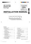
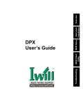
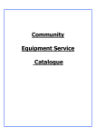
Operator’s Manual
2 Ton Aluminum / Steel
Service Jack
Model 50102
10 am - 7 pm, Central Time,
WARNING: Before using this product,
read this Operator’s Manual and follow
all its Safety Rules and Operating
Instructions.
Safety
Operation
Maintenance
Sears Brands Management Corporation, Hoffman Estates, IL 60179 U.S.A.
www.craftsman.com
Printed in China
AIR PURGE PROCEDURE
IMPORTANT: BEFORE FIRST USE, perform the following Air Purge Procedure to remove any air
that may have been introduced into the hydraulic system as a result of product shipment and
handling.
ASSEMBLE AND INSERT HANDLE
See ASSEMBLY on page 3 to assemble
handle. Loosen handle socket screw.
Insert end of handle into handle socket.
Tighten screw.
TURN HANDLE CLOCKWISE
Turn handle clockwise until it
stops to ensure that release
valve is closed.
RAPIDLY PUMP
Rapidly pump the handle 6 - 8 times.
Leave handle in down position to
expose oil fill plug.
TURN HANDLE
COUNTERCLOCKWISE
Turn handle counterclockwise
2 full turns to fully open
release valve.
6
TURN HANDLE CLOCKWISE
Turn the handle clockwise until it
stops.
7
6
READY TO USE
Jack is now ready for use. Check
for proper pump action.
PURGE AIR
With a flat blade screwdriver,
push the oil fill plug slightly to
the side to purge trapped air
from system.
Screwdriver
Oil Fill Plug
10 am - 7 pm, Central Time,
NOTE: Repeat this Air Purge Procedure whenever
the jack displays reduced lifting performance.
SAFETY INSTRUCTIONS
Read Operating Instructions
Study, understand and follow all instructions in
this manual before operating the jack. Failure
to heed these warnings may result in loss of
load, damage to the jack and/or jack failure
resulting in personal injury or property damage.
Position the Jack
This jack is designed only for lifting part of the
total vehicle. Position the jack to only lift on the
areas of the vehicle specified by the vehicle
manufacturer.
Use Support Stands
After lifting the vehicle always support the load
with appropriately rated vehicle support stands
before working on the vehicle.
Do Not Overload Jack
Do not overload this jack beyond its rated
capacity. Overloading this jack beyond its rated
capacity can cause damage to or failure of the
jack.
Use on Hard Level Surface
This jack is designed only for use on hard level
surfaces capable of sustaining the load. Use on
other than hard level surfaces can result in jack
instability and possible loss of load.
Center Load on Jack Saddle
Center load on jack saddle before lifting
vehicle. Off-center loads and loads lifted when
the jack is not level can cause loss of load or
damage to the jack.
Do Not Use Jack as Dolly
Do not move or dolly the vehicle while it is on
the jack.
KEEP HANDS AND FEET CLEAR OF THE
JACK HINGE MECHANISM AND GROUND
CONTACT AREA WHEN LOWERING THE
LOAD!
DO NOT work on vehicle supported by jack. Immediately
after lifting, support load with appropriately rated vehicle
support stands before working on vehicle.
WARRANTY
CRAFTSMAN ONE YEAR FULL WARRANTY
FOR ONE YEAR from the date of purchase,
this product is warranted against any defects in
material or workmanship. A defective product
be replaced free of charge.
For warranty coverage details to obtain free
replacement, visit the web page: www.craftsman.com/warranty
This ONE YEAR warranty is void if this product
is ever used while providing commercial
services or if rented to another person. For 90
DAY commercial and rental use terms, see the
Craftsman warranty web page.
This warranty gives you specific legal rights,
and you may also have other rights which vary
from state to state.
Sears Brands Management Corporation,
Hoffman Estates, IL 60179
DESCRIPTION
Craftsman model 50102 features a 4,000 lbs.
maximum capacity. Lifting range for this jack is
3.87 inches to 18 inches. Jack features an
overload valve bypass system to prevent jack
damage and user injury.
Specifications
Compact design allows use in confined spaces
Maximum load capacity..........2 tons (4,000 lbs.)
Lift range...................................3.87 to 18inches
Weight ......................................................58 lbs.
WARNING: This product contains chemicals known
to the state of California to cause cancer and birth
defects or other reproductive harm.
• Sufficiently loosen the Handle Socket Screw to
insert the assembled handle (Picture 2).
• Line up the square hole located at the bottom
of the handle over the square bolt inside the
Handle Socket.
• Lower the handle onto the bolt. Secure the handle
in place by tightening the Handle Socket Screw.
Handle
Socket Screw
Pump Plunger
Retaining Clip
FEATURES & OPERATION
Operation
Raising the Jack
• Block the vehicle's wheels for lifting stability.
• Refer to the vehicle manufacturer owner's
manual to locate the approved vehicle lifting
points.
• Position the jack so that the saddle will firmly
ASSEMBLY
contact the vehicle lifting point.
• Close the release valve by turning the handle
Assembly
clockwise until it stops.
Handle Assembly
• Pump jack handle until saddle nears contact
• Refer to picture 1 when performing this step.
with vehicle lifting point. Check to see that the
Take off the screw located on handle piece 1.
saddle is centered and will contact lifting point
Attach handle piece 1 and 2 making sure to
firmly.
align the holes on both pieces. Reinsert the
• Continue to pump jack handle to lift vehicle to
screw and tighten it.
desired height.
• Carefully remove the Retaining Clip (Picture 3)
• After lifting, support the load with appropriately
from the handle socket. CAUTION: The socket
rated vehicle support stands before working on
will tend to spring upward when the clip is removed. vehicle.
To prevent possible injury, place one hand on
Lowering the Jack
• Carefully open the release valve by slowly
top of socket to control its upward motion when
turning the handle counterclockwise.
removing clip with other hand.
How it works
With Release Valve Closed
• An upward stroke of the jack Handle draws oil
from the reservoir tank into the plunger cavity.
Hydraulic pressure holds the valve closed,
which keeps the oil in the plunger cavity.
• A downward stroke of the jack Handle
releases oil into the lift cylinder, which forces
the power unit ram out. This raises the saddle.
• When the ram reaches maximum extension,
oil bypasses the lift cylinder through an
overload valve back into the oil reservoir,
protecting the jack from damage. This bypass
system also goes into effect when the jack is
overloaded (load exceeds 4,000 lbs) to protect
the jack from damage and the user from
possible serious injury.
• Opening the release valve allows oil to flow
back into the reservoir. This releases hydraulic
pressure on the ram, which results in lowering
the saddle.
MAINTENANCE
To Add Oil:
• Position jack on the level ground and lower the
saddle.
• Remove the oil plug.
• Fill the oil case until oil level is just beneath
the lower rim of oil fill hole. Replace oil plug.
• Perform the Air Purge Procedure detailed on
page 1 of this Operator’s Manual.
To Replace Oil:
• Fully open release valve by turning handle
counterclockwise as far as it will go.
• Turn the jack over so that old oil will drain from
the oil fill hole.
• Refill through oil fill hole. Keep dirt and other
material clear when pouring. Fill to just
beneath lower rim of hole. Replace oil plug.
• Perform Air Purge Procedure detailed on page
1 of this Operatior’s Manual.
Lubrication
• Add lubricating oil (WD-40) to all moving parts
when needed.
• For light duty use, lubricate every six months.
• For heavy and constant use, lubrication is
recommended every month.
Rust Prevention:
• Check ram and pump plunger on the Power
Unit Assembly every two months (or sooner,
based on usage) for any signs of rust or
corrosion. Lift the jack as high as it goes and
look under and behind the lifting arm. If signs
of rust are visible clean as needed and wipe
down with an oily cloth or WD-40.
• When storing the jack, always have the saddle
and pump plunger in the down postion.
ALWAYS USE A GOOD GRADE HYDRAULIC
JACK OIL. DO NOT USE HYDRAULIC
BRAKE FLUID, ALCOHOL, GLYCERINE,
DETERGENT, MOTOR OIL OR DIRTY OIL.
USE OF AN UN-RECOMMENDED FLUID CAN
CAUSE DAMAGE TO YOUR JACK.
Air Purge Procedure:
During shipment or after oil refill, air may get
into the hydraulic system causing reduced
lifting performance. Perform Air Purge
Procedure as detailed on page 1 of this
Operator's Manual.
Oil Fill Plug
No.
1
2
3
4
5
6
7
8
Description
Q’TY
1
Saddle
1
Lifting Arm
1
Wall Plate Assembly
2
Front Wheel
Rear Caster Assembly 2
1
Handle Assembly
1
Handle Socket
1
Power Unit Assembly
Release valve is not completely closed.
Turn handle clockwise.
Air is in the hydraulics.
Purge air from system.
Low oil level.
Add oil as required.
Oil reservior is overfilled: Drain
excessive oil.
Lubricate moving parts.
Power unit malfunctioning.
Replace the power unit.
For Help Line, Parts and Service:
Call 10 am - 7 pm, CT, Monday - Friday
1-888-448-6746
For Help Line, Parts and Service:
Call 10 am - 7 pm, CT, Monday - Friday
1-888-448-6746
Para la linea de ayuda, partes y servicio:
Llame de 10am-7pm Lunes-Viernes
1-888-448-6746