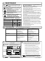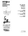
1
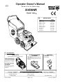
Operator Owner's Manual
1
Thank You for Selecting
SV50HR
Quiet Vac
R
3
SPECIFICATION S
SV50H R
ENGINE: H.P.
5.5 (4.1kW )
ENGINE: TY PE
HO NDA O HV
ENGINE: FU EL CAP .
1.2qt. (1.1L)
ENGINE: O IL CAP.
0.63q t. (0.60L)
W EIG HT: U NIT
151# (68.5kg)
W EIG HT: SH IPP ING
174# (78.9kg)
ENGINE W EIGH T:
36# (16.3kg)
U NIT LENGTH
2
62" (1.57m)
U NIT W IDTH
26.75" (0.68m)
U NIT H EIG HT
42" (1.07m)
ACCESSORIES
HOSE KITS
For vacuuming in hard to reach areas.
Heavy Duty Vacuum
Hose Kit P/N 900998.
4"(102mm) x 7 ' (3.05m)
NOZZLE WEAR GUARD
(STANDARD)
P/N 890413. Extends nozzle life
CASTER KIT
P/N 890447 For use on
hard surface.
when used along curbs and hard
surfaces.
Hose Extension Kit
P/N 890045.
(Kit contains a connector
and a clamp, Hose is not
included)
Felt Filter P/N 890435
For use in all dusty conditions. Can be
used with other liners
BAG LINER OPTIONS
Litter Liner P/N 890006
For use on hard surface where a variety of
debris is present.
Lawn Liner P/N 890009
Used to collect leaves, thatch & grass.
PACKAGED SINGLY
QTY 5 PER PACKAGE
QTY 5 PER PACKAGE
Part No. 890049
Page 1 of 8
Form No. F100202A
5
IN THE INTEREST OF SAFETY
BEFORE STARTING ENGINE, READ AND UNDERSTAND THE “ENTIRE OPERATOR'S MANUAL &
ENGINE MANUAL.”
THIS SYMBOL MEANS WARNING OR CAUTION. DEATH, PERSONAL INJURY AND/OR PROPERTY
DAMAGE MAY OCCUR UNLESS INSTRUCTIONS ARE FOLLOWED CAREFULLY.
WARNING: The Engine Exhaust from this product contains chemicals known
to the State of California to cause cancer, birth defects or other reproductive harm.
WARNING: DO NOT
13. DO NOT tamper with governor springs,
governor links or other parts which may
change the governed engine speed.
1. DO NOT run engine in an enclosed area.
Exhaust gases contain carbon monoxide, an
odorless and deadly poison.
14. DO NOT tamper with the engine speed
selected by the engine manufacturer.
2. DO NOT place hands or feet near moving
or rotating parts.
15. DO NOT check for spark with spark plug
or spark plug wire removed. Use an
approved tester.
3. DO NOT store, spill or use gasoline near
an open flame, or devices such as a stove,
furnace, or water heater which use a pilot
light or devices which can create a spark.
16. DO NOT crank engine with spark plug
removed. If engine is flooded, place throttle
in “FAST” position and crank until engine
starts.
4. DO NOT refuel indoors where area is not
well ventilated. Outdoor refueling is recommended.
17. DO NOT strike flywheel with a hard
object or metal tool as this may cause
flywheel to shatter in operation. Use proper
tools to service engine.
5. DO NOT fill fuel tank while engine is
running. Allow engine to cool for 2 minutes
before refueling. Store fuel in approved
safety containers.
6. DO NOT remove fuel tank cap while
engine is running.
18. DO NOT operate engine without a
muffler. Inspect periodically and replace, if
necessary. If engine is equipped with
muffler deflector, inspect periodically and
replace, if necessary, with correct deflector.
7. DO NOT operate engine when smell of
gasoline is present or other explosive
conditions exist.
19. DO NOT operate engine with an
accumulation of grass, leaves, dirt or other
combustible material in the muffler area.
8. DO NOT operate engine if gasoline is
spilled. Move machine away from the spill
and avoid creating any ignition until the
gasoline has evaporated.
20. DO NOT use this engine on any forest
covered, brush covered, or grass covered
unimproved land unless a spark arrester is
installed on the muffler. The arrester must
be maintained in effective working order by
the operator. In the State of California the
above is required by law (Section 4442 of
the California Public Resources Code).
Other states may have similar laws. Federal
laws apply on federal lands.
9. DO NOT transport unit with fuel in tank.
10. DO NOT smoke when filling fuel tank.
11. DO NOT choke carburetor to stop
engine. Whenever possible, gradually
reduce engine speed before stopping.
12. DO NOT run engine at excessive
speeds. This may result in injury & /or
damage to unit.
SOUND
7
SAFETY INSTRUCTIONS
GENERAL SAFETY
PARTS BAG
CONTROLS & LABELS
ASSEMBLY
OPERATION
PARTS DRAWING & LIST
MAINTENANCE
TROUBLESHOOTING
WARRANTY PROCEDURE
○
○
○
○
○
○
○
○
○
○
○
○
○
○
○
○
○
○
○
○
○
○
○
○
○
○
○
○
○
○
○
○
○
○
○
○
○
○
○
Part No. 890049
○
○
○
○
○
○
○
○
2
3
3
3
4
5
6-7
8
8
8
22. DO NOT run engine without air cleaner
or air cleaner cover.
23. DO NOT operate during excessive
vibration!
24. DO NOT leave machine unattended
while in operation.
25. DO NOT park machine on a steep grade
or slope.
WARNING: DO
1. ALWAYS DO remove the wire from the
spark plug when servicing the engine or
equipment TO PREVENT ACCIDENTAL
STARTING.
2. DO keep cylinder fins and governor
parts free of grass and other debris
which can affect engine speed.
3. DO pull starter cord slowly until resistance is felt. Then pull cord rapidly to avoid
kickback and prevent hand or arm injury.
4. DO examine muffler periodically to be
sure it is functioning effectively. A worn or
leaking muffler should be repaired or
replaced as necessary.
5. DO use fresh gasoline. Stale fuel can
gum carburetor and cause leakage.
6. DO check fuel lines and fittings frequently
for cracks or leaks. Replace if necessary
7. Follow engine manufacturer operating
and maintenance instructions.
8. Inspect machine and work area before
starting unit.
8
VIBRATION
VIBRATION LEVELS 2.5g
Sound tests conducted were in accordance with 2000/14/EEC
and were performed on 2/13/2002 under the conditions listed:
NOTE: Sound power level listed is the highest value for any model in this manual. Please
refer to serial plate on the unit for the sound power level for your model.
6
21. DO NOT touch hot muffler, cylinder, or
fins because contact may cause burns.
Sound level of 97 dBA at operator position
Sunny
GENERAL CONDITION:
TEMPERATURE:
WIND SPEED:
109 dB
48° F (8.9° C)
2 MPH (3.2 kmh)
South East
WIND DIRECTION:
(SV50H MODEL)
29 %
HUMIDITY:
BAROMETRIC PRESSURE:
30.34" Hg (770mm Hg)
Page 2 of 8
Vibration levels at the operators handles were
measured in the vertical, lateral, and longitudinal
directions using calibrated vibration test equipment.
Tests were performed on 04/02/98 under the
conditions listed:
GENERAL CONDITION:
Sunny
TEMPERATURE:
67° F (19.4° C)
WIND SPEED:
5 MPH (8.0 kmh)
WIND DIRECTION:
East
HUMIDITY:
41 %
BAROMETRIC PRESSURE:
29.1" Hg (739mm Hg)
Form No. F100202A
GENERAL SAFETY
9
For your safety and the safety of others, these directions should be followed:
Do not operate this machine without first reading
·DO NOT operate during excessive vibration.
owner's manual and engine manufacturer's manual. ·DO NOT remove bag until engine has been turned off and has
come to a complete stop.
Use of Ear Protection is recommended while
·DO NOT remove hose kit cap on nozzle until engine has been
operating this machine.
turned off and has come to a complete stop.
Use of Eye and Breathing protection is recom·DO NOT operate machine with hose cap, bag or hose removed.
mended when using this machine, especially in dry ·DO NOT use this machine for vacuuming exclusively sand,
and dusty conditions. Debris bag directs dust toward
dust, fine dirt, rock, glass, string like material, grain, rags,
ground, away from the operator and the optional Felt
cans, metal, bark or water.
Filter reduces the amount of dust reintroduced into the ·DO NOT operate this machine on slopes greater than 20%.
environment.
·DO NOT pick up any hot or burning debris, or any toxic or
explosive material.
·DO NOT place hands or feet inside nozzle intake opening, ·DO NOT allow children to operate this equipment.
near debris outlet or near any moving parts.
·DO NOT start engine without debris bag connected firmly in
place to exhaust outlet.
·DO NOT start or operate machine with debris bag zipper
open.
11
These items should be included in your carton. If any
of these parts are missing, contact your dealer.
PACKING CHECKLIST
Check
Check
Check
Literature Assy
890381
Debris Bag
890351
Honda Engine
Manual
LITERATURE ASSY P/N 890048
12
Check
Check
Owner's
Manual
890049
13 CONTROLS
Throttle
Control
14
Literature
Accessories 890380
Check
Litter LIner
Installation
instructions
890007
INSTRUCTION LABELS
These labels should be included on your Vacuum.
If any of these labels are damaged, replace them
before putting this equipment into operation. Item
and part numbers are given to help in ordering
replacement labels..
Check
15
Lawn Liner
Installation
Instructions
890432
Check
Check
Warranty
Card 400972
EU Declaration
of Conformity &
EU Distributor
List 890378
ENGINE LABELS
Honda
STOP
SLOW
400268
WARNING
EXPLOSIVE FUEL
STOP ENGINE AND ALLOW T O
COOL BEFORE REFUELING.
Label Do Not Fill While
Engine Is Hot
Item 63 Part No.400268
DANGER
810736
FAST
Label Danger Keep Hands
and Feet Away
Item 29 Part No.400424
890254
Label Danger Flying Material
Item 62 Part No.810736
Honda - Place
in fast position
to start.
Part No. 890049
Label Ear Eye Breathing
Item No. 86 Part No.
890254
Label Read Owner's
Manual Item 84
Part No.890301
Page 3 of 8
When servicing engine refer to specific manufacturers engine owner's
manual. All engine warranty is covered by the specific engine
manufacturer. If your engine requires warranty or other repair work
contact your local servicing engine dealer. When contacting a dealer
for service it is a good idea to have your engine model number
available for reference(See table above). If you can not locate a
servicing dealer in your area you can contact the manufacturers
national service organization.
To reach:
American Honda: Phone: 770-497-6000
Fax: 770-497-6011
Form No. F100202A
10
ASSEMBLY
Your Billy Goat is shipped from the factory in one carton, completely assembled except for the upper
handle and accessories. Included with machine are caster kit (890447), felt filter bag (1 each), lawn
liner (3 each), and litter liner (3 each).
Read all safety and operating instructions
before assembling or starting this unit.
1.
2.
1. REMOVE items 8 locknut & 74
screws from lower handle (item
27). Attach and securely tighten
upper handle item 6 to lower
handle as shown.
2. REMOVE deflector (item 83)
from box. Discard packing
material. Remove carriage
bolts (item 31) and nut (item 4)
from deflector. Install to bag
plate (item 13) as shown
reusing parts removed (nut
should be on side shown).
Failure to attach
deflector may result in
premature wear to bag.
3.
5.
PUT OIL IN ENGINE
BEFORE STARTING
SEE ENGINE MANUFACTURER'S
MANUAL (some engine manufactures' have different oil checking
procedures)
6.
7.
3. UNFOLD the debris bag
(item 1) position bottom of bag
rod below the bag plate and
pull up and rotate the top of the
bag rod up and secure with the
latch.
6. CONNECT spark plug wire.
7. VERIFY fuel valve on.
4.
4. ATTACH bag hanger strap to bag
supports (item 11), preassembled to
upper handle.
4a. Bag hanger straps are designed
for adjustment when more clearance
is required between bag and ground.
Typically the bottom loop of the strap
is used when operating on turf.
Part No. 890049
Page 4 of 8
Form No. F100202A
Operation
16
INTENDED USE: This machine is designed for vacuuming
leaves, grass clippings and other types of organic litter as
well as debris mixed with cans, bottles and small amounts of
sand; however, vacuuming cans, bottles and sand will affect
the longevity of your machine.
Like all mechanical tools, reasonable care must
be used when operating machine.
Do not operate if excessive vibration occurs. If excessive
vibration occurs, shut engine off immediately and check for
damaged or worn impeller, loose impeller bolt, loose impeller
key, loose engine or lodged foreign objects. Note: See parts list
for proper impeller bolt torque specifications. (See trouble
shooting section on page 7).
Inspect machine work area and machine before operating. Make sure that all operators of this equipment are
trained in general machine use and safety.
PUT OIL IN ENGINE BEFORE STARTING.
16.1
Hint!
ENGINE SPEED: Controlled by throttle lever on the handle.
Under normal conditions, operate at minimum throttle to
accomplish your current cleaning task.
FUEL VALVE: Move fuel valve to "ON" position (Honda only).
CHOKE: Operated with throttle control (Honda).
Post to prime (Briggs & Stratton).
NOTE: Outer bag and rod (items 1 and 3) MUST depress the
bag presence switch (item 17) for the unit to start. See fig.1
IF YOUR UNIT FAILS TO START:
See Troubleshooting on page 8.
16.2
VACUUMING OPERATION
VACUUM NOZZLE HEIGHT ADJUSTMENT: The
vacuum nozzle is raised and lowered by pulling slightly
upward on handle and pulling height adjust T-Handle (item
23) at operators left hand. Lift handle up or down to desired
height, then release T-handle.
FOR MAXIMUM PICKUP: Adjust nozzle height as
close to debris as possible, but without blocking airflow into the
nozzle. NOTE: Never bury nozzle into debris.
CLEARING A CLOGGED NOZZLE
& EXHAUST: Turn engine off and wait for impeller
to stop completely and disconnect spark plug wire.
Wearing durable gloves, remove clog. Danger, the
clog may contain sharp materials. Reconnect spark
plug wire.
16.10
DEBRIS BAG
Debris bags are normal replaceable wear items.
Note: Frequently empty debris to prevent bag overloading with
more weight than you can lift.
Bag liners are included and available for use in various conditions
where debris will be vacuumed. (see Bag Liner Options shown on page 1).
DO NOT place bag on or near hot surface, such as engine.
Be sure engine has come to a complete stop
before removing or emptying bag!!
This vacuum is designed for picking up trash, organic
material and other similar debris (see Safety Warnings page 2-3).
Many vacuums are used where dust is mixed with trash. Your
unit can intermittently vacuum in dusty areas. However, following
these rules will help maintain your machine's ability to vacuum in
dusty conditions:
•Run machine at idle to quarter throttle.
•Machine or pressure-wash debris bag if normal cleaning does
not fully clean bag. Bag should be thoroughly dry before use.
STARTING
ENGINE: See engine manufacturer’s instructions
for type and amount of oil and gasoline used.
Engine must be level when checking and filling oil and
gasoline.
16.3
Having one or more spare Felt Filter (890435) is a good way to reduce
down time while dirty bags are being cleaned.
Do not store with debris in bag. Organic
debris generates heat during decomposition and could damage the bag or start a fire.
16.4
HANDLING & TRANSPORTING:
Using two people to lift machine is recommended. Lift holding the
handle and front of nozzle. Secure in place during transport.
16.5
STORAGE
Never store engine indoors or in enclosed poorly ventilated
areas with fuel in tank, where fuel fumes may reach an open
flame, spark or pilot light, as on a furnace, water heater, clothes
dryer or other gas appliance.
If engine is to be unused for 30 days or more, prepare as
follows:
Be sure engine is cool. Do not smoke. Remove all
gasoline from carburetor and fuel tank to prevent gum deposits
from forming on these parts and causing possible malfunction of
engine. Drain fuel outdoors, into an approved container, away
from open flame. Run engine until fuel tank is empty and
engine runs out of gasoline.
NOTE: Fuel stabilizer (such as Sta-Bil) is an acceptable
alternative in minimizing the formation of fuel gum deposits
during storage. Add stabilizer to gasoline in fuel tank or storage
container. Always follow mix ratio found on stabilizer container.
Run engine at least 10 min. after adding stabilizer to allow it to
reach the carburetor.
COMPOST
Vacuumed leaves, grass and other organic material from your
own yard can be emptied into a pile or composter to provide
enriched soil for later use as fertilizer in gardens and flower beds
Note: Allow green chips to dry before spreading around living
plants.
Part No. 890049
Page 5 of 8
THROTTLE
STOP
SPARK
PLUG
BAG PRESENCE
SWITCH
fig 1.
Form No. F100202A
18
PARTS DRAWING
SV50HR
Part No. 890049
Page 6 of 8
Form No. F100202A
19
* Denotes standard hardware item that may be purchased locally.
Ite m
No.
1
2
3
4
5
6
7
8
9
10
11
12
13
14
15
16
17
18
19
20
21
22
23
24
25
26
27
28
29
30
31
32
33
34
35
36
37
38
39
40
41
42
43
44
45
46
47
48
49
50
51
52
53
54
55
56
57
58
59
60
Part No. 890049
PARTS
LIST
OUTER DEBRIS BA G
THROTTLE CONTROL
ROD BA G NO CHA NNEL
NUT LOCK (1/4 - 20 )
SCREW CA P ( 1/4 - 20 x 1-1/2 HEX )
HA NDLE UPPER W/GRIP
A XLE HEIGHT A DJUST
SCREW CA P 5/16 - 18 x 1-3/4
CLA MP CA BLE 1" I.D.
TY WRA P
BA G BA G SUPPORT
LA TCH BA G
PLA TE BA G NO CHA NNEL
BRA CKET HA NDLE SV
BOLT CA RR. 5/16 - 18 x 3/4 ZP
WA SHER FLA T 1/2 SA E
SWITCH PLUNGER
BRA CKET - LOWER HEIGHT A DJUSTMENT
SCREW 3/8 X 1 1/2 TA PTITE
SPRING-COMPRESSION
TIRE - ONLY (PER A SSY )
PIN - HA IR COTTER
CA BLE HEIGHT A DJUSTMENT
BOLT - CA RRIA GE 5/16 - 18 x 4 1/2
GRIP HA NDLE
NUT LOCK 5/16 - 18 HEX
HA NDLE LOWER
PLA TE HA NDLE SUPPORT
ENGINE PLA TE MOUNT
WA SHER FLA T CUT 5/16
SCREW CA RRA IGE 1/4-20 x 3/4
SCREW CA P 1/4 - 20 x 1/2 HWH
STRA IN RELIEF HA Y CO 1244
WHEEL A SS’Y (incl. items 21)
WA SHER 0.75 “C”
PLA TE DEFLECTOR SV
HEIGHT A DJUST A SSY (incl. items 18,20,22,23,25)
SEA L BA G
1/2-13 CA P NUT NP W/PA TCH
SCREW CA P 1/4 - 20 x 1 - 1/4
HA RNESS A SSY
SCREW SELF TA PPING 10 - 24 x 1/2
NOZZLE MA INFRA ME A SS’Y (incl. one of items 29,44,42)
PLUG HOUSING
SCREW CA P 1/4-20x 1-3/4
SCREW SM 1/4 x 3/4 TY PE A
PLA TE SKID (incl. items 78)
IMPELLER A SS’Y (incl. items 49, 50, 51)
KEY
WA SHER LOCK 3/8 TWISTED TOOTH
SCREW CA P 3/8 -24 x 1 (HA RDENED)(TORQ.50 FT-LBS)(68N.m)
HOUSING A SS’Y (incl. items 29, 62, 84, 86)
ENGINE HONDA 5.5 H.P. GXV 160 KN12
TERMINA L PIGGY BA CK 3/16
LA BEL DO NOT FILL WHEN ENGINE IS HOT
LA BEL EA R EY E BREA THING
LA BEL DA NGER FLY ING DEBRIS
LA BEL REA D OWNER'S MA NUA L
LA BEL DA NGER CUT FINGER
PLA TE UPPER HEIGHT A DJUST
Page 7 of 8
SV 50HR
Part No.
890351
850270
890036
*8160001
*8041008
890439
890389
*8041031
900813
*900407
900039
890356
890039
890532
8024039
*8172011
890440
890021
890408
900136
900507
900471
890019
*8024054
400570
*8160002
890346
900933
890337
*8171003
*8024021
890359
500282
900509
900997
890011
890013
890018
890530
*8041007
890442
*8123086
890391
900146
*8041009
*8122082
890413
890382
900162
400502
900154
890388
900615
890010
400268
890254
810736
890301
400424
890005
QTY
1
1
1
17
2
1
1
2
2
2
1
1
1
2
2
4
1
1
4
1
1
1
1
4
2
6
1
1
1
2
12
6
1
4
1-0
1
1
2
4
4
1
1
1
1
2
4
1
1
2
1
1
1
1
1
1
1
1
1
2
1
Form No. F100202A
MAINTENANCE
17
Use only a qualified mechanic for any
adjustments, disassembly or any kind
of repair .
DISCONNECT SPARK PLUG WIRE
BEFORE SERVICING UNIT.
ENGINE: See engine manufacturer
operator's instructions.
RECONNECT SPARK PLUG WIRE,
GUARDS, BAG, CAPS AND / OR
HOSE BEFORE STARTING ENGINE.
Follow these hourly
maintenance intervals.
Maintenance Schedule
Maintenance Operation
Every
Use
Every 5 hrs
or (Daily)
Engine (See Engine Manual)
Check for excessive vibration
Clean Debris Bag
Inspect for loose parts
Inspect for worn or damaged parts
20
TROUBLESHOOTING
Before Requesting Service Review These Suggestions
Problem
Possible Cause
Solution
Will not vacuum or has poor vacuum performance. · Dirty or full debris bag or filter.
· Nozzle height set too high or too low .
· Hose kit cap missing.
· Clogged nozzle or exhaust.
· Excessive quantity of debris.
· Clean debris bag and filter. Shake bag clean or
w ash.
· Adjust nozzle height.
· Check for hose kit cap.
· Unclog nozzle or exhaust (see page 5)
· Allow air to f eed w ith debris.
Abnormal vibration.
· Loose or out of balance impeller.
· Loose engine.
· Check impeller and replace if required.
· Check Engine.
Engine w ill not start.
· Throttle in off position.
· Engine not in full choke position.
· Out of gasoline or bad or old gasoline.
· Spark Plug w ire disconnected.
· Gas Valve of f.
· Dirty air cleaner.
· Check throttle
· Check throttle, choke position
· Check throttle, choke position and gasoline.
· Connect spark plug w ire.
· Turn on gas valve.
· Clean or replace air cleaner. Contact a qualified
service person.
· Bag not fully engaged or Rod in bag is bent.
· Saf ety Interlock disengaged on bag plate.
22.1
21
For damaged or imbalanced
impeller
1. Wait for engine to cool and disconnect spark plug.
2. Drain fuel and oil from the engine.
3. Remove engine, impeller and mounting plate by removing nuts
(item 26) around outside of housing.
4. Leaving engine fastened to plate, remove impeller bolt (item 50)
and lock washer and slide impeller off crankshaft ( A puller may be
required). CAUTION: Do not drop impeller.
5. If impeller does not slide off crankshaft, place two crowbars
between impeller and housing on opposite sides. Pry impeller away
from engine until it loosens. Using a penetrating oil can help loosen
a stuck impeller.
6. If the impeller cannot be loosened, obtain a 1” (25.4mm) longer
bolt of the same diameter and thread type as the impeller bolt.
Invert engine and impeller and support engine above ground to
prevent recoil damage. Thread longer bolt by hand into the
crankshaft until bolt bottoms. Using a suitable gear or wheel puller
against the bolt head and the impeller back-plate (near the blades),
remove impeller from shaft.
7. To reinstall impeller, use a new impeller bolt and lockwasher
8. Tighten impeller bolt. Torque impeller bolt to 50 Ft. Lbs. (68 N.m).
9. Reinstall engine, impeller, and mounting plate onto housing in
reverse order of removal.
10. Before connecting spark plug wire, slowly pull engine starting
rope to insure that impeller rotates freely.
11. Reinstall spark plug wire.
WARNING: TO AVOID PERSONAL INJURY, ALWAYS TURN
MACHINE OFF, MAKE SURE ALL MOVING PARTS COME
TO A COMPLETE STOP.
17.2
IMPELLER REMOVAL
17.1
WARRANTY PROCEDURE
Engine Service and Warranty
22
Contact your nearest engine manufacturer's authorized
servicing dealer.
Record your machine model, serial number and
Serial Plate
date-of-purchase and where purchased
The Machine should be taken to the dealer from whom it was
purchased or to an authorized Billy Goat dealer.
1803 S.W. Jefferson
Lee's Summit,
MO 64062 / USA
Tel (816) 524-9666
Fax (816) 524-6983
R
Model
The owner should present the remaining half of the Warranty
Registration Card, or, if this is not available, the invoice or receipt.
The Warranty Claim will be filled in by the authorized Billy Goat Dealer,
who will send it with the faulty part to Billy Goat headquarters.
Serial No.
The Quality / Service department at Billy Goat headquarters will study
the claim and parts and will notify their conclusions.
109 dB
Unit(Weight)
lbs.
The decision by the Quality / Service department at Billy Goat
headquarters to approve or reject a Warranty claim is final and
binding.
Engine Power
kg
kW
rpm
min-1
Purchase
Date
Part No. 890049
Please fill in the WARRANTY CARD and send the upper part to Billy Goat.
The WARRANTY terms are stated on the lower part which remains with the
user. Whenever a Billy Goat Machine is faulty due to a defect in material
and / or workmanship, the owner should make a warranty claim as follows:
Note: To process a Warranty Claim, it is necessary to quote the Model
& Serial number who are printed on the Billy Goat Serial Plate.
BILLY GOAT INDUSTRIES INC.
1803 S.W. JEFFERSON LEE'S SUMMIT, MO 64082 / USA
PHONE: 816-524-9666 FAX: 816-524-6983
www.billygoat.com
Purchased
from
Page 8 of 8
Form No. F100202A
Gardening Supply
Patio Barbecues
Outdoor Barbecues
Landmann Barbecues
Gas Barbecues UK
Charcoal Barbecues
Brush Cutters
Gas Barbecues
Brushcutters
Cheap Gas Barbecues
Blower Vacs
Masonry Barbecues
Chain Saws
Chainsaws
Cultivators
Cylinder Lawn Mowers
Echo Chainsaws
Echo Strimmers
Electric Chainsaws
Fertiliser Spreaders
Garden Blowers
Garden Rollers
Lawn Rollers
Garden Shredders
Garden Tractors
Garden Vacuums
Hayter Lawn Mowers
Hedge Cutters
Hover Mowers
Husqvarna chainsaws
Kawasaki Brush Cutters
Hedgecutters
Kawasaki
Strimmers
Lawn Mowers
Scarifiers
Lawn Tractors
Leaf Vacuums
Ride on mowers
Electric Garden
Shredders
Petrol Chainsaws
Rotary Mowers
Petrol Garden
shredders
Leaf Blowers
Ride on lawn
Petrol Hedge Cutters
mowers
Rotavators
Ryobi Strimmers
Cheap Garden
ALKO Garden Shredders Shredders
Garden Patio Heaters
Outdoor Patio Heaters
Gas Patio Heaters
Patio Heater Covers
Garden Heaters
Greenhouse Heaters
Patio Heaters
Green house
heaters
Gas Greenhouse
heaters
Stainless Steel Patio
Heaters
Table Top Patio Heaters
Patio Heaters UK
Grit Spreaders
Patio Heaters with
Covers
Gardena Hedgecutters
Christmas Gardening
Gifts
Kawasaki brushcutters
Petrol Strimmers
Midgeater Plus
Barbecues
Cylinder Mowers