1
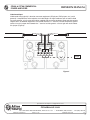
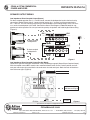
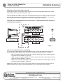
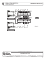
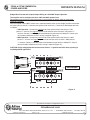
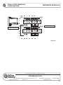
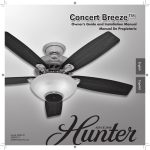
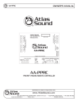
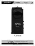
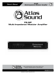
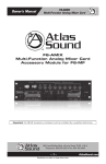
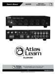
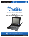
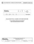
CP400 & CP700 COMMERCIAL POWER AMPLIFIER PROTECT OWNER'S MANUAL PROTECT LIMIT LIMIT SIGNAL CP700 SIGNAL CH-1 CH-2 POWER Commercial Power Amplifier CP400 & CP700 Commercial Power Amplifier HIGH-PERFORMANCE, DUAL-CHANNEL, COMMERCIAL AUDIO AMPLIFIERS IN DIR. OUTPUT + - AUDIO TRANSFORMER 0 70 100 I S O L . IN CH-1 AMPLIFIER INPUTS OUTPUT CH-2 - 0 70 100 I S O L . 40 32 2 6 1 8 16 14 0 - 100V + GND POWER 22 56 + 22 LEVEL THRU 1 8 16 14 10 8 6 4 2 0 25V 12 + - 10 8 6 4 2 0 70V + OUTPUT 12 BRIDGE MONO - - CH-2 THRU - GND 6 + 25V - 100V + AUDIO TRANSFORMER CH-1 - 40 32 2 8, 4, and 2 Ohms DIR. OUTPUT AC100V-50/60Hz AC120V-50/60Hz AC230V-50/60Hz AC240V-50/60Hz 70V + + 56 CH-2 BRIDGE MONO + - 0 - + -0 Per Channel Output Power 400 W / 4 Ohms 350 W / 70.7 V 8, 4, and 2 Ohms -0 CP700 Commercial Power Amplifier CH-1 LEVEL MADE IN CHINA CAUTION TO REDUCE THE RISK OF ELECTRIC SHOCK DO NOT REMOVE COVER (OR BACK) NO USER SERVICEABLE PARTS INSIDE REFER SERVICING TO QUALIFIED SERVICE PERSONNEL STEREO CAUTION PARALLEL RISK OF ELECTRIC SHOCK DO NOT OPEN AVIS RISQUE DE CHOC ELECTRIQUE NE PAS OUVRIR Specifications are subject to change without notice AtlasSound.com 1601 JACK MCKAY BOULEVARD ENNIS, TEXAS 75119 U.S.A. • ©2008 ATLAS SOUND LP BRIDGE 1601 Jack McKay Blvd., Ennis, TX 75119 (800) 876-3333 AtlasSound.com Printed in U.S.A. TELEPHONE: (800) 876-3333 • FAX: (800) 765-3435 ATS002102 RevD 2/08 PP CP400 & CP700 COMMERCIAL POWER AMPLIFIER OWNER'S MANUAL TABLE OF CONTENTS Introduction, Features, Applications.............................................................………………………………….3 Front Panel Description......................................................................…………………………………..…….4 Rear Panel Description......................................................................…………………………………..……..5 Input Wiring......................................................................…………………………………..…………………..7 Speaker Output Wiring...................................................................................………………………………..9 Specifications..........................................................................................…………………………………….15 Warranty................................................................................................……………………………………...16 Safety Instructions Please Read Carefully Before Installing or Operating This Product • Read instructions fully. • Pay attention to any and all warnings. • Connect this amplifier only to the correct operating voltage. • Do not attempt to service this unit. Only a qualified service technician should open this unit for servicing. • Warning – To reduce the risk of fire or electric shock, do not expose this appliance to rain or moisture. Hearing Damage! All professional loudspeaker systems are easily capable of producing very high sound pressure levels. Use care with the operation of this amplifier and wear the appropriate hearing protection. Exposure to excessive sound pressure levels can cause permanent hearing damage. Shock Hazard! The Atlas Sound CP400 and CP700, when in operation, can produce a shock hazard at the speaker terminals. Make sure the amplifier is turned off when installing or removing connections at the speaker terminal barrier strip. After connecting the proper speaker load, REPLACE the terminal strip cover! Ventilation Although the CP400 and CP700 are internally fan cooled and have thermal protection circuitry, adequate ventilation is required to ensure trouble-free operation. When rack mounting one or more of the Atlas Sound CP Series power amplifiers, install an exhaust fan in the rack to evacuate heat buildup. Consult Atlas Sound’s Technical Support at 1-800-876-3333 for advice on thermal management and assistance with rack selection for this product. Rack Mounting Although the internal output transformers are mounted close to the front panel, when rack mounting the CP400 and CP700, be sure the unit has adequate front and rear support. Specifications are subject to change without notice AtlasSound.com 1601 JACK MCKAY BOULEVARD ENNIS, TEXAS 75119 U.S.A. • ©2008 ATLAS SOUND LP Printed in U.S.A. TELEPHONE: (800) 876-3333 • FAX: (800) 765-3435 ATS002102 RevD 2/08 PP 2 CP400 & CP700 COMMERCIAL POWER AMPLIFIER OWNER'S MANUAL INTRODUCTION Congratulations and thank you for purchasing the Atlas Sound CP400/CP700 dual channel power amplifier. This product is a professional grade audio power amplifier specifically designed for demanding contractor applications and engineered to provide years of faithful service. Two independent channels driven by separate power supplies ensure maximum channel separation and ultra low distortion figures. Whether your application is a large distributed constant voltage sound system or a high SPL sound reinforcement system, the Atlas Sound Series is the answer for high power/low cost amplification needs. Features • Independent power supplies • Soft clip limiter protection • Dual-speed, high efficiency fan cooling • Stepped attenuators mounted on the rear for security • Stereo, bridge, or parallel operating modes selectable via rear mounted switch • Balanced inputs on barrier strip and XLR connectors • Loop through feature on male XLRs, one per channel input • Short-circuit, temperature, and DC offset protection • 25V, 70.7V, 100V, and direct coupled (2,4, and 8 Ω) outputs mounted on barrier strips with covers for safety • Toroidal output transformers provide extended high frequency response and effectively lower the electrical interference • Power-up muting Applications The Atlas CP400/CP700 are the perfect choice for distributed paging/BGM systems, foreground music systems, and distributed sound masking applications. They are also at home in night clubs, theaters, portable sound systems, and anywhere clean high-fidelity audio amplification is needed. Specifications are subject to change without notice AtlasSound.com 1601 JACK MCKAY BOULEVARD ENNIS, TEXAS 75119 U.S.A. • ©2008 ATLAS SOUND LP Printed in U.S.A. TELEPHONE: (800) 876-3333 • FAX: (800) 765-3435 ATS002102 RevD 2/08 PP 3 CP400 & CP700 COMMERCIAL POWER AMPLIFIER OWNER'S MANUAL Front Panel Description 2 PROTECT PROTECT LIMIT LIMIT SIGNAL CP700 SIGNAL CH-1 CH-2 1 POWER Commercial Power Amplifier 3 4 Figure 1 1. Power Switch This rocker switch supplies power to the amplifier. A red LED located above the power CH-1 CH-1 AMPLIFIER INPUTS switch will illuminate when the amplifier is switched on. IN 8, 4, and 2 Ohms CP700 Commercial Power Amplifier Per Channel Output Power 400 W / 4 Ohms 350 W / 70.7 V DIR. OUTPUT + - IN AUDIO TRANSFORMER 0 70 100 I S O L . OUTPUT CH-2 - + BRIDGE MONO 70V + - 25V + + CH-1 - GND - + 2. Protect LED Indicators The amplifier features several types of protection circuitry to prevent damage during power-up or fault conditions. If any of these LEDs illuminate, one of the various protection features is safeguarding the amplifier. The output relays will disconnect the speaker loads when the protection circuitry detects a fault condition. • Loudspeaker Protection - When power is first applied, the speaker protection relay is open, preventing transients from reaching the loudspeakers. After the internal power supplies have stabilized, the relay will close, connecting the amplifier output to the load. The yellow Protect LEDs will illuminate during this power-up process. • Thermal Protection - The amplifier protection circuitry monitors itself for excessive internal operating temperatures. In the event this circuitry detects abnormal thermal conditions (blocked cooling fan or high ambient temperatures), the speaker relay will disconnect the speaker load from the amplifier. Once the internal operating temperature drops back to a safe level, the relay will close, reconnecting the speaker load to the amplifier. • Short Circuit Protection - The yellow Protect LEDs will illuminate should the amplifier detect a short circuit on the attached speaker load or if the load impedance is too low. When this condition is detected, the internal speaker relays will open up, disconnecting the load from the amplifier. The protection circuitry will stay activated until the fault is cleared. 100 I S O L . CH-2 OUTPUT + GND CAUTION TO REDUCE THE RISK OF ELECTRIC SHOCK DO NOT REMOVE COVER (OR BACK) NO USER SERVICEABLE PARTS INSIDE REFER SERVICING TO QUALIFIED SERVICE PERSONNEL 1 8 16 14 0 - 100V + POWER 22 40 32 2 25V 56 + - 22 LEVEL THRU 1 8 16 14 10 8 6 4 2 0 70V 10 8 6 4 2 0 - 12 6 THRU - BRIDGE MONO 6 70 40 32 2 0 56 - 100V + AUDIO TRANSFORMER 12 AC100V-50/60Hz AC120V-50/60Hz AC230V-50/60Hz AC240V-50/60Hz - 0 + -0 8, 4, and 2 Ohms DIR. OUTPUT -0 CH-2 LEVEL MADE IN CHINA STEREO CAUTION PARALLEL RISK OF ELECTRIC SHOCK DO NOT OPEN AVIS RISQUE DE CHOC ELECTRIQUE NE PAS OUVRIR BRIDGE 1601 Jack McKay Blvd., Ennis, TX 75119 (800) 876-3333 AtlasSound.com Note: Once the specific fault has been corrected, the power may have to be cycled to reset the protection circuitry. 3. Signal “Status” LED Indicator The green “Status” LEDs will illuminate once the input signal has reached -26 dBV or higher. Specifications are subject to change without notice AtlasSound.com 1601 JACK MCKAY BOULEVARD ENNIS, TEXAS 75119 U.S.A. • ©2008 ATLAS SOUND LP Printed in U.S.A. TELEPHONE: (800) 876-3333 • FAX: (800) 765-3435 ATS002102 RevD 2/08 PP 4 CP400 & CP700 COMMERCIAL POWER AMPLIFIER OWNER'S MANUAL 4. Limit LED Indicator The CP400 and CP700 come equipped with limiter circuitry and LEDs to indicate when this circuitry is activated. The limiter circuitry engages only when the input signals reach a specific, factory set CP700 magnitude. Once this limit has been reached, the circuitry will reduce the input level enough to prevent clipping at the speaker output terminals. PROTECT PROTECT LIMIT LIMIT SIGNAL SIGNAL CH-1 CH-2 POWER Commercial Power Amplifier rear Panel Description 6 IN 8, 4, and 2 Ohms DIR. OUTPUT + - AUDIO TRANSFORMER 0 70 100 I S O L . IN CH-1 CH-2 + - + + - 100V + AUDIO TRANSFORMER 0 70 100 I S O L . OUTPUT 6 40 32 2 GND CAUTION TO REDUCE THE RISK OF ELECTRIC SHOCK DO NOT REMOVE COVER (OR BACK) NO USER SERVICEABLE PARTS INSIDE REFER SERVICING TO QUALIFIED SERVICE PERSONNEL 1 8 16 14 0 - 100V + POWER 22 56 + 22 LEVEL THRU 1 8 16 14 10 8 6 4 2 0 25V 12 + - + 10 8 6 4 2 0 70V - 12 - GND CH-2 THRU - BRIDGE MONO CH-1 - 6 DIR. OUTPUT AC100V-50/60Hz AC120V-50/60Hz AC230V-50/60Hz AC240V-50/60Hz 25V 40 32 2 8, 4, and 2 Ohms + - 56 CH-2 70V 0 - + BRIDGE MONO 8 AMPLIFIER INPUTS OUTPUT -0 Per Channel Output Power 400 W / 4 Ohms 350 W / 70.7 V CH-1 -0 10 CP700 Commercial Power Amplifier 7 LEVEL MADE IN CHINA STEREO CAUTION PARALLEL RISK OF ELECTRIC SHOCK DO NOT OPEN AVIS RISQUE DE CHOC ELECTRIQUE NE PAS OUVRIR BRIDGE 1601 Jack McKay Blvd., Ennis, TX 75119 (800) 876-3333 AtlasSound.com 5 11 9 Figure 2 5. Gain Controls One stepped attenuator per channel increases or decreases the sensitivity by 2 dB per step. Maximum voltage gain is 32 dB. 6. CH1/CH2 Inputs (XLR Connectors) Two female XLR inputs (one per channel) are provided. These inputs are balanced and configured as follows: pin 1 ground, pin 2 +, pin 3 -. The XLR connections are typically used in portable audio systems where quick connect and disconnect is warranted. 7. Balanced Barrier Strip Inputs Balanced inputs are provided on this barrier strip for permanent installation applications. The use of the appropriate spade type lug is highly recommended for best connection integrity and a neat, professional appearance. 8. CH1/CH2 Loop Through Two male XLR (one per channel) are provided for looping the input signals to other devices. These connectors are wired in parallel with the female XLR inputs, pin for pin. Specifications are subject to change without notice AtlasSound.com 1601 JACK MCKAY BOULEVARD ENNIS, TEXAS 75119 U.S.A. • ©2008 ATLAS SOUND LP Printed in U.S.A. TELEPHONE: (800) 876-3333 • FAX: (800) 765-3435 ATS002102 RevD 2/08 PP 5 CP400 & CP700 COMMERCIAL POWER AMPLIFIER OWNER'S MANUAL 9. Stereo/Parallel/Bridge Switch This 3 position switch changes the operating mode of the amplifier. DO NOT move this switch when the amplifier is powered up and connected to a load. • Stereo - When the switch is set to this position, the amplifier operates as two independent amplifiers. Use this position for stereo program material or for two discreet paging/sound masking zones. • Parallel - When the switch is set to this position a single mono input signal is to be used. Connect the input wiring to either channel 1 OR channel 2. The one input signal will drive both amp channels. Use this position when two speaker zones are being fed by a mono signal. (See note below) • Bridge - When the switch is set to this position, connect the mono input signal to channel 1 ONLY. The speaker load is connected across the two positive terminals as shown in Figure 7 on page 10. The amplifier will deliver approximately twice the voltage across the load. Please observe the minimum load specification when operating in Bridge mode. Note: A 6 dB loss of output power will occur when operating in parallel mode. To over come this loss, connect the positive terminal on input 1 to the positive terminal on input 2 and connect the negative terminal on input 1 to the negative terminal on input 2. Short lengths of 22-gauge wire can be used. 10. CH1/CH2, Low Impedance Speaker Outputs The amplifier direct speaker outputs bypass the internal constant voltage transformers and are used for direct connection to loudspeakers. The amplifier will operate into 2, 4, and 8 Ω loads. The use of appropriately sized spade lugs is recommended for speaker wire termination; connect the speaker line common to the “-” terminal and the positive lead to the “+” terminal. For high power applications, use the proper gauge wire for the speaker connections. Contact Atlas Sound Tech Support (1-800-876-3333) for assistance in determining the proper size wire. 11. CH1/CH2, 25/70.7/100V Speaker Outputs The amplifier will drive constant voltage speaker loads for use in commercial business music/paging systems and sound masking systems. The use of spade lugs for terminating and connecting the speaker home runs is recommended. The speaker line common connects to the “0” terminal and the positive lead connects to the desired voltage for required system requires for proper operation (Figures 8,9,10; Pages 11-12). Calculating Constant Voltage Loads To calculate the maximum quantity of transformer coupled loudspeakers you can safely connect to the amplifier, first add up the total number of speakers that will be connected to one channel of the amplifier, then multiply that total speaker number by the tap setting you plan to use. The result will be the load in watts that the amp output channel will see. It is good engineering practice to leave a 20% margin below the maximum rated output power of the amplifier. In this case, one channel of the amplifier can supply 350 W of power at 70.7V. Derate this by 20%, leaving 280 W of power available for constant voltage speakers. Specifications are subject to change without notice AtlasSound.com 1601 JACK MCKAY BOULEVARD ENNIS, TEXAS 75119 U.S.A. • ©2008 ATLAS SOUND LP Printed in U.S.A. TELEPHONE: (800) 876-3333 • FAX: (800) 765-3435 ATS002102 RevD 2/08 PP 6 CP400 & CP700 COMMERCIAL POWER AMPLIFIER OWNER'S MANUAL Input Wiring Balanced Inputs Balanced input wiring requires two conductors with shield (22-gauge is the most common). The use of crimp type spade lugs is highly recommended for permanent installations. At the input section located on the rear of the amplifier, wire the “hot”/positive lead to the “+” terminal, the “common”/negative lead to the “-” terminal and the shield/drain to the “ground” terminal (Figure 3). The XLR inputs (+4 dB balanced line level) can be utilized with standard 3-pin XLR male to female patch cables to accommodate outputs from a mixer, equalizer, or crossover when the amplifier is used as a portable sound system amplifier. White (+) Black (-) Shield White (+) Black (-) Shield Specifications are subject to change without notice AtlasSound.com 1601 JACK MCKAY BOULEVARD ENNIS, TEXAS 75119 U.S.A. • ©2008 ATLAS SOUND LP Printed in U.S.A. Figure 3 TELEPHONE: (800) 876-3333 • FAX: (800) 765-3435 ATS002102 RevD 2/08 PP 7 CP400 & CP700 COMMERCIAL POWER AMPLIFIER OWNER'S MANUAL Unbalanced Input Unbalanced wiring typically is found on consumer equipment (CD players, DVD players, etc.) and is generally a compromise of noise rejection and cable lengths. A single conductor and an overall shield are most common, as in the standard cables supplied with consumer equipment. Keep unbalanced wire lengths within 10' between equipment, wire the hot lead to the “+” terminal, and the shield to the ground terminal. Install a jumper wire between the “-” terminal and the ground – a loss of gain will result without this jumper (Figure 4). White/Red (+) Shield White/Red (+) Shield Jumper Figure 4 Specifications are subject to change without notice AtlasSound.com 1601 JACK MCKAY BOULEVARD ENNIS, TEXAS 75119 U.S.A. • ©2008 ATLAS SOUND LP Printed in U.S.A. TELEPHONE: (800) 876-3333 • FAX: (800) 765-3435 ATS002102 RevD 2/08 PP 8 CP400 & CP700 COMMERCIAL POWER AMPLIFIER OWNER'S MANUAL Speaker Output Wiring Low Impedance Direct Coupled Output (Stereo) For direct coupled operation into 2, 4, and 8 Ω loads, connect the loudspeaker leads to the barrier strip connections labeled “Direct Output”; connect the hot lead to the “+” terminal and the common lead to the “-” terminal. The use of heavy gauge wiring is recommended to avoid voltage drops, which can occur as a result of wasted power in the cable. Contact Atlas Sound Tech Support (1-800-876-3333) for suggestions on cable capacities. Be sure you know the quantity of speakers and cable lengths before calling (Figure 5). CH-1 CP700 Commercial Power Amplifier 8, 4, and 2 Ohms DIR. OUTPUT To direct coupled Per Channel Output Power loudspeakers 400 W / 4 Ohms 350 W / 70.7 V + - BRIDGE MONO 8, 4, and 2 Ohms DIR. OUTPUT 0 - + CH-2 AUDIO TRANSFORMER + - 70 70V + - 100 I S O L . 25V 70 OUTPUT + - 100V + AUDIO TRANSFORMER 0 CH-1 100 I S O L . CH-2 OUTPUT To direct coupled AC100V-50/60Hz AC120V-50/60Hz loudspeakers AC230V-50/60Hz Switch set to “Stereo” AC240V-50/60Hz - - BRIDGE MONO 70V + - 25V + - 100V + POWER MADE IN CHINA Figure 5 CAUTION Low Impedance Direct Coupled Output (Parallel Mono) RISK OF ELECTRIC SHOCK CAUTION NOT OPEN Observe the speaker connection information inTHE the preceeding paragraph (StereoDO Direct Coupled Output). TO REDUCE RISK OF ELECTRIC SHOCK AVIS RISQUE DE CHOC ELECTRIQUE DO NOT REMOVE COVER (OR BACK) With the amplifier turned OFF, move the rear mounted selector switch to the “Parallel” position and conNE PAS OUVRIR NO USER SERVICEABLE PARTS INSIDE REFER SERVICINGone TO QUALIFIED SERVICE PERSONNEL nect your mono input wiring to either the channel or channel two inputs. Both channels will be driven from this mono signal (Figure 6). White Black Shield Optional Jumpers See Note on Page 6 Switch set to “Parallel” Specifications are subject to change without notice AtlasSound.com 1601 JACK MCKAY BOULEVARD ENNIS, TEXAS 75119 U.S.A. • ©2008 ATLAS SOUND LP Printed in U.S.A. Figure 6 TELEPHONE: (800) 876-3333 • FAX: (800) 765-3435 ATS002102 RevD 2/08 PP 9 CP400 & CP700 COMMERCIAL POWER AMPLIFIER OWNER'S MANUAL Bridge Mono Configuration (Direct Coupled) If higher power levels are required, the Atlas amplifier can be used in Bridge Mono mode, which utilizes both channels of the amp across the speaker load. With the amplifier turned OFF, move the rear mounted selector switch to the “Bridge” position and connect the input signal to channel one. Connect your speaker load (4 and 8 Ω only) across the “+” terminals of both channels, with channel 1 being positive and channel 2 being negative (Figure 7). Caution: A high voltage potential exists across the two “+” speaker terminals when operating in any Bridge Mode application! CP700 Commercial Power Amplifier Per Channel Output Power 400 W / 4 Ohms 350 W / 70.7 V CH-1 8, 4, and 2 Ohms DIR. OUTPUT - CH-2 8, 4, and 2 Ohms + - AC100V-50/60Hz AC120V-50/60Hz AC230V-50/60Hz AC240V-50/60Hz - AUDIO TRANSFORMER 0 - + BRIDGE MONO DIR. OUTPUT To loudspeakers, 4 Ω minimum + 70V + - 100 I S O L . 25V 0 70 70V + - OUTPUT CH-2 OUTPUT + - 100V + POWER 100 I S O L . 25V CH-1 + - 100V + AUDIO TRANSFORMER - BRIDGE MONO 70 MADE IN CHINA Switch set to “Bridge” Figure 7 CAUTION RISK OF ELECTRIC SHOCK CAUTION DO NOT OPEN REDUCE THE RISKOutput OF ELECTRIC SHOCK 25V, 70.7V, and 100VTO Transformer Wiring AVIS RISQUE DE CHOC ELECTRIQUE DO NOT REMOVE COVER (OR BACK) For transformer coupled operation into high impedance loads, connectNEyour loudspeaker leads to the PAS OUVRIR NO USER SERVICEABLE PARTS INSIDE REFER SERVICING TO QUALIFIED SERVICE PERSONNEL barrier strip connections labeled “Audio Transformer.” Connect the speaker home runs as follows: • 25V - Connect the positive speaker lead to the terminal labeled “100” and the negative speaker lead to the terminal labeled “70” (Figure 8). • 70.7V - Connect the positive speaker lead to the terminal labeled “70” and the negative speaker lead to the terminal labeled “0” (Figure 9). • 100V - Connect the positive speaker lead to the terminal labeled “100” and the negative speaker lead to the terminal labeled “0” (Figure 10). Note: Refer to page 6 of this manual to the paragraph entitled “Calculating Constant Voltage Loads” to determine how many transformer coupled loudspeakers you can drive with the Atlas amplifier. Specifications are subject to change without notice AtlasSound.com 1601 JACK MCKAY BOULEVARD ENNIS, TEXAS 75119 U.S.A. • ©2008 ATLAS SOUND LP Printed in U.S.A. TELEPHONE: (800) 876-3333 • FAX: (800) 765-3435 ATS002102 RevD 2/08 PP 10 PROTECT CP400 & CP700 COMMERCIAL POWER AMPLIFIER PROTECT LIMIT SIGNAL SIGNAL CH-1 CP700 Commercial Power Amplifier Per Channel Output Power 400 W / 4 Ohms 350 W / 70.7 V To 25V speaker load CH-1 8, 4, and 2 Ohms DIR. OUTPUT + - CH-2 8, 4, and 2 Ohms DIR. OUTPUT + - AC100V-50/60Hz AC120V-50/60Hz AC230V-50/60Hz AC240V-50/60Hz 0 70 70V + - 100 I S O L . 25V 0 BRIDGE MONO 70 70V + - 100 I S O L . 25V Per Channel Output Power 400 W / 4 Ohms 350 W / 70.7 V CAUTION To 70.7V speaker load 8, 4, and 2 Ohms DIR. OUTPUT + - BRIDGE MONO 8, 4, and 2 Ohms DIR. OUTPUT + - AC100V-50/60Hz AC120V-50/60Hz AC230V-50/60Hz AC240V-50/60Hz - 0 + - 100 I S O L . 25V 0 70 70V + - 100 I S O L . 25V OUTPUT CH-2 + MADE IN CHINA CAUTION CAUTION TO REDUCE THE RISK OF ELECTRIC SHOCK DO NOT REMOVE COVER (OR BACK) NO USER SERVICEABLE PARTS INSIDE speaker load REFER SERVICING TO QUALIFIED SERVICE PERSONNEL AVIS RISQUE DE CHOC ELECTRIQUE NE PAS OUVRIR Specifications are subject to change without notice AtlasSound.com 1601 JACK MCKAY BOULEVARD ENNIS, TEXAS 75119 U.S.A. • Printed in U.S.A. Figure 9 RISK OF ELECTRIC SHOCK DO NOT OPEN ©2008 ATLAS SOUND LP 70.7V OUTPUT - 100V + POWER To 70.7V CH-1 + - 100V + AUDIO TRANSFORMER - BRIDGE MONO AVIS RISQUE DE CHOC ELECTRIQUE NE PAS OUVRIR 70 70V Figure 8 RISK OF ELECTRIC SHOCK DO NOT OPEN AUDIO TRANSFORMER - + CH-2 25V OUTPUT MADE IN CHINA TO REDUCE THE RISK OF ELECTRIC SHOCK DO NOT REMOVE COVER (OR BACK) USER SERVICEABLE PARTS INSIDE speakerNO load REFER SERVICING TO QUALIFIED SERVICE PERSONNEL CH-1 CH-2 - 100V + CAUTION CP700 Commercial Power Amplifier OUTPUT + POWER To 25V CH-1 + - 100V + AUDIO TRANSFORMER - - CH-2 AUDIO TRANSFORMER - + BRIDGE MONO OWNER'S MANUAL LIMIT TELEPHONE: (800) 876-3333 • FAX: (800) 765-3435 ATS002102 RevD 2/08 PP 11 CP400 & CP700 COMMERCIAL POWER AMPLIFIER CP700 Commercial Power Amplifier Per Channel Output Power 400 W / 4 Ohms 350 W / 70.7 V To 100V speaker load CH-1 OWNER'S MANUAL 8, 4, and 2 Ohms DIR. OUTPUT + - BRIDGE MONO 8, 4, and 2 Ohms DIR. OUTPUT + - AC100V-50/60Hz AC120V-50/60Hz AC230V-50/60Hz AC240V-50/60Hz - 0 - + CH-2 AUDIO TRANSFORMER 70V + - 100 I S O L . 25V 0 70 70V + - 100 I S O L . 25V OUTPUT CH-2 + MADE IN CHINA CAUTION CAUTION TO REDUCE THE RISK OF ELECTRIC SHOCK DO NOT REMOVE COVER (OR BACK) NO USER SERVICEABLE PARTS INSIDE speaker load REFER SERVICING TO QUALIFIED SERVICE PERSONNEL AVIS RISQUE DE CHOC ELECTRIQUE NE PAS OUVRIR Specifications are subject to change without notice AtlasSound.com 1601 JACK MCKAY BOULEVARD ENNIS, TEXAS 75119 U.S.A. • Printed in U.S.A. Figure 10 RISK OF ELECTRIC SHOCK DO NOT OPEN ©2008 ATLAS SOUND LP 100V OUTPUT - 100V + POWER To 100V CH-1 + - 100V + AUDIO TRANSFORMER - BRIDGE MONO 70 TELEPHONE: (800) 876-3333 • FAX: (800) 765-3435 ATS002102 RevD 2/08 PP 12 LIMIT CP400 & CP700 COMMERCIAL POWER AMPLIFIER LIMIT SIGNAL SIGNAL CH-1 CH-2 OWNER'S MANUAL Bridge Mono Transformer Coupled Output Wiring for 140V/200V Output Operation The amplifier can be configured to drive 140V and 200V speaker lines. Please observe all necessary safety precautions as the potential for electric shock at the speaker terminals is present. With the amplifier turned off, move the rear mounted selector switch to the “Bridge” position and connect the input signal to channel 1. Connect your speaker load across the “+” terminals of both output terminals as follows: • 140V Operation - Connect the positive lead of the speaker load to the channel 1 70V positive “+” terminal, the negative speaker lead connects to the channel 2 70V positive “+” terminal. Connect a suitable jumper wire between the two terminals labeled “0”. Consult your local codes to determine if Class I wiring is required (Figure 11). • 200V Operation - Connect the positive lead of the speaker load to the channel 1 100V positive “+” terminal, the negative speaker lead connects to the channel 2 100V positive “+” terminal. Connect a suitable jumper wire between the two terminals labeled “0”. Consult your local codes to determine if Class I wiring is required (Figure 12). Caution: A high voltage potential exists across the two “+” speaker terminals when operating in any Bridge Mode application! CP700 Commercial Power Amplifier Per Channel Output Power 400 W / 4 Ohms 350 W / 70.7 V To 140V speaker load CH-1 8, 4, and 2 Ohms DIR. OUTPUT + - BRIDGE MONO 8, 4, and 2 Ohms DIR. OUTPUT + - AC100V-50/60Hz AC120V-50/60Hz AC230V-50/60Hz AC240V-50/60Hz - 0 - + CH-2 AUDIO TRANSFORMER 70V + - 100 I S O L . 25V 0 70 70V + - OUTPUT Note Jumper 100 I S O L . 25V CH-1 + - 100V + AUDIO TRANSFORMER - BRIDGE MONO 70 CH-2 OUTPUT + - 100V + POWER MADE IN CHINA CAUTION RISK OF ELECTRIC SHOCK CAUTION DO NOT OPEN TO REDUCE THE RISK OF ELECTRIC SHOCK DO NOT REMOVE COVER (OR BACK) NO USER SERVICEABLE PARTS INSIDE REFER SERVICING TO QUALIFIED SERVICE PERSONNEL Specifications are subject to change without notice AtlasSound.com 1601 JACK MCKAY BOULEVARD ENNIS, TEXAS 75119 U.S.A. • ©2008 ATLAS SOUND LP Printed in U.S.A. Figure 11 AVIS RISQUE DE CHOC ELECTRIQUE NE PAS OUVRIR TELEPHONE: (800) 876-3333 • FAX: (800) 765-3435 ATS002102 RevD 2/08 PP 13 CP400 & CP700 COMMERCIAL POWER AMPLIFIER CP700 Commercial Power Amplifier Per Channel Output Power 400 W / 4 Ohms 350 W / 70.7 V To 200V speaker load CH-1 OWNER'S MANUAL 8, 4, and 2 Ohms DIR. OUTPUT + - BRIDGE MONO 8, 4, and 2 Ohms DIR. OUTPUT + AC100V-50/60Hz AC120V-50/60Hz AC230V-50/60Hz AC240V-50/60Hz - BRIDGE MONO 0 - + CH-2 AUDIO TRANSFORMER - 70 70V + - 100 I S O L . 25V - 70 70V + - 100 I S O L . 25V OUTPUT + - 100V + AUDIO TRANSFORMER 0 CH-1 Note Jumper CH-2 OUTPUT + - 100V + POWER MADE IN CHINA CAUTION CAUTION TO REDUCE THE RISK OF ELECTRIC SHOCK DO NOT REMOVE COVER (OR BACK) NO USER SERVICEABLE PARTS INSIDE REFER SERVICING TO QUALIFIED SERVICE PERSONNEL RISK OF ELECTRIC SHOCK DO NOT OPEN AVIS RISQUE DE CHOC ELECTRIQUE NE PAS OUVRIR Specifications are subject to change without notice AtlasSound.com 1601 JACK MCKAY BOULEVARD ENNIS, TEXAS 75119 U.S.A. • ©2008 ATLAS SOUND LP Printed in U.S.A. Figure 12 TELEPHONE: (800) 876-3333 • FAX: (800) 765-3435 ATS002102 RevD 2/08 PP 14 CP400 & CP700 COMMERCIAL POWER AMPLIFIER OWNER'S MANUAL SPECIFICATIONS Direct Power Out Protection Circuits Max Average Power @ 35 Hz-20 kHz with 0.1% THD (10-80K Filter) Output Offset Voltage Protection Heat Sink Overheat Protection Transformer Overheat Protection Load Shorting Protection Power On/Off Protection Soft Clip Limiters 8 Ω, 1 kHz, 0.1% THD 4 Ω, 1 kHz, 0.1% THD 2 Ω, 1 kHz, 0.1% THD Bridged Mono 8 Ω 1 kHz, 1% THD Bridged Mono 4 Ω 1 kHz, 1% THD CP400 160 W X 2 240 W X 2 270 W X 2 CP700 240 W X 2 400 W X 2 550 W X 2 500 W 850 W 600 W 1100 W 175 W 200 W 200 W 400 W 400 W 280 W X 2 350 W X 2 350 W X 2 700 W 700 W transformer outputs 25V 70V 100V 140V Bridged 200V Bridged controls Power Switch, Ch 1/Ch 2 gain (41 step) Parallel/Stereo/Bridge Switch Frequency response COOLING Direct Outputs (±3 dB) 30 Hz-50 kHz Transformer Outputs (±3 dB) 30 Hz-16 kHz Dual Speed Fan, Temperature Controlled THD+N INDICATORS 8 Ω, 1 kHz, 240 W per channel <.05% Power, Protect, Signal, Limit SENSITIVITY DIMENSIONS Rated Output into 8 Ω 1.25V 5.19" X 18.9" X 16.85" (132 mm X 480 mm X 428 mm) VOLTAGE GAIN NET WEIGHT CP400 44.5 lbs (20.2 kg) 32 dB CP700 54 lbs (24.3 kg) INPUT IMPEDANCE SHIPPING WEIGHT Balanced/Unbalanced 20 k/10 k Ω CP400 47 lbs (23 kg) CP700 57 lbs (26 kg) DAMPING FACTOR 8 Ω Output, 10 V rms >200 dB S/N RATIO 8 Ω per Channel @240 W >100 dB Specifications are subject to change without notice AtlasSound.com 1601 JACK MCKAY BOULEVARD ENNIS, TEXAS 75119 U.S.A. • ©2008 ATLAS SOUND LP Printed in U.S.A. TELEPHONE: (800) 876-3333 • FAX: (800) 765-3435 ATS002102 RevD 2/08 PP 15 CP400 & CP700 COMMERCIAL POWER AMPLIFIER OWNER'S MANUAL Limited Warranty All products manufactured by Atlas Sound are warranted to the original dealer/installer, industrial or commercial purchaser to be free from defects in material and workmanship and to be in compliance with our published specifications, if any. This warranty shall extend from the date of purchase for a period of three years on all Atlas Sound products, including SOUNDOLIER brand, and ATLAS SOUND brand products except as follows: one year on electronics and control systems; one year on replacement parts; and one year on Musician Series stands and related accessories. Additionally, fuses and lamps carry no warranty. Atlas Sound will solely at its discretion, replace at no charge or repair free of charge defective parts or products when the product has been applied and used in accordance with our published operation and installation instructions. We will not be responsible for defects caused by improper storage, misuse (including failure to provide reasonable and necessary maintenance), accident, abnormal atmospheres, water immersion, lightning discharge, or malfunctions when products have been modified or operated in excess of rated power, altered, serviced or installed in other than a workman like manner. The original sales invoice should be retained as evidence of purchase under the terms of this warranty. All warranty returns must comply with our returns policy set forth below. When products returned to Atlas Sound do not qualify for repair or replacement under our warranty, repairs may be performed at prevailing costs for material and labor unless there is included with the returned product(s) a written request for an estimate of repair costs before any nonwarranty work is performed. In the event of replacement or upon completion of repairs, return shipment will be made with the transportation charges collect. EXCEPT TO THE EXTENT THAT APPLICABLE LAW PREVENTS THE LIMITATION OF CONSEQUENTIAL DAMAGES FOR PERSONAL INJURY, ATLAS SOUND SHALL NOT BE LIABLE IN TORT OR CONTRACT FOR ANY DIRECT, CONSEQUENTIAL OR INCIDENTAL LOSS OR DAMAGE ARISING OUT OF THE INSTALLATION, USE OR INABILITY TO USE THE PRODUCTS. THE ABOVE WARRANTY IS IN LIEU OF ALL OTHER WARRANTIES INCLUDING BUT NOT LIMITED TO WARRANTIES OF MERCHANTABILITY AND FITNESS FOR A PARTICULAR PURPOSE. Atlas Sound does not assume, or does it authorize any other person to assume or extend on its behalf, any other warranty, obligation, or liability. This warranty gives you specific legal rights and you may have other rights which vary from state to state. Specifications are subject to change without notice AtlasSound.com 1601 JACK MCKAY BOULEVARD ENNIS, TEXAS 75119 U.S.A. • ©2008 ATLAS SOUND LP Printed in U.S.A. TELEPHONE: (800) 876-3333 • FAX: (800) 765-3435 ATS002102 RevD 2/08 PP 16