1
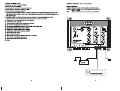
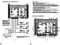
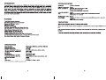
INTRODUCTION
Congratulations on your purchase of a BOSS Audio Systems Electronic Crossover. This product
has been designed and built to deliver excellent sound quality and long lasting high performance.
We are sure you'll enjoy listening to your favorite music with this BOSS component in your car
audio system. For best results please consult a professional car stereo installer for application
advice or troubleshooting. To guarantee top performance we recommend using The BOSS Link
installation accessories such as RCA interconnects, power cable, and speaker wire. Thank you
for choosing BOSS Audio Systems products for your autosound system. We can't change the world,
but we can make it sound better.
FEATURES
Three Way Electronic Crossover
Gold Pleated RCA and Power Connectors
Remote On/ Off Power Control
LED Power Indicator
Switching Power Supply
Low-Noise High Slew Rate Audio Grade Op Amps
Fully Adjustable Low and High Pass Output Levels
Phase Reverse Volume on Low Pass
Infinitely Variable Low Pass Crossover
Infinitely Variable High Pass Crossover
Frequency Multiplier Switch on Front High Pass Crossover
Low Pass Stereo Channel Selector for mixed or Direct Low Pass Inputs
Bass Boost Volume with Variable Frequency Volume.
SPECIFICATIONS
Input Impedance Front & Rear: 39K-Ohm, Low Pass: 10K-Ohm
Maximum Input Level 4.5V RMS
Maximum Output Level
High Pass Crossover, 12dB/octave
Low Pass Crossover, 12dB/octave
Low Boost
Gain Structure
Frequency Response, Low Pass
Frequency Response, High Pass
Signal-to-Noise Ratio
THD
Dimensions
9V RMS
Front: 50Hz-5KHz; Rear: 45Hz -1.6KHz
40Hz-250Hz
Oto +18dB
Variable, o to +6dB
5Hz - 500Hz, -3dB
F: 50Hz-50KHz, -3dB; R: 45Hz-50KHz, -3dB
>95dB
<0.01%
8 3/4"(W) x 7 1/2"(L) x 1 1/4"(H)
Features and specifications subject to change without notice.
TROUBLE SHOOTING
Symptom Possible remedy:
Signal Processor Check:
does not turn on. "Remote Turn-On wire has (+) 12V
*(+) 12V wire has (+) 12V
*Ground wire is properly connected:
Levelofsoundis Check:
low. *Wiring is not loose or cables misconnected/disconnected
*RCA cables are not faulty
Background noise Check:
is too high. *Wiring is not loose or cables misconnected/disconnected - ground is
important
*RCA cables are not faulty
PRECAUTIONS
Enjoy your system, but use it wisely and safely!
*Never drive with the volume raised so high you cannot hear what is occuring in traffic around
you.
* Be ware that repeated exposure to excessive volume levels can permanently damage your
hearing!
* Keep all electronics away from moisture, dust, extreme heat or extreme vibrations.
© OS N =
8.
9.
10
11
12
13
. Power Terminal (+12V).
. Remote Turn-On Terminal (REM).
. Ground Terminal (GND).
. Subwoofer Low Pass Frequency Control.
. Bass Boost Level Control (TO +18dB)
. Bass Boost Frequency Control
. Low Pass Mode Switch: Allows Low Pass Channel to receive signal from either the mix
of Front and Rear inputs or from Low Pass Inputs directly (when head unit has appropriate
5th / 6th outputs.
Variable Phase Selector Control: Use this control to select output phase for the
subwoofer channel to provide best time alignment and stereo imaging.
Subwoofer (Low Pass) Output Level Control
.LED Power On Indicator
. Rear Channel High Pass Frequency Control
. Rear Channel Output Level Control
. Frequency Multiplier Switch, Front High Pass Crossover
14. Front High Pass Frequency Control
15. Front High Pass Output Level Control
16. Subwoofer Low Pass Channel Inputs
17
18
19
20
21
22.
. Front Channel Inputs
. Rear Channel Inputs
. Subwoofer Low Pass Channel Output Terminals.
. Rear Channel Output Terminals.
. Front Channel Output Terminals.
Fuse
WIRING DIAGRAM : Power Connection
Power connection
* B+(12V) : Connect a red wire to the car battery or other power source.
* REMOTE: Connect an orange wire to remote activating (12V DC)wire of car
stereo or equalizer.
*GND : Connect a black wire to the car chassis for ground connection.
®
SUBWOOFER crossover — REAR FRONT
«20 e e BASS BOOST 100 BREA cuen CROSSOVER
N e ° e x10
. ° , ° 50 200 O POWER Р SET
. © ° o (50-500Hz)
40 250 0 +18dB 25 250 FREQ
LOW PASS LEVEL FREQUENCY MULTIPLIER
FREQUENCY | HIGH PASS HIGH PASS
FREQUENCY FREQUENCY
PHASE 1
. © e 350 . ® ©
100 700
. © . .
== DIRECT . o . e
0 180° 45 1.6k 0 00
INPUT MODE Hz E Y 500
SUBWOOFER REAR FRONT
OUTPUT LEVEL OUTPUT LEVEL OUTPUT LEVEL
3way electronic ° 2 - ° - °
crossover o © © °
A min max min max min max
| Лол | —= | пни
I N
© © © L © © ©
© © © © © ©
SUBWOOFER FRONT REAR SUBWOOFER REAR FRONT 12V+ REM GROUND FUSE
[outputs |
mn ~~
BATTERY
O
CIC JC JCJ
WIRING DIAGRAM: Two Way (BIAMP) Operation INSTALLATION
1. Find a suitable location in the vehicle to mount the crossover.
2. Bolt the crossover to the mounting surface.
© © 3. Using the screw terminals provided, connect minimum 16 gauge wire from the power,
в Ground and remote terminals. Connect the shortest possible wire to a chassis ground point. The (+)
12V connection should be made directly to the car battery, and the remote should be connected to
ь the Remote Turn On Lead of your head unit. When connecting directly to the battery, installa 3A
Fuse within 18 inches of the battery terminal.
SUBWOOFER crossover REAR FRONT 4. Connectall line inputs and outputs using high-quality RCA cables.
AN. AS AS y | 0 5. Recheck all connections before powering up.
| A . O O ren Di. 6. Setall level controls to their minimum positions and set all crossover controls, switches, etc. To
до PASS a REC OY Uli PASS vien Mee the desired frequency or position.
PHASE FREQUENCY FREQUENCY 7. Once the system is powered up, set the volume control on the head unit to a moderate level where
Lune AN. 100 300 JAS. your normal speaking voice can be heard while the musicis playing.
— DIRECT ©; (a O: 8. Further fine tuning of the various controls may be necessary to obtain the desired results.
INPUT MODE ’ | 18 * " ve E " ни 9. When unsure about installation or system tuning, please consult an authorized BOSS AUDIO dealer.
SUBWOOFER REAR FRONT
OUTPUT LEVEL OUTPUT LEVEL OUTPUT LEVEL
BX>> O: (СЭ (EN,
way clectronic . . . e . e
Ч crossover | min y MA Ni ma _ Nin | тах
о о o14d 5% CONTROLS AND OPERATION
© © © в © © © | |
SUBWOOFER FRONT REAR SUBWOOFER REAR FRONT 12V+ REM GROUND FUSE J
© IM JM N Г [elele] = ©
Ifrequired, the Left Front
and Left Rear Inputs may
be paralleled with a
Y-adaptor ( same for the FRONT CHANNEL
Right Front and Right Rear AMPLIFIER a
Inputs). These Y-adaptors
can then be connected to SET ey = | (600 sr
Either the Front Or the Rear um (DCE SPEAKERS . . | M some
outputs of the head unit. LOW Ass , LEVEL EC OY MULTIPLIER
FREQUENCY |
REAR CHANNEL —d
AMPLIFIER Æ 7
7 MIXED . . 4
e 7 e — DIRECT
—[[i “E EN ID INPUT MODE „50 sw
OPTIONAL 5TH OUTPUT — — SPEAKERS 8 |
FRONT
9 ! OUTPUT LEVEL
FRONT OUTPUT SUBWOOFER CHANNEL <= =»> . . .
AMPLIFIER 3way electronic 3 - , >
; AE ; crossover min - min
REAR OUTPUT o — | —
o © © L © ©
SUBWOOFERS © © 9 SUBWOOFER E FRONT 12V+ REM _ GROUND
IS
CIO Use the Sub Inputs if the head unit has a pair of
Low Pass Outputs. In this case, set the Low Pass Mode
Selector to the DIRECT position
Head Unit