1
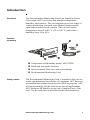
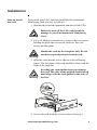
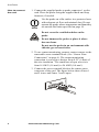
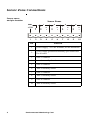
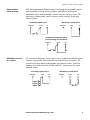
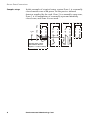
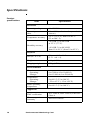
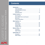
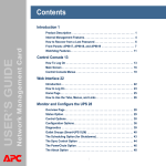
Environmental
Monitoring Card
AP9612TH
Installation and
Quick-Start Manual
®
Contents
Introduction . . . . . . . . . . . . . . . . . . . . . . . . . . . . . 1
Overview . . . . . . . . . . . . . . . . . . . . . . . . . . . . . 1
Product inventory . . . . . . . . . . . . . . . . . . . . . . 1
Safety notice . . . . . . . . . . . . . . . . . . . . . . . . . . . 1
Your inspection and warranty
responsibilities . . . . . . . . . . . . . . . . . . . . . . . . 2
Hardware requirements . . . . . . . . . . . . . . . . . . 2
Data reporting . . . . . . . . . . . . . . . . . . . . . . . . . 2
Installation . . . . . . . . . . . . . . . . . . . . . . . . . . . . . . 3
How to install the card . . . . . . . . . . . . . . . . . . . 3
How to connect the card . . . . . . . . . . . . . . . . . 4
How to test the card. . . . . . . . . . . . . . . . . . . . . 5
Periodic maintenance . . . . . . . . . . . . . . . . . . . . 5
Sensor Zone Connections . . . . . . . . . . . . . . . . . . . 6
Sensor zones and pin location. . . . . . . . . . . . . . 6
Connection information . . . . . . . . . . . . . . . . . . 7
Multiple sensors in a zone. . . . . . . . . . . . . . . . . 7
Sample setup . . . . . . . . . . . . . . . . . . . . . . . . . . 8
Sensor Selection . . . . . . . . . . . . . . . . . . . . . . . . . . 9
Dry contact sensors . . . . . . . . . . . . . . . . . . . . . 9
Normally open and normally closed sensors . . . 9
Detectors that need power . . . . . . . . . . . . . . . . 9
For more information . . . . . . . . . . . . . . . . . . . . 9
Specifications . . . . . . . . . . . . . . . . . . . . . . . . . . . 10
Warranty and Service . . . . . . . . . . . . . . . . . . . . . 11
Limited warranty. . . . . . . . . . . . . . . . . . . . . . . 11
Warranty limitations . . . . . . . . . . . . . . . . . . . . 11
Obtaining service . . . . . . . . . . . . . . . . . . . . . . 11
Environmental Monitoring Card
Contents
Life Support Policy . . . . . . . . . . . . . . . . . . . . . . . 13
General policy. . . . . . . . . . . . . . . . . . . . . . . . . 13
Examples of life-support devices . . . . . . . . . . . 13
ii
Environmental Monitoring Card
Introduction
Overview
The Environmental Monitoring Card is an American Power
Conversion (APC) accessory that monitors temperature,
humidity, and contacts. The card supports up to four zones of
contact monitoring, and each zone supports both normally
open and normally closed contacts. The card will report
temperatures from 0 to 60° C (32 to 140° F) and relative
humidity from 10 to 90%.
Product
inventory
Safety notice
Temperature and humidity probe (AP9512TH)
Hook and loop probe fasteners
Screw terminal block for contact monitoring
Environmental Monitoring Card
The Environmental Monitoring Card is intended solely for use
in the supplementary surveillance of equipment. APC does not
recommend this product for protection of life or property. APC
will not knowingly sell the card for use in such applications.
APC disclaims all liability arising out of improper use of the
card. Use the card only as described in this documentation.
Environmental Monitoring Card
1
Introduction
Your inspection
and warranty
responsibilities
Inspect the card immediately, and notify the carrier and the
seller if there is any shipping damage. Fill out and return the
enclosed warranty card before you begin using the unit.
Hardware
requirements
The card requires an APC device with an available accessory
slot. This device can be a UPS with an accessory slot or an
Expansion Chassis with a supporting UPS.
Data reporting
The card also requires some means of reporting its data. The
following APC products can report data for the card:
• Network Management Card (AP9617, AP9618, AP9619)
• Out-of-Band Management Card (AP9608)
• PowerChute Business Edition and PowerChute Network
Shutdown UPS power management and diagnostic
software
• PowerNet Adapter
• Other APC products that support Web-based or SNMP
management.
2
Environmental Monitoring Card
Installation
How to install
the card
First install your UPS, and then install the Environmental
Monitoring Card in a slot, as follows:
1. Shut down protected equipment and turn off the UPS.
Warning
Failure to turn off the UPS could result in
damage to your Environmental Monitoring
Card.
2. Use a #2 Phillips screwdriver to remove the two screws
holding the plate that covers the card slot. Save the
screws and the plate.
Handle the card by the faceplate only. Do not
touch the exposed printed circuit board.
Warning
3. Slide the card into the slot as shown in the following
figure. The faceplate of the card should be flush with the
front of the card slot.
Warning
Inserting the card upside down can damage
the card. The sides of the printed circuit board
must align with the card guides in the sides of
the slot.
4. Secure the card with the screws removed in step 2.
Environmental Monitoring Card
3
Installation
How to connect
the card
1. Connect the supplied probe to probe connector 1 on the
card. Place the probe using the supplied hook and loop
fasteners, if needed.
Note
Use the probe on a flat surface in a protected area
with adequate air flow and minimal dust. Do not
operate the probe where temperature and humidity
are outside the limits specified on page 10.
Do not cover the ventilation holes on the
probe.
Warning
Do not immerse the probe or place it where
dew can form.
Do not use the probe in an environment with
chlorine gas or insecticides.
2. To use contact monitoring, connect contact sensors to the
removable screw terminal block. (See “Sensor Zone
Connections” on page 6). The contact monitoring
connection is a two-piece design. Strip 0.25" (6 mm) of
the wire insulation . The connector accepts wire sizes
from 14 AWG (1.6 mm²) to 26 AWG (0.4 mm²).
3. Connect the screw terminal block to the sensor zones
connector of the card. The figure below shows Zones 1
and 2 in use and Zones 3 and 4 open.
4
Environmental Monitoring Card
Installation
How to test the
card
1. Use your data reporting system to confirm that the card is
working. (See page 2.)
2. Check that the probe is connected to probe connector 1.
The card should transmit temperature and humidity
values to the reporting system.
3. Activate each sensor according to the sensor
manufacturer’s recommendation. Use the data reporting
system to verify that each sensor operates.
Periodic
maintenance
The Environmental Monitoring Card requires the following
maintenance:
• Test the card periodically according to the sensor
manufacturer’s recommendations. See “How to test the
card” .
• Clean the probe whenever there is a visible buildup of
dust. Gently brush or vacuum off the dust. Do not blow
any type of compressed air into the probe.
Environmental Monitoring Card
5
Sensor Zone Connections
Sensor zones
and pin location
Sensor Zones
GND
+12V
1
6
1
N
O
C
O
M
2
3
2
N
C
C
O
M
4
5
3
N
C
C
O
M
6
7
4
N
C
C
O
M
N
C
8
9
10
Pin
Function
1
power supply, +12 VDC nominal, 60 mA maximum
2
power supply ground and normally open connection
for all zones
3
zone 1 common
4
zone 1 normally closed
5
zone 2 common
6
zone 2 normally closed
7
zone 3 common
8
zone 3 normally closed
9
zone 4 common
10
zone 4 normally closed
Environmental Monitoring Card
Sensor Zone Connections
Connection
information
The Environmental Monitoring Card supports normally open
and normally closed loop systems, and allows mixing of
normally open and normally closed sensors on any zone. Do
not cross-connect the card’s sensors with sensors from any
other system.
Normally Open Zone
GND/NO
COM
Normally Closed Zone
NC
GND/NO
NC
COM
Combined Normally Open
and Normally Closed Zone
GND/NO
Multiple sensors
in a zone
COM
NC
To use more than one sensor on a zone, connect normally open
sensors in parallel and normally closed sensors in series. To
avoid receiving alarm indications on unused zones, install a
jumper wire between the COM and NC connectors for each
unused zone.
Normally Open Zone
GND/NO
COM
NC
Environmental Monitoring Card
Normally Closed Zone
GND/NO
COM
NC
7
Sensor Zone Connections
Sample setup
In this example of a typical setup, system Zone 1 is a normally
closed motion zone with power for the passive infrared
detector supplied by the card. Zone 2 is a normally open zone,
Zone 3 is a combination of a normally open and normally
closed zone, and Zone 4 is not used.
Zone 1
G
N
D
+12V
N
O
1
2
+
–
C
O
M
3
N
C
4
Zone 2
C
O
M
5
NC
Normally closed, passive,
Infared Motion Detector
(requires +12 VDC at 20mA)
8
Environmental Monitoring Card
N
C
6
Zone 4
Zone 3
C
O
M
7
N
C
C
O
M
N
C
8
9
10
Sensor Selection
Dry contact
sensors
The Environmental Monitoring Card may be used with any dry
contact closure sensors. The card’s sensor inputs monitor
circuits that have no voltage potential of their own.
Warning
Connecting the card’s sensor inputs to any circuit
other than a dry closure type will void the
warranty and may result in damage to the card.
Normally open
and normally
closed sensors
Any normally open (NO) or normally closed (NC) dry contact
sensor may be used with the card. Such sensors include:
• magnetic contact switches
• window foils
• tamper switches
• heat detectors
• water sensors
• pressure sensors
Detectors that
need power
The card provides 12 VDC at up to 60 mA at pins 1 and 2 of
the sensor zones connector for sensors that require power.
These include:
• passive infrared (body heat) detectors
• smoke sensors
• photo relay detectors
For more
information
For a list of supported sensors, go to the APC Web site at
www.apc.com/support. Follow the link to Knowledge Base
and enter sensors in the search box at the bottom of the page.
You may also call APC Customer Support at a number on the
back cover for more information.
Environmental Monitoring Card
9
Specifications
Product
specifications
Item
Specification
Electrical
Operating voltage
16 – 27 VDC
Operating current
draw
30 mA DC (exclusive of any attached
sensors)
Temperature accuracy
± 2° C (±3.6° F) from 0 to 40° C
(32 to 104° F)
± 8% RH, 10 to 90% RH
at 25° C (77° F)
Humidity accuracy
± 8% RH, 30 to 80 % RH
from 15 to 30° C (from 59 to 95° F)
Physical
Size (h × w × d)
3.8 cm × 10.2 × 10.2
(1.5 i × n4 × 4)
Weight
140 g (0.3 lb)
Shipping weight
320 g (0.7 lb)
Environmental
Elevation:
Operating:
Storage:
0 to 3000 m (0 to 10,000 ft)
0 to 15 000 m (0 to 50,000 ft)
Temperature:
Operating:
Storage:
0 to 40° C (32 to 104° F)
– 25 to 65° C (–13 to 149° F)
Probe operating
temperature
0 to 60° C (32 to 140° F)
Approvals
10
EMC verification
FCC Class A, DOC Class A, EN55022
Class A
Electromagnetic
immunity
EN55024 verified
Environmental Monitoring Card
Warranty and Service
Limited
warranty
APC warrants the Environmental Monitoring Card to be free
Warranty
limitations
Except as provided herein, APC makes no warranties,
express or implied, including warranties of merchantability
and fitness for a particular purpose. Some jurisdictions do
not permit limitation or exclusion of implied warranties;
therefore, the aforesaid limitation(s) or exclusion(s) may not
apply to the purchaser.
from defects in materials and workmanship for a period of two
years from the date of purchase. Its obligation under this
warranty is limited to repairing or replacing, at its own sole
option, any such defective products. This warranty does not
apply to equipment that has been damaged by accident,
negligence, or misapplication or has been altered or modified
in any way. This warranty applies only to the original
purchaser.
Except as provided above, in no event will APC be liable for
direct, indirect, special, incidental, or consequential
damages arising out of the use of this product, even if
advised of the possibility of such damage.
Specifically, APC is not liable for any costs, such as lost profits
or revenue, loss of equipment, loss of use of equipment, loss of
software, loss of data, costs of substitutes, claims by third
parties, or otherwise. This warranty gives you specific legal
rights and you may also have other rights, which vary
according to jurisdiction.
Obtaining
service
To obtain support for problems with your Environmental
Monitoring Card:
0
1. Note the serial number and date of purchase. These may
be located on the bottom of your card.
2. Contact Customer Support at a phone number on the
back cover of this document. A technician will try to
help you solve the problem by phone.
3. If you must return the product, the technician will give
you a return material authorization (RMA) number. If the
warranty expired, you will be charged for repair or
Environmental Monitoring Card
11
Warranty and Service
replacement.
4. Pack the unit carefully. The warranty does not cover
damage sustained in transit. Enclose a letter with your
name, address, RMA number and daytime phone
number; a copy of the sales receipt; and a check as
payment, if applicable.
5. Mark the RMA number clearly on the outside of the
shipping carton.
6. Ship by insured, prepaid carrier to the address provided
by the Customer Support technician.
12
Environmental Monitoring Card
Life Support Policy
General policy
American Power Conversion (APC) does not recommend the
use of any of its products in the following situations:
• In life-support applications where failure or malfunction
of the APC product can be reasonably expected to cause
failure of the life-support device or to affect significantly
its safety or effectiveness.
• In direct patient care.
APC will not knowingly sell its products for use in such
applications unless it receives in writing assurances
satisfactory to APC that (a) the risks of injury or damage have
been minimized, (b) the customer assumes all such risks, and
(c) the liability of American Power Conversion is adequately
protected under the circumstances.
a0
Examples of lifesupport devices
The term life-support device includes but is not limited to
neonatal oxygen analyzers, nerve stimulators (whether used for
anesthesia, pain relief, or other purposes), autotransfusion
devices, blood pumps, defibrillators, arrhythmia detectors and
alarms, pacemakers, hemodialysis systems, peritoneal dialysis
systems, neonatal ventilator incubators, ventilators (for adults
and infants), anesthesia ventilators, infusion pumps, and any
other devices designated as “critical” by the U.S. FDA.
Hospital-grade wiring devices and leakage current protection
may be ordered as options on many APC UPS systems. APC
does not claim that units with these modifications are certified
or listed as hospital-grade by APC or any other organization.
Therefore these units do not meet the requirements for use in
direct patient care.
Environmental Monitoring Card
13
®
APC Worldwide Customer Support
Customer support for this or any other APC product is available at no charge in any of the
following ways:
•
Visit the APC Web site to find answers to frequently asked questions (FAQs), to
access documents in the APC Knowledge Base, and to submit customer support
requests.
– www.apc.com (Corporate Headquarters)
Connect to localized APC Web sites for specific countries, each of which
provides customer support information.
– www.apc.com/support/
Global support with FAQs, knowledge base, and e-support.
•
Contact an APC Customer Support center by telephone or e-mail.
– Regional centers:
APC headquarters U.S.,
Canada
–
(1)(800)800-4272 (toll free)
Latin America
(1)(401)789-5735 (USA)
Europe, Middle East, Africa
(353)(91)702020 (Ireland)
Japan
(0) 35434-2021
Local, country-specific centers: go to www.apc.com/support/contact for
contact information.
Contact the APC representative or other distributor from whom you purchased your APC
product for information on how to obtain local customer support.
Entire contents copyright © 2003 American Power Conversion. All rights
reserved. Reproduction in whole or in part without permission is prohibited.
APC, the APC logo, PowerChute, and PowerNet are trademarks of American
Power Conversion Corporation and may be registered in some jurisdictions. All
other trademarks, product names, and corporate names are the property of their
respective owners and are used for informational purposes only.
990-0129B
02/2003