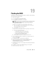
1
OM_Book.book Page 1 Tuesday, September 25, 2012 2:30 PM
Dell XPS 13 Owner’s Manual
Computer model: L321x/L322x
Regulatory model: P29G
Regulatory type: P29G001/P29G002
OM_Book.book Page 2 Tuesday, September 25, 2012 2:30 PM
Notes, Cautions, and Warnings
NOTE: A NOTE indicates important information that helps you make better use of
your computer.
CAUTION: A CAUTION indicates potential damage to hardware or loss of data if
instructions are not followed.
WARNING: A WARNING indicates a potential for property damage, personal
injury, or death.
____________________
Information in this document is subject to change without notice.
© 2012 Dell Inc. All rights reserved.
Reproduction of these materials in any manner whatsoever without the written permission of Dell Inc.
is strictly forbidden.
Trademarks used in this text: Dell™, the DELL logo, and XPS™ are trademarks of Dell Inc.;
are either trademarks or registered
Microsoft®, Windows® and the Windows start button logo
trademarks of Microsoft corporation in the United States and/or other countries; Bluetooth® is a
registered trademark owned by Bluetooth SIG, Inc. and is used by Dell under license.
Other trademarks and trade names may be used in this document to refer to either the entities claiming
the marks and names or their products. Dell Inc. disclaims any proprietary interest in trademarks and
trade names other than its own.
Regulatory model: P29G
2012 - 09
Regulatory type: P29G001/P29G002
Rev. A00
OM_Book.book Page 3 Tuesday, September 25, 2012 2:30 PM
Contents
1
Before You Begin .
. . . . . . . . . . . . . . . . . . .
Turn Off Your Computer and Connected Devices
Safety Instructions .
. . . . .
. . . . . . . . . . . . . . . . . . .
Recommended Tools .
. . . . . . . . . . . . . . . . . .
2
After Working Inside Your Computer .
3
Base Cover
9
10
10
. . .
11
. . . . . . . . . . . . . . . . . . . . . . .
13
Removing the Base Cover
. . . . . . . . . . . . . . . .
14
. . . . . . . . . . . . . . . . .
15
. . . . . . . . . . . . . . . . . . . . . .
15
Power-Light Board
Prerequisites .
13
. . . . . . . . . . . . . . .
Replacing the Base Cover .
4
9
Removing the Power-Light Board .
. . . . . . . . . . .
15
Replacing the Power-Light Board .
. . . . . . . . . . .
16
. . . . . . . . . . . . . . . . . . . . . .
16
Postrequisites
Contents
3
OM_Book.book Page 4 Tuesday, September 25, 2012 2:30 PM
5
Battery .
. . . . . . . . . . . . . . . . . . . . . . . . .
Prerequisites .
. . . . . . . . . . . . . . . . . .
17
Replacing the Battery
. . . . . . . . . . . . . . . . . .
18
. . . . . . . . . . . . . . . . . . . . . .
18
Speakers
. . . . . . . . . . . . . . . . . . . . . . . .
Prerequisites .
19
Replacing the Speakers
. . . . . . . . . . . . . . . . .
22
. . . . . . . . . . . . . . . . . . . . . .
22
Wireless Mini-Card
. . . . . . . . . . . . . . . . . . . . . .
23
23
. . . . . . . . . . . . . . . .
24
Replacing the Mini-Card .
. . . . . . . . . . . . . . . .
25
. . . . . . . . . . . . . . . . . . . . . .
26
Solid-State Drive
Prerequisites .
Contents
. . . . . . . . . . . . . . . .
Removing the Mini-Card .
Postrequisites
4
19
. . . . . . . . . . . . . . . . .
Prerequisites .
8
. . . . . . . . . . . . . . . . . . . . . .
19
Removing the Speakers
Postrequisites
7
17
Removing the Battery
Postrequisites
6
. . . . . . . . . . . . . . . . . . . . . .
17
. . . . . . . . . . . . . . . . . .
. . . . . . . . . . . . . . . . . . . . . .
27
27
Removing the Solid-State Drive .
. . . . . . . . . . . .
27
Replacing the Solid-State Drive .
. . . . . . . . . . . .
28
OM_Book.book Page 5 Tuesday, September 25, 2012 2:30 PM
Postrequisites
9
Heat Sink .
. . . . . . . . . . . . . . . . . . . . . .
28
. . . . . . . . . . . . . . . . . . . . . . . .
29
Prerequisites .
. . . . . . . . . . . . . . . . . . . . . .
29
Removing the Heat Sink .
. . . . . . . . . . . . . . . .
29
Replacing the Heat Sink .
. . . . . . . . . . . . . . . .
30
. . . . . . . . . . . . . . . . . . . . . .
30
. . . . . . . . . . . . . . . . . . . . . . . . . . . . .
31
Postrequisites
10 Fan .
Prerequisites .
. . . . . . . . . . . . . . . . . . . . . .
31
Removing the Fan
. . . . . . . . . . . . . . . . . . . .
31
Replacing the Fan
. . . . . . . . . . . . . . . . . . . .
33
. . . . . . . . . . . . . . . . . . . . . .
33
Postrequisites
11 Power-Adapter Connector
Prerequisites .
. . . . . . . . . . .
35
. . . . . . . . . . . . . . . . . . . . . .
35
Removing the Power-Adapter Connector .
. . . . . . .
35
Replacing the Power-Adapter Connector .
. . . . . . .
37
. . . . . . . . . . . . . . . . . . . . . .
38
Postrequisites
Contents
5
OM_Book.book Page 6 Tuesday, September 25, 2012 2:30 PM
12 I/O Board
. . . . . . . . . . . . . . . . . . . . . . . .
Prerequisites .
. . . . . . . . . . . . . . . . . . . . . .
. . . . . . . . . . . . . . . . .
40
Replacing the I/O Board
. . . . . . . . . . . . . . . . .
40
. . . . . . . . . . . . . . . . . . . . . .
41
13 System Board .
Prerequisites .
. . . . . . . . . . . . . . . . . . . .
. . . . . . . . . . . . . . . . . . . . . .
43
43
Removing the System Board .
. . . . . . . . . . . . . .
44
Replacing the System Board .
. . . . . . . . . . . . . .
46
. . . . . . . . . . . . . . . . . . . . . .
47
Postrequisites
Entering the Service Tag in BIOS
14 Coin-Cell Battery
Prerequisites .
. . . . . . . . . . . . . . . . . . . . . .
. . . . . . . . . . . . .
49
49
50
50
. . . . . . . . . . . . . . . . . . . . . .
51
15 Display Assembly .
Prerequisites .
47
. . . . . . . . . . . .
Replacing the Coin-Cell Battery .
Postrequisites
. . . . . . . . . . . .
. . . . . . . . . . . . . . . . . .
Removing the Coin-Cell Battery
. . . . . . . . . . . . . . . . .
. . . . . . . . . . . . . . . . . . . . . .
Removing the Display Assembly.
Contents
39
Removing the I/O Board
Postrequisites
6
39
. . . . . . . . . . . .
53
53
53
OM_Book.book Page 7 Tuesday, September 25, 2012 2:30 PM
Replacing the Display Assembly
. . . . . . . . . . . .
56
. . . . . . . . . . . . . . . . . . . . . .
57
. . . . . . . . . . . . . . . . . . . . . . . . .
59
Postrequisites
16 Keyboard
Prerequisites .
. . . . . . . . . . . . . . . . . . . . . .
Removing the Keyboard
. . . . . . . . . . . . . . . . .
61
. . . . . . . . . . . . . . . . . . . . . .
61
17 Palm-Rest Assembly
Prerequisites .
60
. . . . . . . . . . . . . . . .
Replacing the Keyboard .
Postrequisites
59
. . . . . . . . . . . . . . . .
63
. . . . . . . . . . . . . . . . . . . . . .
63
Removing the Palm-Rest Assembly .
. . . . . . . . . .
64
Replacing the Palm-Rest Assembly .
. . . . . . . . . .
64
. . . . . . . . . . . . . . . . . . . . . .
65
Postrequisites
18 System Setup .
Overview .
. . . . . . . . . . . . . . . . . . . . .
67
. . . . . . . . . . . . . . . . . . . . . . . .
67
. . . . . . . . . . . . . . . . .
67
. . . . . . . . . . . . . . . . . .
73
Entering System Setup .
19 Flashing the BIOS
Contents
7
OM_Book.book Page 8 Tuesday, September 25, 2012 2:30 PM
8
Contents
OM_Book.book Page 9 Tuesday, September 25, 2012 2:30 PM
1
Before You Begin
Turn Off Your Computer and Connected Devices
CAUTION: To avoid losing data, save and close all open files and exit all open
programs before you turn off your computer.
1 Save and close all open files and exit all open programs.
2 Follow the instructions to shut down your computer based on the operating system installed on your computer.
Windows 8:
Move your mouse pointer to the upper-right or lower-right corner of the
screen to open the Charms sidebar, and click Settings→ Power→
Shutdown.
Windows 7:
Click Shut
and click Shut down.
Microsoft Windows shuts down and then the computer turns off.
NOTE: If you are using a different operating system, see the documentation of
your operating system for shut-down instructions.
3 Disconnect your computer and all attached devices from their electrical outlets.
4 Disconnect all telephone cables, network cables, and attached devices from your computer.
5 Press and hold the power button for 5 seconds, after the computer is unplugged, to ground the system board.
Before You Begin
9
OM_Book.book Page 10 Tuesday, September 25, 2012 2:30 PM
Safety Instructions
Use the following safety guidelines to protect your computer from potential
damage and ensure your personal safety.
WARNING: Before working inside your computer, read the safety information
that shipped with your computer. For additional safety best practices information,
see the Regulatory Compliance Homepage at dell.com/regulatory_compliance.
WARNING: Disconnect all power sources before opening the computer cover or
panels. After you finish working inside the computer, replace all covers, panels,
and screws before connecting to the power source.
CAUTION: To avoid damaging the computer, ensure that the work surface is flat
and clean.
CAUTION: To avoid damaging the components and cards, handle them by their
edges and avoid touching pins and contacts.
CAUTION: Only a certified service technician is authorized to remove the
computer cover and access any of the components inside the computer. See the
safety instructions for complete information about safety precautions, working
inside your computer, and protecting against electrostatic discharge.
CAUTION: Before touching anything inside your computer, ground yourself by
touching an unpainted metal surface, such as the metal at the back of the
computer. While you work, periodically touch an unpainted metal surface to
dissipate static electricity, which could harm internal components.
CAUTION: When you disconnect a cable, pull on its connector or on its pull-tab,
not on the cable itself. Some cables have connectors with locking tabs or
thumb-screws that you must disengage before disconnecting the cable. When
disconnecting cables, keep them evenly aligned to avoid bending any connector
pins. When connecting cables, ensure that the connectors and ports are correctly
oriented and aligned.
CAUTION: To disconnect a network cable, first unplug the cable from your
computer and then unplug the cable from the network device.
Recommended Tools
The procedures in this document may require the following tools:
10
•
Torx 5 screwdriver
•
Phillips screwdriver
•
Plastic scribe
Before You Begin
OM_Book.book Page 11 Tuesday, September 25, 2012 2:30 PM
2
After Working Inside Your Computer
After you complete replacement procedures, ensure the following:
• Replace all screws and ensure that no stray screws remain inside
your computer
• Connect any external devices, cables, cards, and any other part(s) you removed before working on your computer
• Connect your computer and all attached devices to their electrical outlets
CAUTION: Before turning on your computer, replace all screws and ensure
that no stray screws remain inside the computer. Failure to do so may damage
your computer.
After Working Inside Your Computer
11
OM_Book.book Page 12 Tuesday, September 25, 2012 2:30 PM
12
After Working Inside Your Computer
OM_Book.book Page 13 Tuesday, September 25, 2012 2:30 PM
3
Base Cover
WARNING: Before working inside your computer, read the safety information that
shipped with your computer and follow the steps in "Before You Begin" on page 9.
For additional safety best practices information, see the Regulatory Compliance
Homepage at dell.com/regulatory_compliance.
Removing the Base Cover
1 Close the display and turn the computer over.
2 Using a Torx 5 screwdriver, remove the screws that secure the base cover to
the palm-rest assembly.
3 Using your fingertips, lift the base cover starting from the back of your computer.
4 Remove the base cover off the palm-rest assembly.
1
1
base cover
2
2
screws (10)
Base Cover
13
OM_Book.book Page 14 Tuesday, September 25, 2012 2:30 PM
Replacing the Base Cover
1 Align the base cover with the palm-rest assembly and press the base cover
into place.
2 Using a Torx 5 screwdriver, replace the screws that secure the base cover to
the palm-rest assembly.
3 Follow the instructions in "After Working Inside Your Computer" on page 11.
14
Base Cover
OM_Book.book Page 15 Tuesday, September 25, 2012 2:30 PM
4
Power-Light Board
WARNING: Before working inside your computer, read the safety information that
shipped with your computer and follow the steps in "Before You Begin" on page 9.
For additional safety best practices information, see the Regulatory Compliance
Homepage at dell.com/regulatory_compliance.
Prerequisites
1 Remove the base cover. See "Removing the Base Cover" on page 13.
Removing the Power-Light Board
1 Lift the connector latch and pull the pull-tab to disconnect the
power-light board cable from the connector on the I/O board.
2 Remove the screw that secures the power-light board to the
palm-rest assembly.
3 Lift the power-light board off the palm-rest assembly.
1
2
3
1
screw
3
power-light board
2
power-light board cable
Power-Light Board
15
OM_Book.book Page 16 Tuesday, September 25, 2012 2:30 PM
Replacing the Power-Light Board
1 Align the screw hole on the power-light board with the screw hole on the palm-rest assembly.
2 Replace the screw that secures the power-light board to the palm-rest assembly.
3 Slide the power-light board cable into the system-board connector and press down on the connector latch to secure the cable.
Postrequisites
1 Replace the base cover. See "Replacing the Base Cover" on page 14.
2 Follow the instructions in "After Working Inside Your Computer" on page 11.
16
Power-Light Board
OM_Book.book Page 17 Tuesday, September 25, 2012 2:30 PM
5
Battery
WARNING: Before working inside your computer, read the safety information that
shipped with your computer and follow the steps in "Before You Begin" on page 9.
For additional safety best practices information, see the Regulatory Compliance
Homepage at dell.com/regulatory_compliance.
Prerequisites
1 Remove the base cover. See "Removing the Base Cover" on page 13.
2 Remove the power-light board. See "Removing the Power-Light Board" on
page 15.
Removing the Battery
1 Disconnect the battery cable from the system-board.
2 Remove the screws that secure the battery to the palm-rest assembly.
3 Lift the battery off the palm-rest assembly.
1
2
3
1
screws (8)
3
battery cable
2
battery
Battery
17
OM_Book.book Page 18 Tuesday, September 25, 2012 2:30 PM
Replacing the Battery
1 Align the screw holes on the battery with the screw holes on the palm-rest assembly.
2 Replace the screws that secure the battery to the palm-rest assembly.
3 Connect the battery cable to the system-board.
Postrequisites
1 Replace the power-light board. See "Replacing the Power-Light Board" on
page 16.
2 Replace the base cover. See "Replacing the Base Cover" on page 14.
3 Follow the instructions in "After Working Inside Your Computer" on page 11.
18
Battery
OM_Book.book Page 19 Tuesday, September 25, 2012 2:30 PM
6
Speakers
WARNING: Before working inside your computer, read the safety information that
shipped with your computer and follow the steps in "Before You Begin" on page 9.
For additional safety best practices information, see the Regulatory Compliance
Homepage at dell.com/regulatory_compliance.
Prerequisites
1 Remove the base cover. See "Removing the Base Cover" on page 13.
2 Remove the power-light board. See "Removing the Power-Light Board" on
page 15.
3 Remove the battery. See "Removing the Battery" on page 17.
Removing the Speakers
Left Speaker
1 Disconnect the I/O cable from the I/O board connector and
system-board connector.
1
2
3
1
I/O cable
3
system-board connector
2
I/O board connector
Speakers
19
OM_Book.book Page 20 Tuesday, September 25, 2012 2:30 PM
2 Disconnect the left-speaker cable from the I/O board connector.
3 Release the Mini-Card cables from the routing guide on the left speaker.
4 Remove the two screws that secure the left speaker to the
palm-rest assembly.
5 Lift the left speaker off the palm-rest assembly.
1
2
20
1
screws (2)
3
left-speaker cable
Speakers
3
2
routing guide
OM_Book.book Page 21 Tuesday, September 25, 2012 2:30 PM
Right Speaker
1 Disconnect the right-speaker cable from the system-board connector.
2 Remove the two screws that secure the right speaker to the
palm-rest assembly.
3 Lift the right speaker off the palm-rest assembly.
1
2
1
screws (2)
2
right-speaker cable
Speakers
21
OM_Book.book Page 22 Tuesday, September 25, 2012 2:30 PM
Replacing the Speakers
Left Speaker
1 Align the screw holes on the left speaker with the screw holes on the
palm-rest assembly.
2 Replace the two screws that secure the left speaker to the
palm-rest assembly.
3 Route the mini-card cables through the routing guide on the left speaker.
4 Connect the left-speaker cable to the I/O board connector.
5 Connect the I/O cable to the I/O board connector and
system-board connector.
Right Speaker
1 Align the screw holes on the right speaker with the screw holes on the
palm-rest assembly.
2 Replace the two screws that secure the right speaker to the
palm-rest assembly.
3 Connect the right-speaker cable to the system-board connector.
Postrequisites
1 Replace the battery. See "Replacing the Battery" on page 18.
2 Replace the power-light board. See "Replacing the Power-Light Board" on page 16.
3 Replace the base cover. See "Replacing the Base Cover" on page 14.
4 Follow the instructions in "After Working Inside Your Computer" on page 11.
22
Speakers
OM_Book.book Page 23 Tuesday, September 25, 2012 2:30 PM
7
Wireless Mini-Card
WARNING: Before working inside your computer, read the safety information that
shipped with your computer and follow the steps in "Before You Begin" on page 9.
For additional safety best practices information, see the Regulatory Compliance
Homepage at dell.com/regulatory_compliance.
NOTE: Dell does not guarantee compatibility or provide support for mini-cards from
sources other than Dell.
If you ordered a wireless mini-card with your computer, the card is
already installed.
Your computer has one half mini-card slot which supports a Wireless Local
Area Network (WLAN) + Bluetooth combo card.
Prerequisites
1 Remove the base cover. See "Removing the Base Cover" on page 13.
2 Remove the power-light board. See "Removing the Power-Light Board" on
page 15.
3 Remove the battery. See "Removing the Battery" on page 17.
4 Remove the right speaker. See "Removing the Speakers" on page 19.
CAUTION: When the mini-card is not in the computer, store it in protective
antistatic packaging. For more information, see "Protecting Against Electrostatic
Discharge" in the safety information that shipped with your computer.
Wireless Mini-Card
23
OM_Book.book Page 24 Tuesday, September 25, 2012 2:30 PM
Removing the Mini-Card
1 Disconnect the mini-card cables from the connectors on the mini-card.
1
1
mini-card cables (2)
2 Remove the screw that secures the mini-card to the system board.
3 Slide and remove the mini-card out of the system-board connector.
1
2
3
24
1
screw
3
system-board connector
Wireless Mini-Card
2
mini-card
OM_Book.book Page 25 Tuesday, September 25, 2012 2:30 PM
Replacing the Mini-Card
1 Remove the new mini-card from its packaging.
2 Align the notch on the mini-card with the tab in the system-board connector.
CAUTION: Use firm and even pressure to slide the mini-card into place. If you use
excessive force, you may damage the connector.
CAUTION: The connectors are keyed to ensure correct insertion. If you feel
resistance, check the connectors on the mini-card and on the system board,
and realign the mini-card.
CAUTION: To avoid damage to the mini-card, never place cables under the mini-card.
3 Insert the mini-card connector at a 45-degree angle into the
system-board connector.
4 Press the other end of the mini-card down into the slot on the system board and replace the screw that secures the mini-card to the system board.
5 Connect the mini-card cables to the connectors on the mini-card.
The following table provides the mini-card cable color scheme for the
Mini-Card supported by your computer.
Connectors on the Mini-Card
Mini-Card Cable Color
Scheme
WLAN + Bluetooth (2 cables)
Main WLAN + Bluetooth (white triangle)
white
Auxiliary WLAN + Bluetooth (black triangle) black
Wireless Mini-Card
25
OM_Book.book Page 26 Tuesday, September 25, 2012 2:30 PM
Postrequisites
1 Replace the right speaker. See "Replacing the Speakers" on page 22.
1 Replace the battery. See "Replacing the Battery" on page 18.
2 Replace the power-light board. See "Replacing the Power-Light Board" on page 16.
3 Replace the base cover. See "Replacing the Base Cover" on page 14.
4 Follow the instructions in "After Working Inside Your Computer" on page 11.
26
Wireless Mini-Card
OM_Book.book Page 27 Tuesday, September 25, 2012 2:30 PM
8
Solid-State Drive
WARNING: Before working inside your computer, read the safety information
that shipped with your computer and follow the steps in "Before You Begin" on
page 9. For additional safety best practices information, see the Regulatory
Compliance Homepage at dell.com/regulatory_compliance.
CAUTION: To avoid data loss, do not remove the solid-state drive while the
computer is On or in Sleep state.
CAUTION: Solid-state drives are extremely fragile. Exercise care when handling
the solid-state drive.
Prerequisites
1 Remove the base cover. See "Removing the Base Cover" on page 13.
2 Remove the power-light board. See "Removing the Power-Light Board" on
page 15.
3 Remove the battery. See "Removing the Battery" on page 17.
Removing the Solid-State Drive
1 Peel the tape that is adhered over the solid-state drive.
1
1
tape
2 Remove the screw that secures the solid-state drive to the system board.
Solid-State Drive
27
OM_Book.book Page 28 Tuesday, September 25, 2012 2:30 PM
3 Slide and remove the solid-state drive out of the system-board connector.
1
2
3
1
screw
3
solid-state drive
2
system-board connector
Replacing the Solid-State Drive
1 Align the notch on the solid-state drive with the tab in the system-board connector.
CAUTION: Use firm and even pressure to slide the solid-state drive into place.
If you use excessive force, you may damage the connector.
2 Insert the solid-state drive connector at a 45-degree angle into the
system-board connector.
3 Replace the screw that secures the solid-state drive to the system board.
4 Adhere the tape over the solid-state drive.
Postrequisites
1 Replace the battery. See "Replacing the Battery" on page 18.
2 Replace the power-light board. See "Replacing the Power-Light Board" on page 16.
3 Replace the base cover. See "Replacing the Base Cover" on page 14.
4 Follow the instructions in "After Working Inside Your Computer" on page 11.
28
Solid-State Drive
OM_Book.book Page 29 Tuesday, September 25, 2012 2:30 PM
9
Heat Sink
WARNING: Before working inside your computer, read the safety information that
shipped with your computer and follow the steps in "Before You Begin" on page 9.
For additional safety best practices information, see the Regulatory Compliance
Homepage at dell.com/regulatory_compliance.
Prerequisites
1 Remove the base cover. See "Removing the Base Cover" on page 13.
2 Remove the power-light board. See "Removing the Power-Light Board" on
page 15.
3 Remove the battery. See "Removing the Battery" on page 17.
Removing the Heat Sink
1 In sequential order (indicated on the heat sink), remove the screws that
secure the heat sink to the system board.
2 Lift the heat sink off the system board.
2
1
1
heat sink
2
screws (4)
Heat Sink
29
OM_Book.book Page 30 Tuesday, September 25, 2012 2:30 PM
Replacing the Heat Sink
NOTE: The original thermal grease can be reused, if the original system board
and heat sink are reinstalled together. If either the system board or the heat sink
is replaced, use the thermal pad provided in the kit to ensure that thermal
conductivity is achieved.
1 Clean the thermal grease from the bottom of the heat sink and reapply it.
2 Align the screw holes on the heat sink with the screw holes on the
system board.
3 In sequential order (indicated on the heat sink), replace the screws that
secure the heat sink to the system board.
Postrequisites
1 Replace the battery. See "Replacing the Battery" on page 18.
2 Replace the power-light board. See "Replacing the Power-Light Board" on page 16.
3 Replace the base cover. See "Replacing the Base Cover" on page 14.
4 Follow the instructions in "After Working Inside Your Computer" on page 11.
30
Heat Sink
OM_Book.book Page 31 Tuesday, September 25, 2012 2:30 PM
10
Fan
WARNING: Before working inside your computer, read the safety information that
shipped with your computer and follow the steps in "Before You Begin" on page 9.
For additional safety best practices information, see the Regulatory Compliance
Homepage at dell.com/regulatory_compliance.
Prerequisites
1 Remove the base cover. See "Removing the Base Cover" on page 13.
2 Remove the power-light board. See "Removing the Power-Light Board" on
page 15.
3 Remove the battery. See "Removing the Battery" on page 17.
Removing the Fan
1 Disconnect the I/O cable from the I/O board connector and system-
board connector.
3
1
2
1
I/O cable
3
system-board connector
2
I/O board connector
Fan
31
OM_Book.book Page 32 Tuesday, September 25, 2012 2:30 PM
2 Disconnect the power-adapter connector cable from the
system-board connector.
3 Release the power-adapter connector cable from the routing guides
on the fan.
2
1
1
routing guides
2
power-adapter connector cable
4 Disconnect the fan cable from the I/O board connector.
5 Remove the screws that secure the fan to the palm-rest assembly.
6 Lift the fan off the palm-rest assembly.
1
2
3
32
1
fan cable
3
fan
Fan
2
screws (2)
OM_Book.book Page 33 Tuesday, September 25, 2012 2:30 PM
Replacing the Fan
1 Align the screw holes on the fan with the screw holes on the palm-rest assembly.
2 Replace the screws that secure the fan to the palm-rest assembly.
3 Connect the fan cable to the I/O board connector.
4 Route the power-adapter connector cable through the routing guides
on the fan.
5 Connect the power-adapter connector cable to the system-board connector.
6 Connect the I/O cable to the I/O board connector and system-board
connector.
Postrequisites
1 Replace the battery. See "Replacing the Battery" on page 18.
2 Replace the power-light board. See "Replacing the Power-Light Board" on page 16.
3 Replace the base cover. See "Replacing the Base Cover" on page 14.
4 Follow the instructions in "After Working Inside Your Computer" on page 11.
Fan
33
OM_Book.book Page 34 Tuesday, September 25, 2012 2:30 PM
34
Fan
OM_Book.book Page 35 Tuesday, September 25, 2012 2:30 PM
Power-Adapter Connector
11
WARNING: Before working inside your computer, read the safety information that
shipped with your computer and follow the steps in "Before You Begin" on page 9.
For additional safety best practices information, see the Regulatory Compliance
Homepage at dell.com/regulatory_compliance.
Prerequisites
1 Remove the base cover. See "Removing the Base Cover" on page 13.
2 Remove the power-light board. See "Removing the Power-Light Board" on
page 15.
3 Remove the battery. See "Removing the Battery" on page 17.
4 Remove the speakers. See "Removing the Speakers" on page 19.
Removing the Power-Adapter Connector
1 Disconnect the mini-card cables from the connectors on the mini-card.
2 Lift the connector latch and pull the pull-tab to disconnect the touchpad
cable from the connector on the system board.
3 Release the mini-card cables from the routing guides.
Power-Adapter Connector
35
OM_Book.book Page 36 Tuesday, September 25, 2012 2:30 PM
1
1
routing guides
3
mini-card cables (2)
2
3
2
touchpad cable
4 Disconnect the power-adapter connector cable from the
system-board connector.
5 Release the power-adapter connector cable from the routing guides
on the fan.
6 Remove the screw that secures the power-adapter connector to the
palm-rest assembly.
7 Lift the power-adapter connector off the palm-rest assembly.
36
Power-Adapter Connector
OM_Book.book Page 37 Tuesday, September 25, 2012 2:30 PM
1
1
routing guides
3
power-adapter connector cable
2
2
3
screw
Replacing the Power-Adapter Connector
1 Align the screw hole on the power-adapter connector with the screw hole
on the palm-rest assembly.
2 Replace the screw that secures the power-adapter connector to the
palm-rest assembly.
3 Route the power-adapter connector cable through the routing guides
on the fan.
4 Connect the power-adapter connector cable to the system-board connector.
5 Route the mini-card cables through the routing guides.
6 Slide the touchpad cable into the system-board connector and press
down on the connector latch to secure the cable.
Power-Adapter Connector
37
OM_Book.book Page 38 Tuesday, September 25, 2012 2:30 PM
7 Connect the mini-card cables to the connectors on the mini-card.
The following table provides the mini-card cable color scheme for the
mini-card supported by your computer.
Connectors on the Mini-Card
Mini-Card Cable Color
Scheme
WLAN + Bluetooth (2 cables)
Main WLAN + Bluetooth (white triangle)
white
Auxiliary WLAN + Bluetooth (black triangle) black
Postrequisites
1 Replace the speakers. See "Replacing the Speakers" on page 22.
2 Replace the battery. See "Replacing the Battery" on page 18.
3 Replace the power-light board. See "Replacing the Power-Light Board" on page 16.
4 Replace the base cover. See "Replacing the Base Cover" on page 14.
5 Follow the instructions in "After Working Inside Your Computer" on page 11.
38
Power-Adapter Connector
OM_Book.book Page 39 Tuesday, September 25, 2012 2:30 PM
I/O Board
12
WARNING: Before working inside your computer, read the safety information that
shipped with your computer and follow the steps in "Before You Begin" on page 9.
For additional safety best practices information, see the Regulatory Compliance
Homepage at dell.com/regulatory_compliance.
Prerequisites
1 Remove the base cover. See "Removing the Base Cover" on page 13.
2 Remove the power-light board. See "Removing the Power-Light Board" on
page 15.
3 Remove the battery. See "Removing the Battery" on page 17.
4 Remove the speakers. See "Removing the Speakers" on page 19.
5 Remove the power-adapter connector. See "Removing the Power-Adapter
Connector" on page 35.
6 Remove the fan. See "Removing the Fan" on page 31.
I/O Board
39
OM_Book.book Page 40 Tuesday, September 25, 2012 2:30 PM
Removing the I/O Board
1 Remove the screw that secures the I/O board to the palm-rest assembly.
2 Lift the I/O board off the palm-rest assembly.
1
1
I/O board
2
2
screw
Replacing the I/O Board
1 Align the screw holes on the I/O board with the screw holes on the palm-rest assembly.
2 Replace the screw that secure the I/O board to the palm-rest assembly.
40
I/O Board
OM_Book.book Page 41 Tuesday, September 25, 2012 2:30 PM
Postrequisites
1 Replace the fan. See "Replacing the Fan" on page 33.
2 Replace the power-adapter connector. See "Replacing the Power-Adapter
Connector" on page 37.
3 Replace the speakers See "Replacing the Speakers" on page 22.
4 Replace the battery. See "Replacing the Battery" on page 18.
5 Replace the power-light board. See "Replacing the Power-Light Board" on
page 16.
6 Replace the base cover. See "Replacing the Base Cover" on page 14.
7 Follow the instructions in "After Working Inside Your Computer" on page 11.
I/O Board
41
OM_Book.book Page 42 Tuesday, September 25, 2012 2:30 PM
42
I/O Board
OM_Book.book Page 43 Tuesday, September 25, 2012 2:30 PM
13
System Board
WARNING: Before working inside your computer, read the safety information that
shipped with your computer and follow the steps in "Before You Begin" on page 9.
For additional safety best practices information, see the Regulatory Compliance
Homepage at dell.com/regulatory_compliance.
Prerequisites
1 Remove the base cover. See "Removing the Base Cover" on page 13.
2 Remove the power-light board. See "Removing the Power-Light Board" on
page 15.
3 Remove the battery. See "Removing the Battery" on page 17.
4 Remove the right speaker. See "Removing the Speakers" on page 19.
5 Remove the mini-card. See "Removing the Mini-Card" on page 24.
6 Remove the solid-state drive. See "Removing the Solid-State Drive" on
page 27.
7 Remove the heat sink. See "Removing the Heat Sink" on page 29.
8 Remove the fan. See "Removing the Fan" on page 31.
System Board
43
OM_Book.book Page 44 Tuesday, September 25, 2012 2:30 PM
Removing the System Board
NOTE: Your computer’s service tag is stored in the system board. You must enter
the service tag in the BIOS after you replace the system-board assembly.
NOTE: Before disconnecting the cables from the system board, note the location of
the connectors so that you can reconnect them correctly after you replace the
system-board assembly.
1 Disconnect the display cable from the connector on the system board.
2 Lift the connector latch and pull the pull-tab to disconnect the touchpad cable and keyboard-backlight cable from the connectors on the system board.
1
2
3
44
1
touchpad cable
3
display cable
System Board
2
keyboard-backlight cable
OM_Book.book Page 45 Tuesday, September 25, 2012 2:30 PM
3 Remove the screws that secure the system board to the palm-rest assembly.
2
1
1
system board
2
screws (4)
4 Turn the system board over and place it over the palm-rest assembly.
5 Lift the connector latch and disconnect the keyboard cable from the
system board connector.
System Board
45
OM_Book.book Page 46 Tuesday, September 25, 2012 2:30 PM
1
1
keyboard cable
Replacing the System Board
1 Slide the keyboard cable into the system-board connector and press down
on the connector latch to secure the cable.
2 Align the screw holes on the system board with the screw holes on the palm-rest assembly.
3 Replace the screws that secure the system board to the palm-rest assembly.
4 Connect the display cable to the system board connector.
5 Slide the touchpad-cable and keyboard-backlight cable into the systemboard connectors and press down on the latch to secure the cables.
46
System Board
OM_Book.book Page 47 Tuesday, September 25, 2012 2:30 PM
Postrequisites
1 Replace the fan. See "Replacing the Fan" on page 33.
2 Replace the heat sink. See "Replacing the Heat Sink" on page 30.
3 Replace the solid-state drive. See "Replacing the Solid-State Drive" on page 28.
4 Replace the mini-card. See "Replacing the Mini-Card" on page 25.
5 Replace the right speaker. See "Replacing the Speakers" on page 22.
6 Replace the battery. See "Replacing the Battery" on page 18.
7 Replace the power-light board. See "Replacing the Power-Light Board" on
page 16.
8 Replace the base cover. See "Replacing the Base Cover" on page 14.
9 Follow the instructions in "After Working Inside Your Computer" on page 11.
Entering the Service Tag in BIOS
1 Turn on the computer.
2 Press <F2> during POST to enter the system setup program.
3 Navigate to the main tab and enter the service tag in the Service Tag Setting field.
System Board
47
OM_Book.book Page 48 Tuesday, September 25, 2012 2:30 PM
48
System Board
OM_Book.book Page 49 Tuesday, September 25, 2012 2:30 PM
14
Coin-Cell Battery
WARNING: Before working inside your computer, read the safety information that
shipped with your computer and follow the steps in "Before You Begin" on page 9.
For additional safety best practices information, see the Regulatory Compliance
Homepage at dell.com/regulatory_compliance.
WARNING: The battery may explode if installed incorrectly. Replace the battery
only with the same or equivalent type. Discard used batteries according to the
manufacturer’s instructions.
Prerequisites
1 Remove the base cover. See "Removing the Base Cover" on page 13.
2 Remove the power-light board. See "Removing the Power-Light Board" on
page 15.
3 Remove the battery. See "Removing the Battery" on page 17.
4 Remove the Mini-Card. See "Removing the Mini-Card" on page 24.
5 Remove the solid-state drive. See "Removing the Solid-State Drive" on
page 27.
6 Remove the heat sink. See "Removing the Heat Sink" on page 29.
7 Remove the fan. See "Removing the Fan" on page 31.
8 Remove the system board. See "Removing the System Board" on page 44.
Coin-Cell Battery
OM_Book.book Page 50 Tuesday, September 25, 2012 2:30 PM
Removing the Coin-Cell Battery
CAUTION: Removing the coin-cell battery resets the BIOS settings to default. It is
recommended that you note the BIOS settings before removing the coin-cell
battery.
1 Using a plastic scribe, gently pry out the coin-cell battery out of the battery
socket on the system board.
1
1
system board
3
plastic scribe
2
2
3
coin-cell battery
Replacing the Coin-Cell Battery
1 With the positive-side facing up, snap the coin-cell battery into the battery
socket on the system board.
50
Coin-Cell Battery
OM_Book.book Page 51 Tuesday, September 25, 2012 2:30 PM
Postrequisites
1 Replace the system board. See "Replacing the System Board" on page 46.
2 Replace the fan. See "Replacing the Fan" on page 33.
3 Replace the heat sink. See "Replacing the Heat Sink" on page 30.
4 Replace the solid-state drive. See "Replacing the Solid-State Drive" on
page 28.
5 Replace the Mini-Card. See "Replacing the Mini-Card" on page 25.
6 Replace the battery. See "Replacing the Battery" on page 18.
7 Replace the power-light board. See "Replacing the Power-Light Board" on
page 16.
8 Replace the base cover. See "Replacing the Base Cover" on page 14.
9 Follow the instructions in "After Working Inside Your Computer" on page 11.
Coin-Cell Battery
51
OM_Book.book Page 52 Tuesday, September 25, 2012 2:30 PM
52
Coin-Cell Battery
OM_Book.book Page 53 Tuesday, September 25, 2012 2:30 PM
Display Assembly
15
WARNING: Before working inside your computer, read the safety information that
shipped with your computer and follow the steps in "Before You Begin" on page 9.
For additional safety best practices information, see the Regulatory Compliance
Homepage at dell.com/regulatory_compliance.
Prerequisites
1 Remove the base cover. See "Removing the Base Cover" on page 13.
2 Remove the power-light board. See "Removing the Power-Light Board" on
page 15.
3 Remove the battery. See "Removing the Battery" on page 17.
4 Remove the speakers. See "Removing the Speakers" on page 19.
Removing the Display Assembly
1 Disconnect the display cable from the system-board connector.
1
1
display cable
Display Assembly
53
OM_Book.book Page 54 Tuesday, September 25, 2012 2:30 PM
2 Disconnect the power-adapter connector cable from the
system-board connector.
3 Release the power-adapter connector cable from the routing guides
on the fan.
2
1
1
routing guides
2
power-adapter connector cable
4 Disconnect the mini-card cables from the connectors on the mini-card.
5 Lift the connector latch and pull the pull-tab to disconnect the touchpad
cable from the connector on the system board.
54
Display Assembly
OM_Book.book Page 55 Tuesday, September 25, 2012 2:30 PM
6 Release the mini-card cables from the routing guides.
1
2
1
routing guides
3
mini-card cables (2)
3
2
touchpad cable
7 Remove the screws that secure the display assembly to the
palm-rest assembly.
Display Assembly
55
OM_Book.book Page 56 Tuesday, September 25, 2012 2:30 PM
8 Gently lift the palm-rest assembly to a 90-degree angle and then release
the palm-rest assembly off the display assembly.
1
2
3
1
palm-rest assembly
3
display hinges (2)
2
screws (4)
Replacing the Display Assembly
1 Slide and place the palm-rest assembly over the display assembly.
2 Press down on the display hinges and ensure that the screw holes on the
display hinges align with the screw holes on the palm-rest assembly.
3 Replace the screws that secure the display assembly to the
palm-rest assembly.
4 Route the mini-card cables through the routing guides.
5 Slide the touchpad cable into the system-board connector and press down
on the connector latch to secure the keyboard cable.
56
Display Assembly
OM_Book.book Page 57 Tuesday, September 25, 2012 2:30 PM
6 Connect the mini-card cables to the connectors on the mini-card.
The following table provides the mini-card cable color scheme for the
mini-card supported by your computer.
Connectors on the Mini-Card
Mini-Card Cable Color
Scheme
WLAN + Bluetooth (2 cables)
Main WLAN + Bluetooth (white triangle)
white
Auxiliary WLAN + Bluetooth (black triangle) black
7 Route the power-adapter connector cable through the routing guides
on the fan.
8 Connect the power-adapter connector cable to the system-board connector.
Postrequisites
1 Replace the speakers. See "Replacing the Speakers" on page 22.
2 Replace the battery. See "Replacing the Battery" on page 18.
3 Replace the power-light board. See "Replacing the Power-Light Board" on page 16.
4 Replace the base cover. See "Replacing the Base Cover" on page 14.
5 Follow the instructions in "After Working Inside Your Computer" on page 11.
Display Assembly
57
OM_Book.book Page 58 Tuesday, September 25, 2012 2:30 PM
58
Display Assembly
OM_Book.book Page 59 Tuesday, September 25, 2012 2:30 PM
Keyboard
16
WARNING: Before working inside your computer, read the safety information that
shipped with your computer and follow the steps in "Before You Begin" on page 9.
For additional safety best practices information, see the Regulatory Compliance
Homepage at dell.com/regulatory_compliance.
Prerequisites
1 Remove the base cover. See "Removing the Base Cover" on page 13.
2 Remove the power-light board. See "Removing the Power-Light Board" on
page 15.
3 Remove the battery. See "Removing the Battery" on page 17.
4 Remove the speakers. See "Removing the Speakers" on page 19.
5 Remove the mini-card. See "Removing the Mini-Card" on page 24.
6 Remove the solid-state drive. See "Removing the Solid-State Drive" on
page 27.
7 Remove the heat sink. See "Removing the Heat Sink" on page 29.
8 Remove the power-adapter connector. See "Removing the Power-Adapter
Connector" on page 35.
9 Remove the fan. See "Removing the Fan" on page 31.
10 Remove the I/O board. See "Removing the I/O Board" on page 40.
11 Remove the system board. See "Removing the System Board" on page 44.
Keyboard
59
OM_Book.book Page 60 Tuesday, September 25, 2012 2:30 PM
Removing the Keyboard
1 Remove the screw that secures the mini-card clamp.
2 Remove the mini-card clamp off the palm-rest assembly.
1
2
3
1
screw
3
keyboard
2
mini-card clamp
3 Remove the screws that secure the keyboard to the palm-rest assembly.
4 Lift the keyboard off the palm-rest assembly.
60
Keyboard
OM_Book.book Page 61 Tuesday, September 25, 2012 2:30 PM
Replacing the Keyboard
1 Align the screw holes on the keyboard with the screw holes on the palmrest assembly.
2 Replace the screws that secure the keyboard to the palm-rest assembly.
3 Align the screw hole on the mini-card clamp with the screw hole on the
palm-rest assembly.
4 Replace the screw that secures the mini-card clamp to the
palm-rest assembly.
Postrequisites
1 Replace the system board. See "Replacing the System Board" on page 46.
2 Replace the I/O board. See "Replacing the I/O Board" on page 40.
3 Replace the fan. See "Replacing the Fan" on page 33.
4 Replace the power-adapter connector. See "Replacing the Power-Adapter Connector" on page 37.
5 Replace the heat sink. See "Replacing the Heat Sink" on page 30.
6 Replace the solid-state drive. See "Replacing the Solid-State Drive" on page 28.
7 Replace the mini-card. See "Replacing the Mini-Card" on page 25.
8 Replace the speakers. See "Replacing the Speakers" on page 22.
9 Replace the battery. See "Replacing the Battery" on page 18.
10 Replace the power-light board. See "Replacing the Power-Light Board" on
page 16.
11 Replace the base cover. See "Replacing the Base Cover" on page 14.
12 Follow the instructions in "After Working Inside Your Computer" on page 11.
Keyboard
61
OM_Book.book Page 62 Tuesday, September 25, 2012 2:30 PM
62
Keyboard
OM_Book.book Page 63 Tuesday, September 25, 2012 2:30 PM
17
Palm-Rest Assembly
WARNING: Before working inside your computer, read the safety information that
shipped with your computer and follow the steps in "Before You Begin" on page 9.
For additional safety best practices information, see the Regulatory Compliance
Homepage at dell.com/regulatory_compliance.
Prerequisites
1 Remove the base cover. See "Removing the Base Cover" on page 13.
2 Remove the power-light board. See "Removing the Power-Light Board" on
page 15.
3 Remove the battery. See "Removing the Battery" on page 17.
4 Remove the speakers. See "Removing the Speakers" on page 19.
5 Remove the mini-card. See "Removing the Mini-Card" on page 24.
6 Remove the solid-state drive. See "Removing the Solid-State Drive" on
page 27.
7 Remove the heat sink. See "Removing the Heat Sink" on page 29.
8 Remove the power-adapter connector. See "Removing the Power-Adapter
Connector" on page 35.
9 Remove the fan. See "Removing the Fan" on page 31.
10 Remove the system board. See "Removing the System Board" on page 44.
11 Remove the I/O board. See "Removing the I/O Board" on page 40.
12 Remove the keyboard. See "Removing the Keyboard" on page 60.
Palm-Rest Assembly
63
OM_Book.book Page 64 Tuesday, September 25, 2012 2:30 PM
Removing the Palm-Rest Assembly
1 Remove the screws that secure the display assembly to the palm-rest assembly.
2 Gently lift the palm-rest assembly to a 90-degree angle and then release
the palm-rest assembly off the display assembly.
CAUTION: Carefully separate the palm-rest assembly from the display assembly
to avoid damage to the display assembly.
1
2
3
1
palm-rest assembly
3
display hinges (2)
2
screws (4)
Replacing the Palm-Rest Assembly
1 Slide and place the palm-rest assembly over the display assembly.
2 Press down on the display hinges and ensure the screw holes in the display
hinges align with the screw holes on the palm-rest assembly.
3 Replace the screws that secure the palm-rest assembly to the display assembly.
64
Palm-Rest Assembly
OM_Book.book Page 65 Tuesday, September 25, 2012 2:30 PM
Postrequisites
1 Replace the keyboard. See "Replacing the Keyboard" on page 61.
2 Replace the system board. See "Replacing the System Board" on page 46.
3 Replace I/O board. See "Replacing the I/O Board" on page 40.
4 Replace the fan. See "Replacing the Fan" on page 33.
5 Replace the power-adapter connector. See "Replacing the Power-Adapter
Connector" on page 37.
6 Replace the heat sink. See "Replacing the Heat Sink" on page 30.
7 Replace the solid-state drive. See "Replacing the Solid-State Drive" on
page 28.
8 Replace the mini-card. See "Replacing the Mini-Card" on page 25.
9 Replace the speakers. See "Replacing the Speakers" on page 22.
10 Replace the battery. See "Replacing the Battery" on page 18.
11 Replace the power-light board. See "Replacing the Power-Light Board" on
page 16.
12 Replace the base cover. See "Replacing the Base Cover" on page 14.
13 Follow the instructions in "After Working Inside Your Computer" on page 11.
Palm-Rest Assembly
65
OM_Book.book Page 66 Tuesday, September 25, 2012 2:30 PM
66
Palm-Rest Assembly
OM_Book.book Page 67 Tuesday, September 25, 2012 2:30 PM
18
System Setup
Overview
Use the system setup to:
• Get information about the hardware installed in your computer, such as
the amount of RAM, the size of the hard drive, and so on
• Change the system configuration information
• Set or change a user-selectable option, such as the user password, type of
hard drive installed, enabling or disabling base devices, and so on
NOTE: Before you change system setup, it is recommended that you write down
the system setup screen information for future reference.
Entering System Setup
1 Turn on (or restart) your computer.
2 During POST, when the DELL logo is displayed, watch for the F2 prompt
to appear and then press <F2> immediately.
NOTE: The F2 prompt indicates that the keyboard has initialized. This prompt
can appear very quickly, so you must watch for it, and then press <F2>. If you
press <F2> before the F2 prompt, this keystroke is lost. If you wait too long and
the operating system logo appears, continue to wait until you see the
Microsoft Windows desktop. Then, turn off your computer and try again.
System Setup Screens
The system setup screen displays current or changeable configuration
information for your computer. Information on the screen is divided into
three areas: the setup item, active help screen, and key functions.
System Setup Utility
OM_Book.book Page 68 Tuesday, September 25, 2012 2:30 PM
Setup Item — This field appears on
the left side of the system setup
window. The field is a scrollable list
containing features that define the
configuration of your computer,
including installed hardware, power
conservation, and security features.
Scroll up and down the list with the
up- and down-arrow keys. As an option
is highlighted, the Help Screen
displays more information about that
option and available settings.
Help Screen — This field appears on the
right side of the system setup window and
contains information about each option
listed in the Setup Item. In this field you
can view information about your computer
and make changes to your current settings.
Press the up- and down-arrow keys to
highlight an option. Press <Enter> to
make that selection active and return to
the Setup Item.
NOTE: Not all settings listed in the Setup
Item are changeable.
Key Functions — This field appears below the Help Screen and lists keys and their
functions within the active system setup field.
System Setup Options
NOTE: Depending on your computer and installed devices, the items listed in this
section may appear, or may not appear exactly as listed.
Main
System Time
(hh:mm:ss)
Displays the current time.
System Date
(mm:dd:yy)
Displays current date.
BIOS Version
Displays the BIOS version number.
Product Name
Displays the product name.
Service Tag
Displays the service tag of your computer.
Asset Tag
Displays the asset tag of the computer.
CPU Type
Displays the processor type.
CPU Speed
Displays the processor speed.
CPU ID
Displays the processor identification
code.
68
System Setup Utility
OM_Book.book Page 69 Tuesday, September 25, 2012 2:30 PM
CPU Cache
L1 Cache
Displays the processor L1 cache size.
L2 Cache
Displays the processor L2 cache size.
L3 Cache
Displays the processor L3 cache size.
Fixed HDD
Displays the device name and size.
AC Adapter Type
Displays the device name and type.
System Memory
Displays the system memory.
Extended Memory
Displays the extended memory.
Memory Speed
Displays the memory speed.
Keyboard Type
Displays the keyboard type.
Advanced
Intel (R) Speedstep (TM)
If enabled, the processor clock speed and
core voltage are adjusted dynamically
based on the processor load.
Virtualization
If enabled, a Virtual Machine Monitor
(VMM) will be able to access your
computer.
USB Emulation
If enabled, defines how the BIOS controls
USB devices.
USB Powershare
If enabled, external devices can be
charged even when the computer is
turned off.
USB Wake Support
If enabled, USB devices can be configured
to wake the computer from Standby.
SATA Operation
If enabled, configures the operating mode
of the integrated SATA controller.
Adapter Warnings
If enabled, the BIOS will display a
warning message when the power adapter
used is not compatible.
Function Key Behavior
If enabled, you can use the multimedia
keys directly without using the function
key combination.
System Setup Utility
69
OM_Book.book Page 70 Tuesday, September 25, 2012 2:30 PM
Battery Health
Displays the battery health of your
computer.
Intel (R) Smart Connect
Technology
If enabled, allows your computer to check
for updates even when in Sleep state.
Intel (R) Rapid Start Technology
iRST Support
If enabled, will allow you to configure a
RAID controller on your system.
Entry on S3 RTC wake
If enabled, will wake the computer before
it reaches the hibernate state.
Entry after
If enabled, will allow you to set a timer to
wake the computer at a particular
interval.
Entry on S3 critical
battery event
If enabled, will wake the computer and
alert you when the battery level is low.
Miscellaneous Devices
External USB Ports
Allows you to enable or disable external
USB ports.
Security
Set Service Tag
Allows you to enter the service tag of your
computer.
Admin Password is:
Displays the admin account password.
System Password is:
Displays the system password.
HDD Password State
Displays the HDD password state.
Set Admin Password
Allows you to set the admin password.
Set System Password
Allows you to set the system password.
Set HDD Password
Allows you to set the HDD password.
Password Change:
Displays whether you have access to
change passwords.
Computrace:
Allows you to track your computer, if it is
lost or stolen.
70
System Setup Utility
OM_Book.book Page 71 Tuesday, September 25, 2012 2:30 PM
Boot
Boot Priority Order
Removable Drive
Allows you to boot the system using a
removable (external) drive.
Hard Drive
Allows you to boot the system from the
primary hard drive.
USB Storage Device
Allows you to boot the system from a USB
storage device.
CD/DVD/CD-RW Drive
Allows you to boot the system from the
optical drive.
Exit
Exit Saving Changes
Allows you to save the changes made and
exit the BIOS.
Exit discarding Changes
Allows you to discard the changes made
and exit the BIOS.
Load Setup Defaults
Allows you to load the default BIOS
settings.
Discard Changes
Discards the changes made to the BIOS.
Save Changes
Saves the changes made to the BIOS.
Boot Sequence
This feature allows you to change the boot sequence for devices.
Boot Options
• Removable Drive — The computer attempts to boot from the removable
drive. If no operating system is on the drive, the computer generates an
error message.
• Hard Drive — The computer attempts to boot from the primary hard
drive. If no operating system is on the drive, the computer generates an
error message.
• USB Storage Device — Insert the memory device into a USB port and
restart the computer. When F12 Boot Options appears in the lowerright corner of the screen, press <F12>. The BIOS detects the device and
adds the USB flash option to the boot menu.
System Setup Utility
71
OM_Book.book Page 72 Tuesday, September 25, 2012 2:30 PM
NOTE: To boot to a USB device, the device must be bootable. To ensure that
your device is bootable, check the device documentation.
• CD/DVD/CD-RW Drive — The computer attempts to boot from the optical drive. If no disc is in the drive, or if the disc is not bootable, the computer generates an error message.
Changing Boot Sequence for the Current Boot
You can use this feature to change the current boot sequence, for example, to
boot from the optical drive to run Dell Diagnostics from the Drivers and
Utilities disc. The previous boot sequence is restored at the next boot.
1 If you are booting from a USB device, connect the USB device to a USB
port.
2 Turn on (or restart) your computer.
3 When F12 Boot Options options appears in the lower-right corner of
the screen, press <F12>.
NOTE: If you wait too long and the operating system logo appears, continue to wait
until you see the Microsoft Windows desktop. Then shut down your computer and
try again.
The Boot Priority Order menu appears, listing all available boot devices.
4 On the Boot Priority Order menu choose the device you want to boot from.
For example, if you are booting to a USB memory key, highlight USB Storage Device and press <Enter>.
Changing Boot Sequence for Future Boots
1 Enter system setup. See "Entering System Setup" on page 67.
2 Use the arrow keys to highlight the Boot menu option and press <Enter>
to access the menu.
NOTE: Write down your current boot sequence in case you want to restore it.
3 Press the up- and down-arrow keys to move through the list of devices.
4 Press plus (+) or minus (–) to change the boot priority of the device.
72
System Setup Utility
OM_Book.book Page 73 Tuesday, September 25, 2012 2:30 PM
19
Flashing the BIOS
The BIOS may require flashing when an update is available or when replacing
the system board. To flash the BIOS:
1 Turn on the computer.
2 Go to support.dell.com/support/downloads.
3 Locate the BIOS update file for your computer:
NOTE: The Service Tag for your computer is located on a label at the bottom
of your computer. For more information, see the Quick Start Guide that
shipped with your computer.
If you have your computer’s Service Tag or Express Service Code:
a
Enter your computer’s Service Tag or Express Service Code in the
Service Tag or Express Service Code field.
b
Click Submit and proceed to step 4.
If you do not have your computer’s Service Tag or Express Service Code:
a
b
Select one of the following options:
•
Automatically detect my Service Tag for me
•
Choose from My Products and Services List
•
Choose from a list of all Dell products
Click Continue and follow the instructions on the screen.
4 A list of applications and drivers available for your computer appears on
the screen. Click BIOS.
5 Click Download File to download the latest BIOS file.
6 Select your preferred download method in the Please select your
download method below window; click Download Now.
The File Download window appears.
7 Click Save to save the file on your computer and wait till the download has
been completed.
8 Click Run to install the updated BIOS settings to your computer.
9 Follow the instructions on the screen.
Flashing the BIOS
73
OM_Book.book Page 74 Tuesday, September 25, 2012 2:30 PM
74
Flashing the BIOS