1
4/8/16 por t
4/8/16 PORT AUTO KVM SWITCH
POWER COMMUNICATION TECH.CO.,LTD.
Address:9F-3,No716,Chung Cheng Rd.,Chung HoCity,Taipei,Taiwan
Tel:886-02-8227-3297
Fax:886-02-8227-3363/8227-3765
http://www.pct-max.com.tw
E-mail:sales@pct-max.com.tw
□MU41X
□MU81X
□MU161X
I.FUNCTION
Content
I.FUNCTION……………………………………………………………………………………………2
II.OPERATION………………………………….……………………………………………………..2
1.Front Panel Push Buttons……………………….............................................................2
2.Hot-key Commands…………………………..…………………………………………………….2
3.Using numerical key to select PC…………………………………………………………………3
4.Press <F1> key to activate the AUTO SCAN function………………………………………….3
5.<F2> key SELECT PC function…………………………………………………………………..4
6.<F3> key SEARCH PC function………………………………………………………………….5
7.<F4> key EDIT PC NAME function………………………………………………………………6
8.<F5> key MORE SYSTEM function…………………………………………………………….. 7
1. This operation manual is adapted to Auto Multi-PCs Controller which are available
with OSD (ON SCREEN DISPLAY) support. This series of model can be connected as
a first level of a MASTER unit in cascade configuration.
2. When multi models are cascaded, the one which has a mouse, a keyboard and a
monitor connected to its Console port directly and operated by a user called
“MASTER”; other cascaded models are called “SLAVE”. The console side of each
SLAVE has to be connected to the PC side of MASTER.
3. For these models with built-in OSD (ON SCREEN DISPLAY) control, user can
easily be aware of the system status and operations through on screen menu.
4. These series of models can set up individual PC name and search the PC by
name.
5. Password setup and management are available. If the password is built, you
must input the correct password to access the target PC.
6. AUTO SCAN function is available, Scan time interval is adjustable.
9.<F6> key EDIT UNIT/PC PSW……………………………………………………………………8
10.Enable Password………………………………………………………………………………….9
11.<F7> enter OSD position adjustable function………………………………………………. 10
II.OPERATION
12.<F8> to enter the screen display HELP……………………………………………………….11
III.FEATURES…………………………….......................................................................11
PC:3+7
IV.SPECIFICATION……………………………………………………………………………… … 1 2
V.INSTALLATION………………………………................................................................12
Configurations………………………………………………………………………… … … … … 1 2
Single Configuration…………………………………………………………………… … … … 1 2
Cascade (Master/Slave) Configuration………...........................................................13
VI.LIMITED WARRANTY……………..……..……………………………………… … … … … … 1 3
VII.TROUBLE SHOOTING………………………………………………… … … … … … … … … . 1 4
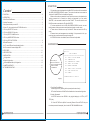
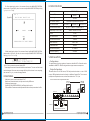
The currently in
Use PC is connected to
the Port 7 of SLAVE and this
SLAVE is cascaded
to the MASTER
MAIN MENU
───────────────────────
F1 AUTO. SCAN MODE
F2 SELECT PC
F3 SEARCH PC NAME
F4 EDIT PC NAME
F5 MORE SYSTEM
F6 EDIT UNIT/PC PSW.
F7 OSD POSITION
F8 HELP
PRESS ESC TO EXIT
Figure(1)
1. Front Panel Push Buttons
A.Selecting the PC by pressing the front panel push button directly.
B.The Auto Scan button of SLAVE will be disable when in cascade configuration.
2. Hot-key Commands
A. HOT-KEY can be set as <SCROLL > key (original design) or <L-CTRL> (LEFT
CTRL) key.
B. Press HOT-KEY twice (Within 3 seconds) (Remark: Press HOT-KEY only one
time when password is accepted), then into the HOT-KEY MAIN MENU mode.
1
4/8/16 PORT KVM SWITCH
自 動 多 電 腦 切 換 器
4/8/16 PORT KVM SWITCH
自 動 多 電 腦 切 換 器
2
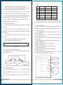
Table(1)
C. When on MAIN MENU screen, the OSD display is shown as Figure(1):
D. Line one shows PC:3+7 which indicates that the currently in use PC is connected
to the port 7 of SLAVE and this SLAVE is cascaded to the MASTER port 3.
E. Under this screen mode, user can press button<F1>, <F2>, <F3>, <F4>, <F5>,
<F6> for activating its function and can also press number key (0-9) to select PC.
F. While activating the HOT-KEY commands, MOUSE will be disable temporarily,
KEYBOARD can only control the OSD screen but CANNOT control the selected PC.
Sec
NUM LOCK
CAPS LOCK
5
OFF
OFF
SCROLL LOCK
ON
10
ON
OFF
OFF
15
ON
OFF
ON
20
OFF
ON
OFF
25
OFF
ON
ON
30
ON
ON
OFF
G. Press <ESC> to exit the MAIN MENU screen and return to the PC operation, the
F. Under AUTO SCAN mode, hitting<→> key is to select the nest powered-on PC.
G. Under AUTO SCAN mode, hitting<←> key is to select the previous powered-on
MOUSE and KEYBOARD can then work normally.
3. Using numerical key to select PC
PC.
A. Press the numerical key once and the screen sill show as Figure(2), then press 09 to select PC.
B. The port number which is connected to the MASTER should be input first and
following press <+> and then press the port number of the SLAVE which is connected to
the selected PC.
C. Hit <ENTER> to confirm. You can access the selected PC immediately if it is
powered on.
D. If the selected PC has not been powered on, OSD shows “DISABLE”.
E. If selected wrong PC number, OSD displays “ERROR”.
SELECT PC : ?
Figure(2)
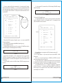
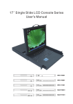
4. Press <F1> key to activate the AUTO SCAN function
A. In MAIN MENU, hitting <F1> key is to indicate to enter into AUTO SCAN function,
OSD will display as Figure(3).
AUTO SCAN
PC: 3+9
12345678
PC of MASTR
PC of SLAVE
4/8/16 PORT KVM SWITCH
自 動 多 電 腦 切 換 器
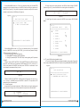
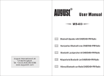
5. <F2> key SELECT PC function
A. Under MAIN MENU mode, hit <F2>key to enter the select PC function, the
screen displays as Figure(4).
B. Under the mode, use <↓ > or <↑ > key to move the cursor ☞ (CURSOR), use
<ENTER> to confirm the PC selection.
C. Only for 16 port model , you can use <Page Up> and <Page Down> key to display
more PC information.
D. Under OSD display: right side (STU) field shows the selected PC status:
+ :selected PC is POWER ON;
+ 4:selected PC is daisy-chained to 4 port model series which have
MASTER / SLAVE Configuration.
+ 8:selected PC is daisy-chained to 8 port model series which have
MASTER / SLAVE Configuration.
+16:selected PC is daisy-chained to 16 port model series which have
MASTER / SLAVE Configuration.
E. Line one shows PC: 3+7 which indicates that the selected PC is Port 7 of SLAVE
and this SLAVE is daisy-chained to MASTER port 3. (Figure(4))
PC:3+7
PORT SELECT MENU
STU
───────────────────────
1
PC1-1111
PC NAME
B. Under AUTO SCAN mode, the LED indicator of USER KEYBOARD flashes
according to different Scan Rate.
C. Under AUTO SCAN mode, hitting <-/_> or <-> key is to adjust down the SCAN
RATE.
D. Under AUTO SCAN mode, hitting <=/+> or <+> key is to adjust up the SCAN
RATE.
E. Table (1) shows the comparative list of LED light of Keyboard and the SCAN
RATE.
3
H. Exit Auto SCAN mode:
Press <ESC> key to exit the AUTO SCAN and return to the selected PC and also enter
into the MENU mode operation, and the MOUSE and KEYBOARD then work normally.
2
PC2-2222
3
SLAVER-3
4
PC4-4
5
PC5-5555
6
PC6
7
SLAVER-7
8
PC8
+
+8
+16
+4
PRESS ESC TO MAIN MENU
PC POWER OFF
PC POWER ON
PC side is
connected to
SLAVE of 4 / 8 / 1 6 p o r t
Figure(4)
4/8/16 PORT KVM SWITCH
自 動 多 電 腦 切 換 器
4
E. If cursor☞ selects the PC which is remarked with “⊕ò” means that the PC is daisychained to the SLAVE. Hit <ENTER> or <→> to enter into the cascaded SLAVE. OSD
shows the selected daisy-chained PC information (see Figure(5)). On the right side of
Line 1 of Figure(5) shows “SLAVER:??” to identity the on screen information is from??
Port of SALVER.
PC:3+7
SLAVER: 3
PORT SELECT MENU
STU
─────────
──────────────
1
S3-PC111
2
S3-PC222
3
EMAIL-1
4
SMPT-3
5
S3-PC555
6
S3-PC6
7
S3-PC7
8
S3-PC8
+
+
P resen t s t h e O S D
s creen i n f o r m ation
i s f rom S LAV E 3
PC:2
PORT NAME EDIT
STU
───────────────────────
1
PC1-1111
Figure(9)
E. Shown SLAVE PC information as Figure(5), press <←> to return to the MASTER
PC (shown as Figure(4)).
F. Press <ESC> key to come back to MAIN MENU (Shown Figure(1)).
6. <F3> key SEARCH PC function
A. On MAIN MENU screen mode, press <F3> to enter into PC NAME input mode to
search for the target PC, OSD message shown as FIGURE(6).
SEARCH
NAM E : ?
Figure(6)
B. Input at most 16 characters ( <A~Z>, numerical <0~9> and <-> etc) and press
<ENTER> as confirmation. For example: input <PC12345> and hit <ENTER> to start
searching the target PC <PC12345>. When targeted PC is found, it will switch to the PC
autocratically.
C. If no PC NAME is matched, the OSD will display “ERROR” message (shown as
Figure(7)).
ERROR
NAME : Pc12345
Figure(7)
4/8/16 PORT KVM SWITCH
自 動 多 電 腦 切 換 器
7. <F4> key EDIT PC NAME function
A. Under MAIN MENU mode: hit <F4> key to enter the edit PC name operation
(shown as Figure(9)), on the Line 1 of Figure(9) show PC : 2 indicating the current
screen information is from the second PC.
+
PRESS ESC TO MAIN MENU
5
D I SABLE
PC : 12 + 5 Pc 1 2 345
Figure(8)
+
SEARCH
D. If the searched PC is powered off, the OSD will display “DISABLE” message
(shown as Figure(8)).
2
PC2-2222
3
SLAVER-3
4
PC4-4
5
PC5-5555
6
PC6
7
SLAVER-7
8
PC8
+
+8
+
+8
PRESS ESC TO MAIN MENU
B. Under OSD mode: on the right side of (STU) field show the status of PC:
+ : PC is POWER ON;
+ 8: PC is daisy-chained to 8 port model series which have MASTER / SLAVE
Configuration.
C. use <↓> or <↑> key to move the cursor ☞(CURSOR), hit <ENTER> to enter the
edit PC name operation (shown as Figure(10)).
D. In Figure(10) the cursor☞ indicates to edit the name of PC2. the cursor becomes
the icon■ prompt to indicate the location you are editing. Input at most 16 characters
(<A~Z>, numerical <0~9> and <-> etc) and press <ENTER> as confirmation.
E. Edit SLAVE PC name: use <↓>, <↑>, <Page Up>, <Page Down> to select the PC
of SLAVE. Then press <→> to select the daisy-chained SLAVE PC, the OSD screen
shows as Figure (11): the right side of Line 1 shows “SLAVER:3” indicating the current
screen display is from ?? SLAVE.
4/8/16 PORT KVM SWITCH
自 動 多 電 腦 切 換 器
6
P C:2
PORT NAME EDIT
S TU
───────
─────────────── ─
1
PC1-1111
2
3
SLAVER-3
4
PC4-4
5
PC5-5555
6
PC6
7
SLAVER-7
8
PC8
+
+8
PC:3+7
MORE SYSTEM
───────────────────────
POWER ON SCAN
OFF
S C A N T I ME
5 SEC
HOT-KEY
SCROLL
BUZZER
ON
B A C K G R O U N DC O L O R
ON
+
+8
↓ ↑ FOR SELECT
? ? FOR SET
PRESS ESC TO MAIN MENU
P RESS ESC TO MAIN MENU
Figure (12)
Figure(10)
PC:2
SLAVER: 3
PORT NAME EDIT
STU
───────────────────────
1
S 3 -P C 1 1 1
2
S3-PC222
3
EMAIL-1
4
SMPT-3
5
S3-PC555
6
S3-PC6
7
S3-PC7
8
S3-PC8
+
+
+
+
PRESS ESC TO MAIN MENU
Figure(11)
F. Figure (11) shows the selected SLAVE PC information; hit <←> key to return to the
MASTER PC mode (shown as Figure(9)).
G. Hit <ESC> to back to the MAIN MENU mode (shown as Figure (1)).
8. <F5> key MORE SYSTEM function
A. Under MAIN MENU mode: hit <F5> key to enter the MASTER PC setting
operations. You can hit <↓ > or <↑ > or <← > or <→ > key to setup these
parameters.(shown as Figure (12))
B. Hit <↓> or <↑> key to move cursor and select item.
C. Hit <←> or <→> key to change the setting.
D. Hit <ESC> to go back to the MAIN MENU (Figure (1)) shown as follow:
7
4/8/16 PORT KVM SWITCH
自 動 多 電 腦 切 換 器
E. POWER ON SCAN setup:
a. OFF after resetting the MASTER PC, POWER ON SCAN will search and switch
to the PC which is power on directly.
b. ON After resetting MASTER PC, POWER ON SCAN will activate the AUTO
SCAN function, the operation step is same as above step 4.
F. SCAN TIME setup:
Same as {4-E}Table(1).
G. HOT-KEY setup:
Two choices - <SCROLL> and <L-CTRL>.
H. BUZZER setup:
a. OFF BUZZER is DISABLE while hitting HOT-KEY and front panel push button.
b. ON BUZZER is ENABLE while hitting HOT-KEY and front panel push button.
J. BACKGROUND COLOR setup:
a.OFF No background color
b. ON the background color is light -blue.
9. <F6> key EDIT UNIT/PC PSW
A. Password setting: MASTER Password and PC side Password.
a. MASTER Password: Controlling and Editing the MASTER password. When user
enters the HOT-KEY mode, hit <F6> to edit password. OSD will ask for the correct
password of MASTER (shown as Figure(13)). After entering the correct password, user
are allowed to use the device.
UNIT
PSW.:?
Figure (13)
b. PC Password: Controlling the operation of PC side. User will be asked for the
password, only when the password id entered correctly will the user be allowed to use
this PC. OSD screen shown as Figure (16).
4/8/16 PORT KVM SWITCH
自 動 多 電 腦 切 換 器
8
B . Under MAIN MENU mode: hit <F6> key for password editing and if the MASTER
password function has been already set, the OSD will ask for entering the password of
MASTER (as Figure(13)). Only when the password is entered correctly will the user be
allowed to use this device, OSD Shown as Figure(14).
Figure(14)
PC:2
EDIT UNIT OR PORT
───────────────────────
1 EDIT UNIT PSW.
2
B. When user enter the wrong password, the OSD will show message “ ERROR”
(Shown as Figure(17)). User will be asked for re-entering the correct password.
PC:
C. Under Figure (16) mode, user can hit HOT-KEY once to enter HOT-KEY MAIN
MENU.
PC:2
PORT PSW. EDIT
STU
───────────────────────
1
PSW1
PRESS ESC TO MAIN MENU
NEW
P SW.:?
Figure (15)
P c12345
Figure(17)
EDIT PC PORT PSW.
C. Under MAIN MENU mode: hit <F6> key for password editing. If the password
function of MASTER is not set yet (UNIT PSW.) ,you can deit new password directly
(OSD screen shown as Figure(14)).
D. Enter Editing function shown as Figure(14)
a. Editing MASTER password (EDIT UNIT PSW.)
b. Editing PC password (EDIT PC PORT PSW.) including editing the PC password
of SLAVE.
E. Select 1 means to EDIT UNIT PSW. : Editing MASTER password, OSD will show as
Figure(15), user should type 1-8 characters (valid characters are <A-Z>, <0-9> and <->)
as the new password of MASTER and then press <ENTER> as confirmation. User
should keep the new password firmly in mind.
ERROR
12 + 5
—
2
PSW2
3
PSW3
4
PSW-4
5
PSW-5555
6
PSW6
7
PSW7
8
PSW8
+
+8
+
+8
PRESS ESC TO MAIN MENU
Figure(18)
11. <F7> enter OSD position adjustable function
A. There are 2 kinds of OSD screen display adjustable, please refer to Figure(19).
One is to adjust MAIN OSD POSITION. The other is to adjust BANNER OSD POSITION.
Figure(19)
PC:2
OSD POSITION
───────────────────────
1 MAIN OSD POSITION
2 BANNER OSD POSITION
F. Select 2 to EDIT PC PORT PSW. : OSD will show as Figure(15). User can use <↓>
or <↑> to move ☞ (CURSOR) and press <ENTER> to select PC. The procedure of PC
password edition is same as step 6.
10. Enable Password:
A. If selected PC has setup the password. OSD will ask for entering the password of
the PC, (Shown as Figure (16)). Correct password is required to use the selected PC.
PC
P ASSWO R D
: ?
PC :
1 2+5
— PC12345
PRESS ESC TO MAIN MENU
Figure(16)
9
4/8/16 PORT KVM SWITCH
自 動 多 電 腦 切 換 器
4/8/16 PORT KVM SWITCH
自 動 多 電 腦 切 換 器
10
B. After selecting the choice 1, the screen will enter into MAIN OSD POSITION,
please refer to Figure(20).By then, the user can adjust MAIN OSD POSITION by hitting
<↓>/<↑>/<←>/<→> key.
PC:2
MAIN OSD POSITION
───────────────────────
UP
Figure(20)
IV.SPECIFICATION
Function
SPECIFICATION
MU41X
*Model (USB)
*Case design
19* Rack
*PC selection method
Push Button / Keyboard Hot Keys/ OSD
HD-15M × 4
*PC side connector
*Console side connector
LEFT
TO MOVE
RIGHT
HD-15M × 8
*Dimension(L × W × H .mm)
439mm × 189mm × 43. 5mm
DC12V
*PC side to Switch
10 meters
*Console side to Switch
5 meters
*Max. Resolution
1600 × 1200
*Video Bandwidth
200MHz
*Horizontal Frequency
C.When selecting the choice 2, the screen will enter into BANNER OSD POSITION,
please refer to Figure(21). By then, the user can adjust BANNER OSD POSITION by
hitting <↓>/<↑>/<←>/<→> key.
: T O
M O V E
P R E S S E S C T O M A I N M E N U
12. Hit <F8>key to enter the screen display HELP
This displays the contact information about the manufacturer. The user can find instant
technical support if the user met some usage difficulty. When the text is over one page,
the user can hit <↓>/<↑> to select the page needed.
III.FEATURES
A.Keyboard, mouse, monitor emulation & “PnP”.
B.Auto scan, Manual selection, Hot Key control and by OSD menu.
C. Keyboard, mouse reset.
D. With OSD (ON SCREEN DISPLAY) and Daisy chain function.
E. Reset Button: Reset mouse and keyboard simulation without power down the Pcs.
HD-15M × 16
HD-15F × 1 , MD-6F × 2, USB A Type x 2
*Power
DOWN
PRESS ESC TO MAIN MENU
MU161X
MU81X
30- 180KHz
*Vertical Frequency
43-250Hz
V.INSTALLATION
Configurations
For applications with a large number of computers, Auto Multi-PCs Controller can be
cascaded in a MASTER / SLAVE configuration to support even more computers.
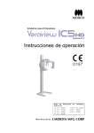
Single Configurations
Connects either a set of PS/2 mouse, PS/2 key board and monitor or a set of USB
mouse, USB keyboard and monitor directly to the Mater Console Port. Then connect
multiple sets of keyboard, mouse, and monitor cables to the "PC x" port.
Console & PCs side all of supported USB or PS/2
PC1
PC8
PC Side
PC Side
USB or PS/2
USB or PS/2
USB
USB
PS/2
PS/2
Master Unit
POWER
PROGRAM
DC 5V
PC1
PC2
PC3
PC4
PC5
PC6
PC7
PC8
Console side
USB Keyboard or PS/2 Keyboard
11
4/8/16 PORT KVM SWITCH
自 動 多 電 腦 切 換 器
4/8/16 PORT KVM SWITCH
自 動 多 電 腦 切 換 器
12
Cascade (Master/Slave) Configuration
You can connect a second level of one or more Auto Multi-PCs Controller to “PC1~PC6”
or “PC1~PC8” ports of a Master unit. Cascade configuration expands system ability
allowing you to select computers connected to the Master or Slaves. There is only one
Master, which has a mouse, a keyboard and a monitor connected to its CONSOLE port
directly operated by a user. Once connected, automatically configure themselves to
otherMaster or Slave. Slaves of different Auto Multi-PCs Controller can be mixed in
cascade configuration.
VI.TROUBLE SHOOTING:
The reason for not compatible with Auto Multi-PCs Controller
1. The BIOS in the mother board. (Basic Input / Output System)
2. The hardware equipment. (Keyboard, Mouse)
3. Software, OS (Operating System)
Situation
Solution
Mouse Hanged
* Check whether the mouse install mouse driver
* Exchange other mouse (USB mouse only for
user side)
* Connect the mouse to PC directly
* Exchange the PC port
* Try to select other port and then switch back
Master Unit
POWER
PROGRAM
DC 5V
PC2
PC1
PC3
PC4
PC5
PC7
PC6
PC8
PCs or next stage Units
PCs or next stage Units
Stage Unit
POWER
PROGRAM
PC1
DC 5V
PC2
PC3
PC5
PC4
PC7
PC6
PC8
Keyboard Hanged
PCs or next stage Units
* Exchange other Keyboard
* Connect the USB keyboard to PC directly
* Exchange the PC port
* Try to select other port and the switch back
PCs or next stage Units
Stage Unit
POWER
PROGRAM
DC 5V
PC1
PC2
PC3
PC4
PC5
PC6
PC7
PC8
PCs
Improper Operation
PCs
VI.LIMITED WARRANTY:
* Do not move keyboard, mouse or select PC
of the initial turn-on operation procedure is not
completed Adjust the dip switch
* Reboot after the PC is turned off for 5 seconds
later
* Try to select other port and then switch back
1.The product is freely repaired for 1 year since the buying date(according to the invoice
date). If any malfunction appears during daily use, please contact with our customer
department, and show your invoice when repairing.
2.The malfunctions caused by following reasons are not included in freely repairing
1)Parts damage caused by artificial reasons (where is visible physical damage)
2)Product's abnormal working caused by computer virus
3)Parts damage and malfunction which appears during customer's transportation
4)force majeure: abnormal working caused by earthquake, fire, accident(thieved, lost)
etc.
5)Product's abnormal working caused by self programmed software or third party
software.
6)Malfunction or damage caused by poor power environment or object entry inside.
7)Malfunction caused by self disassembly or repairing.
3.No charge is taken for Other equipments' malfunction which is directly or indirectly
caused by this product's malfunction.
13
4/8/16 PORT KVM SWITCH
自 動 多 電 腦 切 換 器
4/8/16 PORT KVM SWITCH
自 動 多 電 腦 切 換 器
14