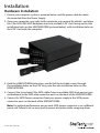
1
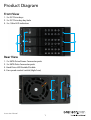
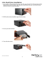
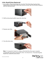
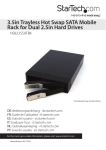
3 Drive Trayless 3.5” SATA/SAS Mobile Rack
HSB3SATSASBA
*actual product may vary from photos
DE: Bedienungsanleitung - de.startech.com
FR: Guide de l'utilisateur - fr.startech.com
ES: Guía del usuario - es.startech.com
IT: Guida per l'uso - it.startech.com
NL: Gebruiksaanwijzing - nl.startech.com
PT: Guia do usuário - pt.startech.com
For the most up-to-date information, please visit: www.startech.com
Manual Revision: 10/23/2013
FCC Compliance Statement
This equipment has been tested and found to comply with the limits for a Class B digital
device, pursuant to part 15 of the FCC Rules. These limits are designed to provide reasonable
protection against harmful interference in a residential installation. This equipment generates,
uses and can radiate radio frequency energy and, if not installed and used in accordance with
the instructions, may cause harmful interference to radio communications. However, there
is no guarantee that interference will not occur in a particular installation. If this equipment
does cause harmful interference to radio or television reception, which can be determined by
turning the equipment off and on, the user is encouraged to try to correct the interference by
one or more of the following measures:
• Reorient or relocate the receiving antenna.
• Increase the separation between the equipment and receiver.
• Connect the equipment into an outlet on a circuit different from that to which the receiver
is connected.
• Consult the dealer or an experienced radio/TV technician for help.
Use of Trademarks, Registered Trademarks, and other Protected Names and Symbols
This manual may make reference to trademarks, registered trademarks, and other
protected names and/or symbols of third-party companies not related in any way to
StarTech.com. Where they occur these references are for illustrative purposes only and do not
represent an endorsement of a product or service by StarTech.com, or an endorsement of the
product(s) to which this manual applies by the third-party company in question. Regardless
of any direct acknowledgement elsewhere in the body of this document, StarTech.com hereby
acknowledges that all trademarks, registered trademarks, service marks, and other protected
names and/or symbols contained in this manual and related documents are the property of
their respective holders.
Instruction Manual
Table of Contents
Product Diagram.....................................................................................1
Front View..................................................................................................................................................... 1
Rear View....................................................................................................................................................... 1
Introduction.............................................................................................2
Packaging Contents.................................................................................................................................. 2
System Requirements............................................................................................................................... 2
Installation...............................................................................................3
Hardware Installation............................................................................................................................... 3
3.5in Hard Drive Installation................................................................................................................... 4
3.5in Hard Drive Removal........................................................................................................................ 5
How to Use...............................................................................................6
Connecting the Hard Drive..................................................................................................................... 6
LED Indicator............................................................................................................................................... 6
Disconnecting the Hard Drive............................................................................................................... 6
Initializing the Hard Drive....................................................................................................................... 7
Technical Support...................................................................................8
Warranty Information.............................................................................8
Instruction Manual
i
Product Diagram
Front View
1. 3 x 2.5” Drive bays
2. 3 x 2.5” Drive bay key hole
3. 3 x /3.5in LED indicators
Rear View
1. 2 x SATA Drive Power Connector ports
2. 3 x SATA Data Connector ports
3. Hard Drive LED Enable/Disable
4. Fan speed control switch (High/Low)
Instruction Manual
1
Introduction
Packaging Contents
• 1 x 3 SATA HDD Backplane
• 3 x 18” SATA Cable
• 2 x Bay Key
• 1 x Installation Screw kit
• 1 x Instruction Manual
System Requirements
• 1X Computer System with SATA connectivity and two available 5.25” bays
• 2X Available SATA Power Connections
• Up to three 3.5” SATA/SAS Hard Drive(s)
WARNING! Hard drives and storage docks require careful handling, especially when
being transported. If you are not careful with your hard disk, lost data may result.
Always handle your hard drive and storage device with caution. Be sure that you
are properly grounded by wearing an anti-static strap when handling computer
components or discharge yourself of any static electricity build-up by touching a large
grounded metal surface (such as the computer case) for several seconds.
Instruction Manual
2
Installation
Hardware Installation
1. Ensure your computer system is powered down, and the power cable has been
disconnected from the Power Supply.
2. Open your computer case (refer to the computer user manual for details), and place
the 3.5in SATA/SAS HDD Backplane into two available 5.25” slots, lining up the side
installation holes on the HSB2535SATBK (pictured below), with installation holes on
the 5.25” slot inside the computer.
3. Hold the HSB3SATSASBA into place, and fix 8 of the included screws through
the installation holes on the 5.25” bays, into the side installation holes on the
HSB3SATSASBA.
4. Connect the 3x included 18in SATA cables from an available SATA host port on your
motherboard to the SATA data connector ports on the back of the HSB3SATSASBA.
5. Connect 2x SATA Power connectors from your power supply to the SATA power
connector ports on the back of the HSB3SATSASBA.
Note: For optimal performance, ensure each SATA power connector is on a different
power rail. Failure to do so may result in power disruption while swapping drives.
Instruction Manual
3
3.5in Hard Drive Installation
1. Insert either of the included bay keys into the your desired 3.5in Drive bay key holes
depending on which drawer you intend to install the drive into. And Turn the key
clockwise into the unlock position.
2. Pull the drive door handle to open the drive bay
3. Insert your desired drive
4. Close the drive door.
Instruction Manual
4
3.5in Hard Drive Removal
1. Insert either of the included bay keys into the “2.5in/3.5in Drive bay key holes
depending on which type of drive you intend to install. And Turn the key clockwise
into the unlock position.
2. Pull the drive door handle to open the drive bay
3. Remove your drive
4. Close the drive door.
Note: It is important to eject or unmount the hard drive from your computer
system before physically removing the drive. See How to Use - Disconnecting the
Hard Drive section for instructions.
Instruction Manual
5
How to Use
Connecting the Hard Drive
Once the drive has been installed in the drive bay, the drivers will install automatically,
and the inserted drive will be accessible as though it were installed within the system.
Note: some operating systems may require that the system be scanned for hardware
changes from within device manager, for the newly connected drive(s) to be
recognized.
Prior to using the drive, it will need to be formatted according to your operating
system requirements.
Refer to Initializing the Hard Drive.
LED Indicator
The HSB2535SATBK offers 3.5in LED indicators, to enable you to monitor drive activity.
The LED will flash while the hard drive is being accessed. Do not remove the enclosure
from the host computer while the LED is flashing, as it could damage the drive or the
enclosure, resulting in data loss.
Disconnecting the Hard Drive
Windows
The drive should be uninstalled from device manager, or unmounted using third party
hot swap software.
Note: Removing the connected drive while it is active in the system could result in
losing or corrupting data stored on the drive.
Mac OS X
To safely disconnect the attached drive from the host computer, close any windows
listing the contents of the removable drive. Once all windows are closed, click on the
icon for the drive on the desktop, and drag it to the Trash Can icon on the desktop.
Allow 5 seconds before physically removing the enclosure/drive from the computer.
Instruction Manual
6
Initializing the Hard Drive
1. If the SATA Hard Drive is blank it may need to be initialized and formatted before
use. From the main Windows desktop, right-click on “My Computer” (“Computer” in
Vista/ 7 / 8), then select Manage. In the new Computer Management window, select
Disk Management from the left window panel.
2. A dialog window should automatically appear, asking you to initialize the drive.
Depending on the version of Windows, it will give you the option of either creating
an “MBR” or “GPT” disk. GPT (GUID partition) is required for drives larger than 2TB but
is not compatible with some older operating systems, while MBR is supported by
newer and older operating systems.
3. Once initialized, locate the Disk that says it is “Unallocated” (check the listed hard
drive capacity to confirm it’s the correct hard drive) and then right-click in the
section that says “Unallocated” and select “New Partition”.
4. Several on screen prompts will follow walking you through the steps to create the
partition. Follow these prompts to complete partition creation.
Instruction Manual
7
Technical Support
StarTech.com’s lifetime technical support is an integral part of our commitment to
provide industry-leading solutions. If you ever need help with your product, visit
www.startech.com/support and access our comprehensive selection of online tools,
documentation, and downloads.
For the latest drivers/software, please visit www.startech.com/downloads
Warranty Information
This product is backed by a two year warranty.
In addition, StarTech.com warrants its products against defects in materials
and workmanship for the periods noted, following the initial date of purchase.
During this period, the products may be returned for repair, or replacement with
equivalent products at our discretion. The warranty covers parts and labor costs only.
StarTech.com does not warrant its products from defects or damages arising from
misuse, abuse, alteration, or normal wear and tear.
Limitation of Liability
In no event shall the liability of StarTech.com Ltd. and StarTech.com USA LLP (or their
officers, directors, employees or agents) for any damages (whether direct or indirect,
special, punitive, incidental, consequential, or otherwise), loss of profits, loss of business,
or any pecuniary loss, arising out of or related to the use of the product exceed the
actual price paid for the product. Some states do not allow the exclusion or limitation
of incidental or consequential damages. If such laws apply, the limitations or exclusions
contained in this statement may not apply to you.
Instruction Manual
8
Hard-to-find made easy. At StarTech.com, that isn’t a slogan. It’s a promise.
StarTech.com is your one-stop source for every connectivity part you need. From
the latest technology to legacy products — and all the parts that bridge the old and
new — we can help you find the parts that connect your solutions.
We make it easy to locate the parts, and we quickly deliver them wherever they need
to go. Just talk to one of our tech advisors or visit our website. You’ll be connected to
the products you need in no time.
Visit www.startech.com for complete information on all StarTech.com products and
to access exclusive resources and time-saving tools.
StarTech.com is an ISO 9001 Registered manufacturer of connectivity and technology
parts. StarTech.com was founded in 1985 and has operations in the United States,
Canada, the United Kingdom and Taiwan servicing a worldwide market.