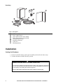
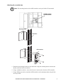
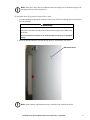
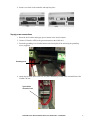
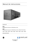
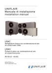
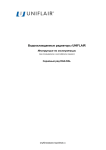
1
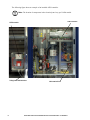
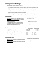
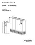
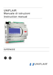
Automatic Floor Pressurization Sensor
for Uniflair CW — Installation
Overview
The Automatic Floor Pressurization Sensor (AFPS) detects a decrease in below-floor air pressure
caused by lifted floor tiles or airflow demand created by rack based cooling systems. By modulating
fan speed, an AFPS kit for your Uniflair Chilled Water (CW) Unit compensates for these changes in
air pressure.
The AFPS kit is supported by the following Uniflair CW models:
• TDCV0700
• TDCV1000
• TDCV1200
• TDCV1700
• TDCV2500
• TDCV3400
• TDCV4000
• TDCV4300
Safety Notices
DANGER
HAZARD OF ELECTRIC SHOCK, EXPLOSION, OR ARC FLASH
Turn off all power supplying this equipment before working on the equipment.
Failure to follow these instructions can result in death or serious injury.
WARNING
HAZARD FROM MOVING PARTS
Keep hands, clothing, and jewelry away from moving parts. Check the equipment for
foreign objects before closing the doors and starting the equipment.
Failure to follow these instructions can result in death, serious injury, or
equipment damage.
Inventory
na4083a
Item Description
AFPS controller
Power supply harness
Above-floor pressure sensor tubing
Below-floor pressure sensor tubing
Communication wiring
Installation hardware
tLAN card
Mounting bracket
Installation
Cooling Unit Shutdown
1. From the controller display, put the unit in stand-by and wait for the fans to stop.
2. Turn the disconnect switch to the OFF position.
DANGER
HAZARD OF ELECTRIC SHOCK, EXPLOSION, OR ARC FLASH
Turn off all power supplying this equipment before working on the equipment. All electrical
work must be performed by licensed electricians. Practice lockout/tagout procedures. Do
not wear jewelry when working with electrical equipment.
Failure to follow these instructions will result in death or serious injury.
2
Automatic Floor Pressurization Sensor for Uniflair CW — Installation
Attaching the controller box
Note: The mounting location of the AFPS controller varies per Uniflair CW unit model.
Installation location
for AFPS controller
Mounting bracket
Unit bracket
AFPS controller
1. Determine the mounting location on the unit bracket. Align the mounting bracket with the unit
bracket, and fasten with a screwdriver.
2. Using a standard screwdriver, remove the front cover and rear tabs from the AFPS controller.
3. Using a Phillips screwdriver, attach the AFPS controller to the mounting bracket using the four
screws provided.
Automatic Floor Pressurization Sensor for Uniflair CW — Installation
3
Installing the sensors
To install the below-floor sensor:
1. Locate the mounting point for the sensor head, and route the tubing through the bottom of the unit
and underneath the floor tiles to this location.
Note: Avoid placing the positive pressure sensor head under the raised floor where the
airflow velocity is high: for example, directly beneath the unit. The recommended
position for the pressure sensor head is 3–4 m (10–13 ft) away from the unit.
2. Fasten the mounting clamp to a raised floor post.
3. Ensure that excess tubing is carefully secured. Avoid sharp bends or kinks in the tubing.
Sensor head clamps on raised floor post
The above-floor pressure sensor can be installed in the port located at the bottom right corner of the
Uniflair unit.
To install the above-floor pressure sensor to the Uniflair port:
1. Using a standard screwdriver, pry off the cover on the sensor port.
2. Route the tubing through the cooling unit, neatly coiling any excess tubing.
3. From inside the unit, attach the sensor head to the port, then fasten the fitting into the port from
outside the unit.
4
Automatic Floor Pressurization Sensor for Uniflair CW — Installation
Note: If the unit is not in the air-conditioned room, the tubing can be installed using the wall
mounting bracket provided with the kit.
To mount the above-floor pressure sensor head to a wall:
1. After determining an appropriate location for the sensor, drill a hole through the wall and mount
the sensor bracket.
WARNING
HAZARD TO EQUIPMENT OR PERSONNEL
Verify that the area behind the wall is free of electrical wires or piping before drilling holes
into the wall.
Failure to follow these instructions can result in death, serious injury, or equipment
damage.
2. Route the tubing behind the wall and through the hole, then attach to the sensor.
Wall-mounted sensor
Note: Ensure that the wall-mounted sensor is installed away from direct airflow.
Automatic Floor Pressurization Sensor for Uniflair CW — Installation
5
tLAN connection
CAUTION
HAZARD TO EQUIPMENT
Circuit boards contained within this unit are sensitive to static electricity. Use one or more
electrostatic-discharge device while handling the boards.
Failure to follow these instructions can result in equipment damage.
1. Using a screwdriver, remove the Analog Selection cover on the controller inside the unit.
2. Cut or pry out the pre-cut plastic section (right-side) from the cover to access the tLAN card slot.
3. Aligning the connector pins, insert the tLAN card into the slot and push into place, making sure
the card is pushed all the way up against the two plastic supports on the UPC1 case.
CAUTION
HAZARD TO EQUIPMENT
Be sure all pins on the circuit board are properly seated and not bent or touching other
pins.
Failure to follow these instructions can result in equipment damage.
6
Automatic Floor Pressurization Sensor for Uniflair CW — Installation
4. Put the cover back on the controller and snap into place.
Supply power connections
1. Route the tLAN cables and supply power harness to the electrical panel.
2. Connect J3 from the AFPS to the green connector on the tLAN card.
3. Fasten the grounding wire from the harness to the back plate of the unit using the grounding
screw (supplied).
Grounding screw
4. Attach the electrical wires to the 24V AC power terminals provided in the terminal block of the
Uniflair CW unit.
Typical 24V AC
connection in unit
Automatic Floor Pressurization Sensor for Uniflair CW — Installation
7
The following figure shows an example of an installed AFPS controller.
Note: The location of components in the electrical panel vary per Uniflair model.
tLAN connection
AFPS controller
Tubing routed behind bracket
8
Main terminal block
Automatic Floor Pressurization Sensor for Uniflair CW — Installation
Configuration Settings
To configure the operating parameters of the unit:
1. Through the controller display, put the unit in stand-by mode and wait for the fans to stop.
2. From the main screen press the Prg key, select Service Menu and press Enter to confirm.
3. Type in the Service Password (see the envelope attached to the manual) and press Enter to
confirm.
4. Select Hardware Settings and press Enter to confirm.
5. Scroll through the screens by pressing the Down key until the screen for setting the parameters
appears.
Evaporating fan
Fan supply: fan power supply (Monophase/Triphase)
Modulation with air pressure enabled: fan modulation
activated by the air pressure transducer
Air pressure transducer:
Y = transducer and AFPS kit is installed in the unit
N = units in LAN network, when transducer is not
installed but fan modulation is activated
Transducer
EVAPORATING FAN
Fan Supply: 3ph
Modulation with Air
Pressure Enabled: Y
Air press.transducer Y/N
AIR PRESS: TRANSDUCER
Range Begin: the starting value of the transducer
Range End: end value of the transducer
Read Value: the reading taken by the sensor
Delta: maximum variation without activating the filter
Time: duration of the filter
Value: reading taken by the sensor
Range Begin.
Pa 000.0
Range End.
Read Value
Pa 100.0
Pa 020.0
Delta
Time
Value
INPUT FILTER
Pa
4.0
s
01
Pa
020.0
Evaporating fan speed
EVAPORATING FAN REGULAT.
Minimum speed: minimum evaporating fan speed during
modulation
Maximum speed: maximum evaporating fan speed during
modulation.
Minimum Speed: % 40
Maximum Speed: % 100
Automatic Floor Pressurization Sensor for Uniflair CW — Installation
9
Evaporating fan regulation
Setpoint: the reference pressure value that needs to be
maintained by the modulation of the fans
Dead Band: dead band regulation
Regul. Band: proportional regulation band
Integral Time: integral time
Derivat. Time: derivative time
Air pressure: the reading taken by the sensor
Evaporating Fan: evaporating fan regulation percentage
Alarm parameters
Setpoint
Dead Band
Regul. Band
Integral Time
Derivat.Time
Air Pressure
Pa
Pa
Pa
Pa
Evaporating Fan
020.0
000.0
160.0
s 040
s 000
020.0
% 000
EVAPORATING FAN REGUL.
Alarm Level: low air pressure alarm activation level
Alarm Delay: low air pressure alarm activation delay
time.
10
EVAPORATING FAN REGUL.
Alarm Level
Pa
015.0
Alarm Delay
s
060
Automatic Floor Pressurization Sensor for Uniflair CW — Installation
Configuration Settings with Units in a LAN
To configure fan speed modulation for several units connected through in a LAN, complete the following
steps:
1. From the main screen press the Prg key, select Settings Menu and press Enter to confirm.
2. Insert the Password Settings (see the envelope attached to the manual) and press Enter to
confirm.
3. Select LAN Settings and press Enter to confirm.
4. Scroll through the screens by pressing the Down key until the Parameters Setting screen appears.
5. After setting the parameters, press the Escape key several times until the main screen appears.
6. To save the data that has been entered, turn off the unit for several seconds, and then turn it back
on again.
7. Repeat steps 1–6 for each unit.
Note: Fan speed modulation settings can be determined through sensor reading of the unit, or
by calculating the average reading of all units in the LAN.
Air pressure control
Air Pressure Control:
Local Values: Fan speed modulation is controlled by the
pressure reading taken by the sensor on each unit.
LAN SETTINGS
Temp./Hum.
Mode:
Air Pressure Control
Mode:
Mean Values: Fan speed modulation is controlled by the
average pressure reading taken by the sensors on the
units connected in a local network.
Control
Local Values
Local Values
LAN SETTINGS
Temp./Hum.Control
Mode:
Local Values
Air Pressure Control
Mode:
Automatic Floor Pressurization Sensor for Uniflair CW — Installation
Mean Values
11
Customer support and warranty information is available at the APC Web site, www.apc.com.
© 2012 APC by Schneider Electric. APC, the APC logo, and Uniflair are owned by Schneider Electric
Industries S.A.S., American Power Conversion Corporation, or their affiliated companies. All other
trademarks are property of their respective owners.
990-5559
10/2012