1
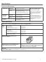
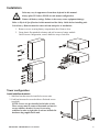
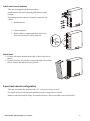
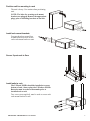
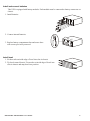
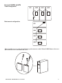
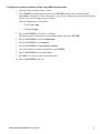
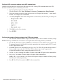
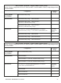
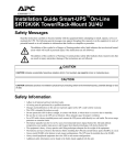
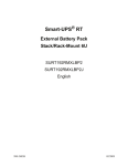
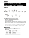
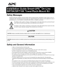
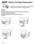
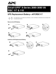
Smart-UPS® RC
External Battery Pack
Tower/Rack-Mount 4U
SRC96XLBP
SRC96XLBP2S
English
990-3486A
01/2009
Introduction
Overview
The American Power Conversion (APC®) SRC96XLBP external battery pack (XLBP) connects to an
APC Smart-UPS® RC. Together these units provide extended protection for electronic equipment (load)
from utility power blackouts, brownouts, sags and surges. The UPS and the XLBP together provide
continuous power from the batteries until utility power returns to safe levels or the batteries are fully
discharged.
Inventory
Read the Safety Guide before installing the unit.
Inspect the battery pack upon receipt. Notify the carrier and dealer if there is damage.
The packaging is recyclable; save it for reuse or dispose of it properly.
Check the battery pack package contents:
•
•
•
•
•
External Battery Pack (XLBP)
Front bezel
Stabilizer/rack-mount brackets
XLBP connector cable
Hardware supplied listed in table below
• Literature kit containing:
– Product documentation
– Smart-UPS® RC User Manuals CD
– Safety information
– Warranty information
NOTE: The model and serial numbers are located on a small, rear panel label. For some models, an
additional label is located on the chassis under the front bezel.
Hardware supplied
8
Rack-mount configuration:
Pan head screws for securing rack-mount brackets to unit
8
Rack-mount configuration:
Washers for securing rack-mount brackets to unit
2
Tower configuration:
Flat head screws for securing stabilizer brackets unit
Rack-mount configuration brackets
Tower configuration stabilizer brackets
su0211a
2
Accessories
Install accessories prior to connecting power to the UPS.
Refer to the APC Web site, www.apc.com for available accessories.
Optional accessories
• Additional external battery packs (XLBP)
• Additional battery strings
• 4-post rail kit
SRC96XLBP / SRC96XLBP2S User Manual
3
Specifications
Environmental Specifications
Temperature
Maximum
Elevation
Operating
0° to 40° C (32° to 104° F)
Storage
-15° to 30° C (5° to 86° F)
charge UPS battery every six months
30° to 70° C (86° to 158° F)
charge UPS battery every three months
Operating
3,000 m (10,000 ft)
Storage
15,000 m (50,000 ft)
Humidity
0 to 95% relative humidity,
non-condensing
This unit is intended for indoor use
only. Select a location sturdy
enough to handle the weight.
Do not operate unit where there is
excessive dust or temperature or
humidity are outside specified
limits.
Environmental factors impact
battery life. High temperatures, poor
utility power, and frequent, short
duration discharges will shorten
battery life.
Physical Specifications
Weight - Refer to Safety Guide supplied with this unit for lifting guidelines.
XLBP
model
SRC96XLBP2S
• without batteries
• with two 48 V battery modules
15 kg (32 lbs)
35 kg (76 lbs)
SRC96XLBP
• without batteries
• with six 48 V battery modules
15 kg (32 lbs)
75 kg (164 lbs)
each 48 V battery module
10 kg (22 lbs)
su0265a
Each 96 V battery string consists of two
48 V battery modules.
Maximum number of external battery packs
(XLBPs) supported by Smart-UPS RC
10
Combined weights of UPS and all XLBPs installed in a
rack must not exceed rack weight limits.
Dimensions
Length x Width x Height: 48 cm (19 in) x 43 cm (17 in) x 18 cm (7 in)
SRC96XLBP / SRC96XLBP2S User Manual
4
Installation
Units may vary in appearance from those depicted in this manual.
Always place UPS above XLBPs in rack-mount configuration.
Connect all battery strings. Failure to do so may cause equipment damage.
Refer to Physical Specifications in this manual and the Safety Guide before installing unit.
Unit is heavy. Batteries must be removed from unit prior to installation.
1. Remove screws securing battery compartment door. Remove door.
su0224a
su0223a
2. Grasp plastic flap attached to battery and pull to remove battery module.
Units in tower configuration, remove batteries at top of unit first.
Install stabilizer brackets
1. Stabilizer brackets must be installed on tower units.
2. Each bracket must be secured with two flat head screws
(supplied).
NOTE: Screws are pre-installed on left side of unit.
These screws must be removed from unit and used to
secure stabilizer bracket. Screws for securing
stabilizer bracket to right side of unit are included in
hardware bag supplied with unit.
SRC96XLBP / SRC96XLBP2S User Manual
su212a
Tower configuration
5
Install and connect batteries
This unit is equipped with battery modules.
Install batteries into unit beginning with batteries at the
bottom.
su0225a
Each string must be connected to battery connectors on
chassis.
1. Install batteries.
2. Connect batteries.
3. Replace battery compartment door and secure
door with screws previously removed.
x2
su0213a
x2
x2
su0216a
Install bezel
1. Fit three tabs on the bottom inside edge of bezel into slots in
chassis.
2. Tip bezel forward. Fit two tabs on top inside edge of bezel into
slots in chassis and snap bezel into position.
2-post rack-mount configuration
This unit is intended for installation in a 19”, two-post or four-post rack.
For details on 4-post rail and rack installation refer to instructions in rail kit.
Remove stabilizer brackets if they are installed. Remove four screws that secure each bracket.
SRC96XLBP / SRC96XLBP2S User Manual
6
Position unit for mounting in rack
The unit is heavy. Use caution when positioning
unit.
NOTE: The holes for securing rack-mount
brackets are plugged. Remove the appropriate
plugs prior to installing brackets on the unit.
su02
14a
x8
Install rack-mount brackets
Four pan head screws and four
washers must be used to secure
each rack-mount bracket to unit.
x4
s u 02
15a
x4
su0248a
Secure 2-post rack to floor
Install units in rack
The UPS and XLBPs should be installed at or near
bottom of rack. Always place the UPS above XLBPs.
Batteries must be removed from units prior to
installation in a rack.
su0217a
Two screws (not supplied), must be used to secure each
rack-mount bracket to rack.
SRC96XLBP / SRC96XLBP2S User Manual
7
Install and connect batteries
This UPS is equipped with battery modules. Each module must be connected to battery connectors on
chassis.
su0226a
1. Install batteries.
2. Connect internal batteries.
x2 x
2
su0218a
x2
3. Replace battery compartment door and secure door
with screws previously removed.
SRC96XLBP / SRC96XLBP2S User Manual
su0220a
Install bezel
1. Fit three tabs on inside edge of bezel into slots in chassis.
2. Tip bezel toward chassis. Fit two tabs on inside edge of bezel into
slots in chassis and snap bezel into position.
8
Connect XLBPs to UPS
UPS
XLBP
XLBP
XLBP
su221a
Tower configuration
Rack-mount configuration
UPS
XLBP
XLBP
su222a
XLBP
su264a
There is small cover over each external battery pack connector on the UPS and XLBP. Remove the screw
that secures the cover and remove the cover
SRC96XLBP / SRC96XLBP2S User Manual
9
Configure UPS parameters
This configuration affects the accuracy of the predicted runtime calculations the UPS performs
while running on battery power.
Refer to the Battery String Configuration tables at the end of this section for detailed instructions.
Smart-UPS RC models must be programed to recognize the number of battery strings connected to the UPS.
There are four options available for configuring the UPS to recognize the number of battery strings
1. PowerChute® Business Edition: Refer to the instructions included with the software
2. Network Management Card (NMC) Web interface: Refer to the instructions included with NMC
3. Network Management Card (NMC) terminal mode: Refer to the instructions below
4. UPS terminal mode
Configure UPS connection settings using NMC terminal mode
Connect the serial cable to the serial com port on rear side of UPS.
1. Open a terminal program, such as HyperTerminal®.
From the Desktop, go to: Start, Programs, Accessories, Communication, HyperTerminal
2. Follow the prompts to choose a name and select an icon. If the message, "...must install a
modem," click Cancel.
3. Go to File, Properties. Select the COM port that is connected to your UPS. The port settings are:
– bits per second - 2400
– data - bits 8
– parity - none
– stop bit - 1
– flow control - none
4. Click OK in each of two windows
5. Press ENTER to initiate connection to UPS.
SRC96XLBP / SRC96XLBP2S User Manual
10
Configure the number of battery strings using NMC terminal mode
1. Once the blank terminal window is open:
2. Press ENTER to initiate terminal mode. Press ENTER multiple times, until the prompt
User Name: is displayed. Follow the prompts. Type slowly, waiting until each character appears
on the screen prior to typing the next character.
Network Management Card defaults:
• User Name: apc
• Password: apc
3. Press 1 and ENTER to select Device Manager.
Select the model by entering the corresponding number, then press ENTER.
4. Press 3 and ENTER to select Configuration.
5. Press 1 and ENTER to select Battery.
6. Press 2 and ENTER to change Battery Settings.
7. Type in the number of battery strings then press ENTER.
8. Press 3 and ENTER to accept the changes.
9. Press ESC five times to return to the main menu.
10. Press 4 and ENTER to log out.
SRC96XLBP / SRC96XLBP2S User Manual
11
Configure UPS connection settings using UPS terminal mode
Connect the serial cable to the serial port on the back of the UPS. If using USB communication to the UPS,
disconnect USB cable prior to connecting serial cable.
1. Open a terminal program, such as HyperTerminal
From the Desktop, go to: Start, Programs, Accessories, Communication, HyperTerminal
2. Follow the prompts to choose a name and select an icon. Disregard the message, "...must install a
modem," if it is displayed. Click Cancel
3. Go to File, Properties. Select the COM port that is connected to your UPS. The port settings are:
– bits per second - 2400
– data - bits 8
– parity - none
– stop bit - 1
– flow control - none
4. Click OK in each of two windows
5. Press ENTER
Configure the number of battery strings using UPS terminal mode
1. Once the blank terminal window is open, follow these steps to enter the number of battery strings:
NOTE: Letter key commands are case sensitive. Use capital letters when using letter key commands.
2. Press Y. The UPS will respond with SM in the command box. If the UPS does not respond to the
Y command, ensure the serial cable is securely connected to the serial port on the UPS. Use only
an APC supplied serial cable.
3. When SM appears in the command box press the > key. The UPS will respond with the number of
battery strings connected to the UPS. If the UPS has not been previously programmed to
recognize the number of battery strings this number will be zero.
4. Use the + or - keys to change the number of battery strings. OK will appear in the command box.
5. Press > key. The number of battery strings will appear in the command box.
NOTE: The + or - keys and the > key must be used again to change the number of battery strings
from this point in the programming.
6. Press R. The UPS will respond with BYE in the command box.
SRC96XLBP / SRC96XLBP2S User Manual
12
Smart-UPS SRC XLI Models - Configure Number of Battery Strings
Each 96 V battery string consists of two 48 V battery modules. Count the number of battery strings being used and
enter that number.
Configuration
# of Battery
Strings
Factory Default
for all Models
UPS internal battery string
1
SRC96XLBP2S
UPS internal battery string + 1 SRC96XLBP2S
2
UPS internal battery string + 1 SRC96XLBP2S +
1 SRC004 (1 additional battery string)
3
UPS internal battery string + 1 SRC96XLBP2S +
2 SRC004 (2 additional battery strings)
4
The formula for configuring SRC96XLBP units is as follows:
UPS internal battery string + 3 x the number of SRC96XLBP units
# of battery
strings to be
entered
UPS internal battery string + 1 SRC96XLBP
4
UPS internal battery string + 2 SRC96XLBP units
7
UPS internal battery string + 3 SRC96XLBP units
10
SRC96XLBP
Smart-UPS SRC UXI Models - Configure Number of Battery Strings
Each 96 V battery string consists of two 48 V battery modules. Count the number of battery strings being used and
enter that number.
Configuration
# of Battery
Strings
Factory Default
for all Models
No UPS internal battery string
0
SRC96XLBP2S
1 SRC96XLBP2S
1
1 SRC96XLBP2S + 1 SRC004 (1 additional battery string)
2
1 SRC96XLBP2S + 2 SRC004 (2 additional battery strings)
3
The formula for configuring SRC96XLBP units is as follows:
3 x the number of SRC96XLBP units
# of battery
strings to be
entered
1 SRC96XLBP
3
2 SRC96XLBP units
6
3 SRC96XLBP units
9
SRC96XLBP
SRC96XLBP / SRC96XLBP2S User Manual
13
Contact Information
APC Worldwide Customer Support
Customer support for this or any other APC product is available at no charge in any of the following ways:
• Refer to the APC Web site to access documents in the APC Knowledge Base and to submit
customer support requests.
– www.apc.com (Corporate Headquarters)
Connect to localized APC Web sites for specific countries, each of which provides customer
support information.
– www.apc.com/support/
Global support searching APC Knowledge Base and using e-support.
• Contact an APC Customer Support center by telephone or e-mail.
Local, country-specific centers:
go to www.apc.com/support/contact for information.
Contact the APC representative or other distributor from whom you purchased your APC product for
information on how to obtain local customer support.
SRC96XLBP / SRC96XLBP2S User Manual
14
Maintenance, Transport, and Service
Replace battery modules
This UPS has easy-to-replace, hot-swappable battery modules. Replacement is a safe procedure, isolated
from electrical hazards. You may leave the UPS and connected equipment on during the replacement
procedure.
Once the batteries are disconnected the connected equipment is not protected from power outages.
Refer to the appropriate replacement battery user manual for battery module installation instructions. See
your dealer or contact APC at www.apc.com for information on replacement battery modules.
Be sure to deliver the spent battery(s) to a recycling facility or ship it to APC in the
replacement battery packing material.
Service
If the unit requires service do not return it to the dealer. Follow these steps:
1. Review the problems discussed in Troubleshooting in the UPS manual to eliminate common
problems.
2. If the problem persists, contact APC Customer Support through the
APC Web site, www.apc.com.
– Note the model number of the unit, the serial number located on the back of the unit, and the
date purchased. If you call APC Customer Support, a technician will ask you to describe the
problem and attempt to solve it over the phone. If this is not possible, the technician will issue
a Returned Material Authorization Number (RMA#).
– If the unit is under warranty, repairs are free.
– Procedures for servicing or returning products may vary internationally. Refer to the APC Web
site for country specific instructions.
3. Pack the unit in its original packaging. If this is not available:
– Pack the unit carefully to avoid damage in transit. Never use Styrofoam beads for packaging.
– Damage sustained in transit is not covered under warranty.
4. Always DISCONNECT THE UPS BATTERY before shipping in compliance with U.S.
Department of Transportation (DOT) and IATA regulations. The battery(s) may remain in the
unit.
5. Mark the RMA# on the outside of the package.
6. Return the unit by insured, prepaid carrier to the address given to you by Customer Support.
Entire contents copyright 2008 American Power Conversion Corporation. All rights reserved. Reproduction in whole or in part without
permission is prohibited.
APC, the APC logo, Smart-UPS and PowerChute are trademarks of American Power Conversion Corporation. All other trademarks, product
names, and corporate names are the property of their respective owners and are used for informational purposes only.
SRC96XLBP / SRC96XLBP2S User Manual
15
Two-Year Warranty
The limited warranty provided by American Power Conversion (APC®) in this statement of Limited Factory Warranty applies only to
products you purchase for your commercial or industrial use in the ordinary course of your business.
Terms of warranty
APC warrants its products to be free from defects in materials and workmanship for a period of two years from the date of purchase. The
obligation of APC under this warranty is limited to repairing or replacing, at its sole discretion, any such defective products. This warranty
does not apply to equipment that has been damaged by accident, negligence or misapplication or has been altered or modified in any way.
Repair or replacement of a defective product or part thereof does not extend the original warranty period. Any parts furnished under this
warranty may be new or factory-remanufactured.
Non-transferable warranty
This warranty extends only to the original purchaser who must have properly registered the product. The product may be registered at the
APC Web site, www.apc.com.
Exclusions
APC shall not be liable under the warranty if its testing and examination disclose that the alleged defect in the product does not exist or was
caused by end user or any third person misuse, negligence, improper installation or testing. Further, APC shall not be liable under the
warranty for unauthorized attempts to repair or modify wrong or inadequate electrical voltage or connection, inappropriate on-site operation
conditions, corrosive atmosphere, repair, installation, start-up by non-APC designated personnel, a change in location or operating use,
exposure to the elements, Acts of God, fire, theft, or installation contrary to APC recommendations or specifications or in any event if the
APC serial number has been altered, defaced, or removed, or any other cause beyond the range of the intended use.
THERE ARE NO WARRANTIES, EXPRESS OR IMPLIED, BY OPERATION OF LAW OR OTHERWISE, OF PRODUCTS SOLD,
SERVICED OR FURNISHED UNDER THIS AGREEMENT OR IN CONNECTION HEREWITH. APC DISCLAIMS ALL IMPLIED
WARRANTIES OF MERCHANTABILITY, SATISFACTION AND FITNESS FOR A PARTICULAR PURPOSE. APC EXPRESS
WARRANTIES WILL NOT BE ENLARGED, DIMINISHED, OR AFFECTED BY AND NO OBLIGATION OR LIABILITY WILL
ARISE OUT OF, APC RENDERING OF TECHNICAL OR OTHER ADVICE OR SERVICE IN CONNECTION WITH THE PRODUCTS.
THE FOREGOING WARRANTIES AND REMEDIES ARE EXCLUSIVE AND IN LIEU OF ALL OTHER WARRANTIES AND
REMEDIES. THE WARRANTIES SET FORTH ABOVE CONSTITUTE APC SOLE LIABILITY AND PURCHASER EXCLUSIVE
REMEDY FOR ANY BREACH OF SUCH WARRANTIES. APC WARRANTIES EXTEND ONLY TO PURCHASER AND ARE NOT
EXTENDED TO ANY THIRD PARTIES.
IN NO EVENT SHALL APC, ITS OFFICERS, DIRECTORS, AFFILIATES OR EMPLOYEES BE LIABLE FOR ANY FORM OF
INDIRECT, SPECIAL, CONSEQUENTIAL OR PUNITIVE DAMAGES, ARISING OUT OF THE USE, SERVICE OR INSTALLATION,
OF THE PRODUCTS, WHETHER SUCH DAMAGES ARISE IN CONTRACT OR TORT, IRRESPECTIVE OF FAULT, NEGLIGENCE
OR STRICT LIABILITY OR WHETHER APC HAS BEEN ADVISED IN ADVANCE OF THE POSSIBILITY OF SUCH DAMAGES.
SPECIFICALLY, APC IS NOT LIABLE FOR ANY COSTS, SUCH AS LOST PROFITS OR REVENUE, LOSS OF EQUIPMENT, LOSS
OF USE OF EQUIPMENT, LOSS OF SOFTWARE, LOSS OF DATA, COSTS OF SUBSTITUENTS, CLAIMS BY THIRD PARTIES, OR
OTHERWISE.
NO SALESMAN, EMPLOYEE OR AGENT OF APC IS AUTHORIZED TO ADD TO OR VARY THE TERMS OF THIS WARRANTY.
WARRANTY TERMS MAY BE MODIFIED, IF AT ALL, ONLY IN WRITING SIGNED BY AN APC OFFICER AND LEGAL
DEPARTMENT.
Warranty claims
Customers with warranty claims issues may access the APC customer support network through the Support page of the APC Web site,
www.apc.com. Select your country from the country selection pull-down menu. Open the Support tab at the top of the Web page to obtain
contact information for customer support in your region.
SRC96XLBP / SRC96XLBP2S User Manual
16