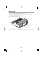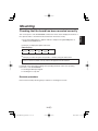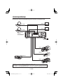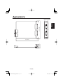
1
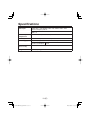
AV-HS04M3 Before operating this product, please read the instructions carefully and save this manual for future use. 01.AV-HS04M3_English.indd 1 日本語 РУССКИЙ ESPAÑOL ITALIANO FRANÇAIS Model No. ENGLISH DVI Input board DEUTSCH Operating Instructions 2007/10/01 18:32:30 ENGLISH VERSION Safety precautions CAUTION RISK OF ELECTRIC SHOCK DO NOT OPEN CAUTION: TO REDUCE THE RISK OF ELECTRIC SHOCK, DO NOT REMOVE COVER (OR BACK). NO USER SERVICEABLE PARTS INSIDE. REFER TO SERVICING TO QUALIFIED SERVICE PERSONNEL. The lightning flash with arrowhead symbol, within an equilateral triangle, is intended to alert the user to the presence of uninsulated “dangerous voltage” within the product’s enclosure that may be of sufficient magnitude to constitute a risk of electric shock to persons. The exclamation point within an equilateral triangle is intended to alert the user to the presence of important operating and maintenance (service) instructions in the literature accompanying the appliance. WARNING: • TO REDUCE THE RISK OF FIRE OR ELECTRIC SHOCK, DO NOT EXPOSE THIS APPARATUS TO RAIN OR MOISTURE. • THE APPARATUS SHALL NOT BE EXPOSED TO DRIPPING OR SPLASHING AND THAT NO OBJECTS FILLED WITH LIQUIDS, SUCH AS VASES, SHALL BE PLACED ON THE APPARATUS. CAUTION: TO REDUCE THE RISK OF FIRE OR SHOCK HAZARD AND ANNOYING INTERFERENCE, USE THE RECOMMENDED ACCESSORIES ONLY. CAUTION: TO REDUCE THE RISK OF FIRE OR SHOCK HAZARD, REFER CHANGES OF SWITCH SETTINGS INSIDE THE UNIT TO QUALIFIED SERVICE PERSONNEL. indicates safety information. 1 (E) 01.AV-HS04M3_English.indd Sec1:1 2007/10/01 18:32:37 For CANADA This class A digital apparatus complies with Canadian ICES-003. Cet appareil numérique de la classe A est conforme à la norme NMB-003 du Canada. FCC Note: This equipment has been tested and found to comply with the limits for a class A digital device, pursuant to Part 15 of the FCC Rules. These limits are designed to provide reasonable protection against harmful interference when the equipment is operated in a commercial environment. This equipment generates, uses, and can radiate radio frequency energy, and if not installed and used in accordance with the instruction manual, may cause harmful interference to radio communications. Operation of this equipment in a residential area is likely to cause harmful interference in which case the user will be required to correct the interference at his own expense. ENGLISH Safety precautions Warning: To assure continued FCC emission limit compliance, the user must use only shielded interface cables when connecting to external units. Also, any unauthorized changes or modifications to this equipment could void the user’s authority to operate it. indicates safety information. 2 (E) 01.AV-HS04M3_English.indd Sec1:2 2007/10/01 18:32:38 Safety precautions IMPORTANT SAFETY INSTRUCTIONS Read these operating instructions carefully before using the unit. Follow the safety instructions on the unit and the applicable safety instructions listed below. Keep these operating instructions handy for future reference. 10) Protect the power cord form being walked on or pinched particularly at plugs, convenience receptacles, and the point where they exit from the apparatus. 1) Read these instructions. 2) Keep these instructions. 3) Heed all warnings. 4) Follow all instructions. 5) Do not use this apparatus near water. 6) Clean only with dry cloth. 7) Do not block any ventilation openings. Install in accordance with the manufacturer's instructions. 8) Do not install near any heat sources such as radiators, heat registers, stoves, or other apparatus (including amplifiers) that produce heat. 9) Do not defeat the safety purpose of the polarized or grounding-type plug. A polarized plug has two blades with one wider than the other. A grounding-type plug has two blades and a third grounding prong. The wide blade or the third prong are provided for your safety. If the provided plug does not fit into your outlet, consult an electrician for replacement of the obsolete outlet. 11) Only use attachments/accessories specified by the manufacturer. 12) Use only with the cart, stand, tripod, bracket, or table specified by the manufacturer, or sold with the apparatus. When a cart is used, use caution when moving the cart/apparatus combination to avoid injury from tipover. 13) Unplug this apparatus during lightning storms or when unused for long periods of time. 14) Refer all servicing to qualified service personnel. Servicing is required when the apparatus has been damaged in any way, such as power-supply cord or plug is damaged, liquid has been spilled or objects have fallen into the apparatus, the apparatus has been exposed to rain or moisture, does not operate normally, or has been dropped. indicates safety information. 3 (E) 01.AV-HS04M3_English.indd Sec1:3 2007/10/01 18:32:38 Safety precautions This symbol on the products and/or accompanying documents means that used electrical and electronic products should not be mixed with general household waste. For proper treatment, recovery and recycling, please take these products to designated collection points, where they will be accepted on a free of charge basis. Alternatively, in some countries you may be able to return your products to your local retailer upon the purchase of an equivalent new product. Disposing of this product correctly will help to save valuable resources and prevent any potential negative effects on human health and the environment which could otherwise arise from inappropriate waste handling. Please contact your local authority for further details of your nearest designated collection point. Penalties may be applicable for incorrect disposal of this waste, in accordance with national legislation. ENGLISH Information on Disposal for Users of Waste Electrical & Electronic Equipment (private households) For business users in the European Union If you wish to discard electrical and electronic equipment, please contact your dealer or supplier for further information. Information on Disposal in other Countries outside the European Union This symbol is only valid in the European Union. If you wish to discard this product, please contact your local authorities or dealer and ask for the correct method of disposal. 4 (E) 01.AV-HS04M3_English.indd Sec1:4 2007/10/01 18:32:38 Contents Safety precautions ......................... Introduction ..................................... Accessory ....................................... Precautions for use ........................ Name of each part .......................... 1 5 5 6 7 Mounting ......................................... 8 Connections .................................. 11 Appearance ................................... 12 Specifications ............................... 13 Introduction When this board is installed in the AV-HS400N/E multi format line switcher, it enables two DVI-I input lines to be supported. Each of the two DVI-I input lines supports XGA, SXGA and WXGA (60 Hz) signals. Accessory Operating instructions .................. 1 5 (E) 01.AV-HS04M3_English.indd Sec1:5 2007/10/01 18:32:39 Precautions for use Handle carefully. Use the product in an ambient temperature of 32 °F to 104 °F (0 °C to 40 °C). Avoid using the product at a cold place below 32 °F (0 °C) or at a hot place above 104 °F (40 °C) because extremely low or high temperature will adversely affect the parts inside. ENGLISH Do not drop the product, or subject it to strong shock or vibration. Power off before connecting or disconnecting cables. Before plugging or unplugging the cables, be sure to switch power off. Avoid humidity and dust. Avoid using the product at a humid, dusty place because much humidity and dust will cause damage to the parts inside. When the product is to be discarded When the product is to be discarded at the end of its service life, ask a specialized contractor to dispose of it properly in order to protect the environment. 6 (E) 01.AV-HS04M3_English.indd Sec1:6 2007/10/01 18:32:39 Name of each part DVI INPUTS DVI-I DVI-I DVI-I input connectors [DVI INPUTS] When connected to the SLOT1 option input connector: INPUT5 When connected to the SLOT2 option input connector: INPUT7 DVI-I input connectors [DVI INPUTS] When connected to the SLOT1 option input connector: INPUT6 When connected to the SLOT2 option input connector: INPUT8 Setting switches SW1 1 2 3 4 O N 1 2 3 4 5 6 7 8 O N SW500 <Setting switch table> SW1 Switch no. 1 2 3 4 Reserved Reserved Reserved Reserved Off On Factory setting — — — — — — — — Off Off Off Off Use switches no. 1 to 4 at the “off” (factory setting) position. SW500 Switch no. 1 2 3 4 5 6 7 8 Reserved Reserved Reserved Reserved Reserved Reserved Reserved Reserved Off On Factory setting — — — — — — — — — — — — — — — — Off Off Off Off Off Off Off Off Use switches no. 1 to 8 at the “off” (factory setting) position. 7 (E) 01.AV-HS04M3_English.indd Sec1:7 2007/10/01 18:32:39 Mounting <Notes> Be sure to ask the store or dealer where you purchased the product for assistance with mounting and removal. Set to OFF and unplug the power connector before mounting and removal. Before handling this board, touch a metal part of the AV-HS400N/E to discharge the static electricity from the human body. An anti-static wrist strap is recommended for safety. Failures may be caused if you touch this board while you are still charged with static electricity. Keep the metal parts of this board free of contact with other metal parts. Be sure to mount the blank panel installed with the AV-HS400N/E, after removing this board. When installing or removing this board, take care not to hurt yourself on the edges and metal parts of the boards. ENGLISH Install this board in the multi-format live switcher AV-HS400N/E. Turn off the power of the AV-HS400N/E, and unplug the power cord. Loosen the two screws of SLOT1 or SLOT2 on the input side at the rear of the AVHS400N/E, and remove the blank panel. SLOT2 SLOT1 Blank panel Screw Screw 8 (E) 01.AV-HS04M3_English.indd Sec1:8 2007/10/01 18:32:39 Mounting Align the board with the guide rails, and insert it slowly. Insert it all the way in. Take care not to use force to insert the board because the connectors may be damaged in the process. Attach the board using the two screws. Screw Screw After connecting the necessary cables, plug in the power cord, and turn on the power. 9 (E) 01.AV-HS04M3_English.indd Sec1:9 2007/10/01 18:32:41 Mounting Turn on the power of the AV-HS400N/E, and use the menu used to display the statuses of the option boards to check that the board has been mounted correctly. Press the [FUNC] button to light its indicator, and press the [SYSTEM] button to display the SYSTEM menu. ENGLISH Checking that the board has been mounted correctly Turn [F1] to display the OptVer sub menu. <Menu display> OptVer 14/14 Select Board Version IN-SL1 DVI Turn [F2] to select the option slot (IN-SL1 or IN-SL2) using the Select item. If the board has been mounted correctly, “DVI” will appear at the Board item. If it has not been mounted correctly, “None” will appear at the Board item. For details on the input signal settings and operating methods, refer to the operating instructions of the AV-HS400N/E. 4-3. Setting the DVI input signals 5-2. Setting the crosspoints Removal procedure Remove this board by following the procedures for mounting it in reverse. 10 (E) 01.AV-HS04M3_English.indd Sec1:10 2007/10/01 18:32:42 Connections Connections when not implementing gen-lock (frame synchronizer ON) PC HD SDI DVI or VGA HD SDI monitor PC HD SDI DVI or VGA HD SDI monitor POWER UTIL OUTPUTS Multi-format live switcher AV-HS400N/E INPUTS SLOT2 UTIL6 UTIL5 SLOT1 UTIL4 UTIL3 8 6 PC OUTPUTS 7 5 SLOT2 SLOT1 DVI INPUTS DVI-I ON DVI-I OFF SLOT 2 SLOT 2 Y Pb Y Pb DVI-I Pr 㨪IN ANALOG OUTPUTS Y ANALOG INPUTS Y Pr Pb Pb Pr SLOT 1 SLOT 1 Y Pr Pb Pr SDI OUTPUTS SDI INPUTS PGM UTIL2 UTIL1 2 1 3 4 OUT IN OUT 2 IN OUT SIGNAL GND 1 IN OUT IN ETHERNET RS422 REF TALLY GPI Power cord HD SDI HD camera HD SDI HD SDI HD camera HD SDI VTR HD camera Make the connection with this board while the power is off. For details on connecting individual devices, refer to the respective operating instructions. For details on operating individual devices, refer to the respective operating instructions. 11 (E) 01.AV-HS04M3_English.indd Sec1:11 2007/10/01 18:32:42 Appearance ENGLISH DVI INPUTS DVI-I 5-2/16 (130) DVI-I Unit: Inch (mm) 1-1/16 (27) 6 (152.5) 12 (E) 01.AV-HS04M3_English.indd Sec1:12 2007/10/01 18:32:43 Specifications DVI-I input XGA 1024 × 768, WXGA 1280 × 768, SXGA 1280 × 1024 Vertical frequency: 60 Hz DVI-I ×2 Ambient operating 32 °F to 104 °F (0 °C to 40 °C) temperature Humidity 10 % to 90 % (no condensation) Power supply DC 12 V (supplied from the AV-HS400N/E) Power consumption ?? W Dimensions (W H D) 6˝ × 1-1/16˝ × 5-2/16˝ (152.5 × 27 × 130 mm) Weight 0.4 lbs. (0.2 kg) 13 (E) 01.AV-HS04M3_English.indd Sec1:13 2007/10/01 18:32:43 ENGLISH Memo 14 (E) 01.AV-HS04M3_English.indd Sec1:14 2007/10/01 18:32:44