1
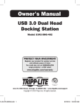
pr ch re R W
od an gis e
a
uc ce te gi rr
a
t— to r o s
ww w nlin tra nty
i
w. n a e ti
tri F tod on
pp R a :
lit EE y f
e. T or
co rip a
m p
/w Li
ar te
ra
nt
y
Owner’s Manual
DVI/USB + Audio Secure
KVM Switch
Models: B002-DUA2, B002-DUA4
Table of Contents
Package Contents
2
Optional Accessories
2
System Requirements
2
Features3
Safety Instructions
4
Stacking5
Grounding5
Installation6
Warranty & Warranty Registration
7
1111 W. 35th Street, Chicago, IL 60609 USA
www.tripplite.com/support
Copyright © 2011 Tripp Lite. All rights reserved.
1
201108190 93-3135.indd 1
8/30/2011 11:15:53 AM
Package Contents
• B002-DUA2 (2-Port) or B002-DUA4 (4-Port) Secure KVM Switch
• C13 to 5-15P Power Cord
• (4) Foot Pads
• Owner’s Manual
Optional Accessories
• P312-Series 3.5mm Stereo Audio Cables
• P556-006 DVI-A Male to HD15 Male Adapter Cable – 6 ft.
• P560-Series DVI-D Dual-Link Cables
• P560-xxx-A Series DVI-D Dual-Link + Audio Cables
• P561-Series DVI-D Single-Link Cables
• U022-Series USB 2.0 A/B Device Cables
System Requirements
• DVI or VGA* monitor
• USB mouse and keyboard
• Computer with a DVI or VGA* port
• Computer with a USB port
• Microphone with a 3.5mm Male connector (If using the microphone feature)
• Speakers with a 3.5mm Male connector (If using the speaker feature)
• Compatible with all major operating systems
*Requires a DVI to VGA adapter
2
201108190 93-3135.indd 2
8/30/2011 11:15:53 AM
Features
• National Information Assurance Partnership (NIAP) certified to EAL 2+.
• Safely switch between computers (up to 4) with varying security levels.
• Isolated Channels – Each port is its own channel, making it impossible for data to
be transferred between connected computers.
• Tamper-Warning Labels – Tamper-Warning labels will be placed on each side of the
KVM, providing visual evidence if the unit has been tampered with or compromised.
Removing these labels will void the warranty.
• Housing Intrusion Protection Technology – Housing Intrusion Protection
technology disables the KVM if the housing is opened, causing it to become
inoperable. When disabled, the front panel LEDs will flash repeatedly. Opening the
housing, and causing the unit to be disabled will void the warranty.
• Tamper-Proof Components – All internal circuitry is soldered directly to the board,
preventing the components from being tampered with.
• Fixed Firmware – Firmware is non-reprogrammable, securing against attempts to
alter the logic of the KVM.
• Automatic Keyboard Buffer Clearing – The keyboard buffer is automatically
cleared after data transmission, leaving no information stored in the switch.
• No Memory Buffer – The only way to access connected computers is via pushbutton.
Port switching methods such as On-Screen Display (OSD) and Hotkey Commands,
which require memory, have been excluded to further ensure data integrity.
• Compatible with all major operating systems.
• DVI-I Dual-Link signal supports digital video resolutions up to 2560 x 1600, and
analog video resolutions up to 2048 x 1536.
• Supports transfer of EDID information, allowing for optimal display performance.
• Audio support for both speaker and microphone.
3
201108190 93-3135.indd 3
8/30/2011 11:15:54 AM
Safety Instructions
• Read all of these instructions. Save them for future reference.
• Follow all warnings and instructions marked on the device.
• Do not place the device on any unstable surface (cart, stand, table, etc.). If the
device falls, serious damage will result.
• Do not use the device near water.
• Do not place the device near, or over, radiators or heat registers. The device cabinet
is provided with slots and openings to allow for adequate ventilation. To ensure
reliable operation, and to protect against overheating, these openings must never be
blocked or covered.
• The device should never be placed on a soft surface (bed, sofa, rug, etc.) as this will
block its ventilation openings. Likewise, the device should not be placed in a built-in
enclosure unless adequate ventilation has been provided.
• Never spill liquid of any kind on the device.
• Unplug the device from the wall outlet before cleaning. Do not use liquid or aerosol
cleaners. Use a damp cloth for cleaning.
• The device should be operated from the type of power source indicated on the
marking label. If you are not sure of the type of power available, consult your dealer
or local power company.
• Do not allow anything to rest on the power cord or cables. Route the power cord
and cables so that they cannot be stepped on or tripped over.
• If an extension cord is used with this device, make sure that the total ampere rating
of all products used on this cord does not exceed the extension cord ampere rating.
Make sure that the total rating of all products plugged into the wall outlet does not
exceed 15 amperes.
• Position system cables and power cables carefully; be sure that nothing rests on any
cables.
• To help protect your system from sudden transient increases and decreases in
electrical power, it is recommended that you plug your devices into a Tripp Lite
Surge Suppressor, Line Conditioner, or Uninterruptible Power Supply (UPS).
• When connecting or disconnecting power to hot-pluggable power supplies, observe
the following guidelines:
>Install the power supply before connecting the power cable to the power supply.
>Unplug the power cable before removing the power supply.
>If the system has multiple sources of power, disconnect power from the system
by unplugging all power cables from the power supplies.
• Never push objects of any kind into or through cabinet slots. They may touch
dangerous voltage points or short out parts, resulting in a risk of fire or electrical
shock.
• If the following conditions occur, unplug the device from the wall outlet and bring it
to qualified service personnel for repair.
>The power cord or plug has become damaged or frayed.
>Liquid has been spilled into the device.
>The device has been exposed to rain or water.
>The device has been dropped or the cabinet has been damaged.
>The device exhibits a distinct change in performance, indicating a need for service.
>The device does not operate normally when the operating instructions are followed.
4
201108190 93-3135.indd 4
8/30/2011 11:15:54 AM
Safety Instructions
continued
• Only adjust those controls that are covered in the operating instructions. Improper
adjustment of other controls may result in damage that will require extensive work
by a qualified technician to repair.
• This device is designed for IT power distribution systems with up to 230V phase-tophase voltage.
• To prevent damage to your installation, it is important that all devices are properly
grounded.
• This device is equipped with a three-wire grounding-type plug. This is a safety
feature. If you are unable to insert the plug into the outlet, contact an electrician
to replace your outlet with one that will accept this type of plug. Do not attempt
to defeat the purpose of the grounding-type plug. Always follow your local/national
wiring codes.
• Warning! There is a risk of explosion if the battery is replaced with an incorrect
battery type. Do not attempt to service the device yourself. Refer all servicing to
qualified service personnel.
Stacking
The KVM switch can be placed on any level surface that can safely support its weight
plus the weight of the attached cables. When placing the KVM switch on a desktop,
remove the backing material from the rubber feet that came with this packaging and
affix them to the switch’s bottom panel at the corners. Note: To ensure adequate
ventilation, allow at least 5 cm on each side and 13 cm at the back for power cord
and cable clearance.
Grounding
To prevent damage to your installation, it is important that all devices are properly
grounded. Use a grounding wire to connect the grounding terminal on the back of the
KVM to a suitably grounded object.
5
201108190 93-3135.indd 5
8/30/2011 11:15:54 AM
Installation
Note:
1. Before proceeding with installation, make sure that power to all devices being
connected to the KVM switch is turned off.
2. If you find that the keyboard and/or mouse has locked up, or the KVM switch is
acting erratically, pressing the Reset button on the front of the unit may resolve the
issue. Pressing this button performs the same function as powering the KVM switch
off and on.
3
1
2
6
4
1
Connect your monitor to the DVI console port on the back of the unit.
2
Connect your USB keyboard and mouse to the USB console ports on the back of
the unit.
3
Connect your speakers and microphone to the 3.5mm console ports on the back
or front of the unit. Note: The 3.5mm console ports on the front of the unit take
priority over those on the back.
4
Connect a computer to an available set of DVI, USB and Audio ports on the back of
the unit.
5
Repeat step 4 for each additional computer you are connecting.
6
Connect the included power cord to the KVM, and plug it into a Tripp Lite Surge
Suppressor, Power Distribution Unit (PDU), or Uninterruptible Power Supply (UPS).
Power on the unit.
7
Power on the connected computers. The Green LED will illuminate to indicate that a
powered-on computer is connected to the corresponding port. The Orange LED will
illuminate to indicate that the corresponding port has the focus of the KVM switch.
Note: By default, the lowest port is the one that is selected when the KVM is
powered on.
8
To switch ports, press the button on the front of the KVM that corresponds to the
port you wish to access.
6
201108190 93-3135.indd 6
8/30/2011 11:15:54 AM
Installation
continued
Specifications
B002-DUA2
B002-DUA4
Number of Computer Ports
2
4
Max Number of Connected
Computers
2
4
Console Ports
Computer Ports
LEDs
Maximum Supported Video
Resolution
DVI-I Female, (x2) USB A Female, (x2) 3.5mm Female
(x2) USB B Female, (x2) DVI-I (x4) USB B Female, (x4) DVI-I
Female, (x4) 3.5mm Female
Female, (x8) 3.5mm Female
(x2) Green / Online, (x2)
(x4) Green / Online, (x4)
Orange / Selected
Orange / Selected
Digital – 2560 x 1600, Analog – 2048 x 1536
100-240V, 50/60Hz, 0.5A
I/P Rating
Power Consumption
5.1W (120V), 5.1W (230V)
-20 to 60 C (-4 to 140 F)
Storage Temperature
0 to 80% RH, Non-Condensing
Humidity
1.75 x 13.25 x 6
Dimensions (H x W x D, In.)
Weight (lbs.)
6.1W (120V), 5.7W (230V)
0 to 40 C (32 to 104 F)
Operating Temperature
3.65
3.7
Warranty & Warranty Registration
1-YEAR LIMITED WARRANTY
Seller warrants this product, if used in accordance with all applicable instructions, to be free
from original defects in material and workmanship for a period of 2 years from the date of initial
purchase. If the product should prove defective in material or workmanship within that period,
Seller will repair or replace the product, in its sole discretion. Service under this Warranty can
only be obtained by your delivering or shipping the product (with all shipping or delivery charges
prepaid) to: Tripp Lite; 1111 W. 35th Street; Chicago IL 60609; USA. Seller will pay return
shipping charges. Visit www.tripplite.com/support before sending any equipment back for repair.
THIS WARRANTY DOES NOT APPLY TO NORMAL WEAR OR TO DAMAGE RESULTING FROM
ACCIDENT, MISUSE, ABUSE OR NEGLECT. SELLER MAKES NO EXPRESS WARRANTIES OTHER
THAN THE WARRANTY EXPRESSLY SET FORTH HEREIN. EXCEPT TO THE EXTENT PROHIBITED BY
APPLICABLE LAW, ALL IMPLIED WARRANTIES, INCLUDING ALL WARRANTIES OF MERCHANTABILITY
OR FITNESS, ARE LIMITED IN DURATION TO THE WARRANTY PERIOD SET FORTH ABOVE; AND
THIS WARRANTY EXPRESSLY EXCLUDES ALL INCIDENTAL AND CONSEQUENTIAL DAMAGES. (Some
states do not allow limitations on how long an implied warranty lasts, and some states do not
allow the exclusion or limitation of incidental or consequential damages, so the above limitations
or exclusions may not apply to you. This Warranty gives you specific legal rights, and you may have
other rights which vary from jurisdiction to jurisdiction).
Tripp Lite; 1111 W. 35th Street; Chicago IL 60609; USA
WARNING: The individual user should take care to determine prior to use whether this device is
suitable, adequate or safe for the use intended. Since individual applications are subject to great
variation, the manufacturer makes no representation or warranty as to the suitability or fitness of
these devices for any specific application.
7
201108190 93-3135.indd 7
8/30/2011 11:15:54 AM
Warranty & Warranty Registration
continued
WARRANTY REGISTRATION
Visit www.tripplite.com/warranty today to register the warranty for your new Tripp Lite product.
You’ll be automatically entered into a drawing for a chance to win a FREE Tripp Lite product!*
* No purchase necessary. Void where prohibited. Some restrictions apply. See website for details.
Warning
Use of this equipment in life support applications where failure of this equipment can reasonably
be expected to cause the failure of the life support equipment or to significantly affect its safety
or effectiveness is not recommended. Do not use this equipment in the presence of a flammable
anesthetic mixture with air, oxygen or nitrous oxide.
Regulatory Compliance Identification Numbers
For the purpose of regulatory compliance certifications and identification, your Tripp Lite product
has been assigned a unique series number. The series number can be found on the product
nameplate label, along with all required approval markings and information. When requesting
compliance information for this product, always refer to the series number. The series number
should not be confused with the marking name or model number of the product.
WEEE Compliance Information for Tripp Lite Customers and Recyclers
(European Union)
Under the Waste Electrical and Electronic Equipment (WEEE) Directive and implementing
regulations, when customers buy new electrical and electronic equipment from Tripp Lite
they are entitled to:
• Send old equipment for recycling on a one-for-one, like-for-like basis (this varies
depending on the country)
• Send the new equipment back for recycling when this ultimately becomes waste
FCC Information
This equipment has been tested and found to comply with the limits for a Class B digital
device, pursuant to Part 15 of the FCC Rules. These limits are designed to provide
reasonable protection against harmful interference in a residential installation. This
equipment generates, uses and can radiate radio frequency energy, and if not installed
and used in accordance with the instruction manual, may cause interference to radio
communications. However, there is no guarantee that interference will not occur in a
particular installation. If this equipment does cause harmful interference to radio or
television reception, which can be determined by turning the equipment off and on, the user
is encouraged to try to correct the interference by one or more of the following measures:
• Reorient or relocate the receiving antenna
• Increase the separation between the equipment and receiver
• Connect the equipment into an outlet on a circuit different from that which the
receiver is connected
• Consult the dealer or an experienced radio/television technician for help.
Tripp Lite follows a policy of continuous improvement. Product specifications are subject to
change without notice.
1111 W. 35th Street, Chicago, IL 60609 USA
www.tripplite.com/support
8
201108190 93-3135.indd 8
201108190 • 933135-EN
8/30/2011 11:15:54 AM