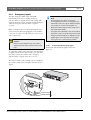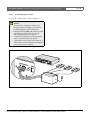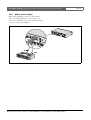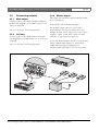
1
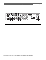
Plena Mixer Amplifier
Installation and User Instructions
en
PLE-1MA030-EU
PLE-1MA060-EU
PLE-1MA120-EU
Plena Mixer Amplifier | Installation and User Instructions
Important safeguards
Before installing or operating this product, always read
the Safety Instructions, which are available as a separate
document (9922 141 7014x). These instructions are
supplied together with all equipment that can be
connected to the mains.
Thank you for choosing a Bosch Security Systems
product!
Bosch Security Systems | 2007-11 | PLE-1MA030-EU, PLE-1MA060-EU, PLE-1MA120-EU en
en | 2
Plena Mixer Amplifier | Installation and User Instructions | Table of contents
en | 3
Table of contents
Important safeguards ...................................................................................................................................................2
Table of contents ...........................................................................................................................................................3
1. Introduction ....................................................................................................................................................................5
1.1 Purpose .....................................................................................................................................................................................5
1.2 Digital document .....................................................................................................................................................................5
1.3 Intended audience ..................................................................................................................................................................5
1.4 Related documentation ..........................................................................................................................................................5
1.5 Alerts ..........................................................................................................................................................................................5
1.6 Icons ...........................................................................................................................................................................................5
1.6.1 Note icons ...........................................................................................................................................................................5
1.6.2 Caution, Warning, and Danger icons ...........................................................................................................................5
1.7 Conversion tables ...................................................................................................................................................................6
2. Description .....................................................................................................................................................................7
2.1 The Plena product range .......................................................................................................................................................7
2.2 Contents of box .......................................................................................................................................................................7
2.3 The Plena Mixer Amplifier ......................................................................................................................................................7
2.4 Controls, connectors and indicators ..................................................................................................................................9
2.4.1 Front panel ..........................................................................................................................................................................9
2.4.2 Plena PLE-WP2Z3S wall panel .....................................................................................................................................9
2.4.3 Rear panel ........................................................................................................................................................................ 10
3. Installation ................................................................................................................................................................... 13
3.1 Unpack unit ............................................................................................................................................................................ 13
3.2 Install unit in rack (optional) ............................................................................................................................................... 13
3.3 Check settings/connections .............................................................................................................................................. 13
3.4 Connect unit to mains ......................................................................................................................................................... 13
4. Connections and settings ........................................................................................................................................ 15
4.1 Connecting inputs ................................................................................................................................................................ 15
4.1.1 Priority microphone (input 1) ....................................................................................................................................... 15
4.1.2 Secondary microphone (input 2) ................................................................................................................................ 16
4.1.3 Additional microphones (inputs 3 and 4) .................................................................................................................. 16
4.1.4 Emergency inputs ........................................................................................................................................................... 17
4.1.5 Music source inputs ....................................................................................................................................................... 19
4.2 Connecting outputs ............................................................................................................................................................. 20
4.2.1 Main output ...................................................................................................................................................................... 20
4.2.2 Call only ............................................................................................................................................................................ 20
4.2.3 Master output .................................................................................................................................................................. 20
4.2.4 Connecting speakers ..................................................................................................................................................... 21
4.3 Unit settings .......................................................................................................................................................................... 22
4.3.1 Rear panel settings ........................................................................................................................................................ 22
4.3.2 Pin settings and labelling .............................................................................................................................................. 24
Bosch Security Systems | 2007-11 | PLE-1MA030-EU, PLE-1MA060-EU, PLE-1MA120-EU en
Plena Mixer Amplifier | Installation and User Instructions | Table of contents
en | 4
5. Operation ..................................................................................................................................................................... 25
5.1 Switch on and off ................................................................................................................................................................. 25
5.1.1 Switch on ......................................................................................................................................................................... 25
5.1.2 Switch off ......................................................................................................................................................................... 25
5.2 Microphone/line controls .................................................................................................................................................... 26
5.3 Music controls ....................................................................................................................................................................... 26
5.3.1 Source selection ............................................................................................................................................................. 26
5.3.2 Volume control ................................................................................................................................................................ 26
5.4 Tone control .......................................................................................................................................................................... 26
5.5 Output controls ..................................................................................................................................................................... 26
5.5.1 Master volume control ................................................................................................................................................... 26
6. Technical data ............................................................................................................................................................. 27
6.1 Electrical ................................................................................................................................................................................. 27
6.1.1 Mains power supply ....................................................................................................................................................... 27
6.1.2 Power consumption ....................................................................................................................................................... 27
6.1.3 Performance .................................................................................................................................................................... 27
6.1.4 RJ-45 input 1 x ................................................................................................................................................................ 27
6.1.5 Mic/line input 4 x ............................................................................................................................................................. 27
6.1.6 Music inputs 3x ............................................................................................................................................................... 28
6.1.7 Emergency / telephone 1 x .......................................................................................................................................... 28
6.1.8 Master/music output 1 x ............................................................................................................................................... 28
6.1.9 Loudspeaker outputs 100 V ........................................................................................................................................ 28
6.1.10 Loudspeaker output 8 ohm* ........................................................................................................................................ 28
6.2 Mechanical ............................................................................................................................................................................. 28
6.3 Environmental ........................................................................................................................................................................ 28
Bosch Security Systems | 2007-11 | PLE-1MA030-EU, PLE-1MA060-EU, PLE-1MA120-EU en
Plena Mixer Amplifier | Installation and User Instructions | Introduction
1
Introduction
1.1
Purpose
The purpose of these Installation and User Instructions
is to provide information required for installing,
configuring and operating a Plena Mixer Amplifier.
1.2
1.6
Icons
1.6.1
Note icons
The icons used in combination with Notes provide extra
information about the Note. See the following
examples:
Digital document
Note
General icon for notes.
These Installation and User Instructions are also
available as a digital document in the Adobe Portable
Document Format (PDF).
1.3
Intended audience
Note
Consult the indicated source of information.
These Installation and User Instructions are intended
for installers and users of a Plena system.
1.4
Related documentation
Safety Instructions (9922 141 1036x).
1.5
Alerts
Four types of alerts are used in this manual. The alert
type is closely related to the effect that may be caused if
it is not observed. These alerts - from least severe effect
to most severe effect - are:
• Note
Alert containing additional information. Usually, not
observing a note alert does not result in damage to
the equipment or personal injuries.
• Caution
The equipment can be damaged if the alert is not
observed.
• Warning
Persons can be (severely) injured, or the equipment
can be seriously damaged, if the alert is not
observed.
• Danger
Not observing the alert can result in death.
en | 5
1.6.2
Caution, Warning, and Danger
icons
The icons used in combination with Caution, Warnings,
and Dangers indicate the type of hazard present. See the
following examples:
Caution, Warning, Danger
General icon for Cautions, Warnings and
Dangers.
Caution, Warning, Danger
Icon for risk of electric shock.
Caution, Warning, Danger
Icon for risk of electrostatic discharge.
Bosch Security Systems | 2007-11 | PLE-1MA030-EU, PLE-1MA060-EU, PLE-1MA120-EU en
Plena Mixer Amplifier | Installation and User Instructions | Introduction
1.7
Conversion tables
In this manual, SI units are used to express lengths,
masses, temperatures etc. These can be converted to
non-metric units using the following information.
table 1.1: Conversion of units of length
1 in =
25.4 mm
1 mm =
1 in =
2.54 cm
1 cm =
1 ft =
0.3048 m
1m=
1 mi =
1.609 km
1 km =
0.03937 in
0.3937 in
3.281 ft
0.622 mi
table 1.2: Conversion of units of mass
1 lb =
0.4536 kg
1 kg =
2,2046 lb
table 1.3: Conversion of units of pressure
1 psi =
68.95 hPa
1 hPa =
0.0145 psi
Note
1 hPa = 1 mbar.
9
°F = --- ( °C + 32 )
5
5
°C = --- ( °F – 32 )
9
Bosch Security Systems | 2007-11 | PLE-1MA030-EU, PLE-1MA060-EU, PLE-1MA120-EU en
en | 6
Plena Mixer Amplifier | Installation and User Instructions | Description
2
Description
2.1
The Plena product range
The Plena Mixer Amplifier is part of the Plena product
range. Plena provides public address solutions for places
where people gather to work, worship, trade, or relax. It
is a family of system elements that are combined to
create public address systems tailored for virtually any
application
The Plena product range includes:
• mixers
• preamplifiers
• power amplifiers
• a music source unit
• a digital message manager
• a feedback suppressor
• call stations
• an All-in-One system
• a voice alarm system
• a timer
• a charger
• a loop amplifier
The various elements are designed to complement each
other thanks to matched acoustical, electrical and
mechanical specifications.
2.2
Contents of box
The packaging box contains the following contents:
• PLE-1MA030-EU, PLE-1MA060-EU, or
PLE-1MA120
• Labels and colored pins for indicating favorite
settings
• Power cord
• Plena Bonus CD
• Mounting brackets (LBC 1901/00)
2.3
The Plena Mixer Amplifier
The Plena Mixer Amplifier is a high performance,
professional public address unit for mixing up to four
separate microphone/line signals, and any one of three
separate music signals. For a schematic overview of the
Plena Mixer Amplifier, see figure 2.1 on the next page.
en | 7
The volume of each microphone/line signal can be
individually adjusted to obtain the required mix; the
mixed output is controlled via the master volume
control and separate high/low tone controls.
The unit is easy to use, and provides a crisp call or clear
music. The amplifier also has enhanced features such as
ducking level control, priority, labelling, and setting
indicators.
All Microphone/line inputs can be switched between
microphone level and line level sensitivity. The inputs
are balanced but can also be used unbalanced. Phantom
power can be selected via a DIP switch to provide
power to condenser microphones. Input channels 1
and 2 can take priority over all other microphone and
music inputs:
• Input 1 can be activated by contact closure on a PTT
(push to talk). A chime can be configured to precede
an announcement.
• Input 2 can be switched automatically if a signal is
available at the input, for example, if someone
speaks into the microphone (VOX activation).
A telephone/100 V emergency input with VOX
activation is also provided for easy integration with
another PA system or a telephone paging system. It has
its own volume control and overrides all other inputs,
including the call station and inputs 1 and 2.
The unit also has a line output to add amplifiers for
larger systems that require more output power. This
output can be switched to music only, for example, so
that music on hold can be provided for the telephone
system.
Users can create custom labels for inputs and music
sources. These labels can be attached to the special
holders at the front of the mixer amplifier. Colored pins
can also be inserted at various positions around the
volume and tone dial controls to indicate favorite
settings for a particular application.
Bosch Security Systems | 2007-11 | PLE-1MA030-EU, PLE-1MA060-EU, PLE-1MA120-EU en
Plena Mixer Amplifier | Installation and User Instructions | Description
en | 8
An LED meter monitors the master output before the
zone selection. This signal is also present on the
headphone connector below the output meter. For
total reliability and ease of use, a limiter is integrated
into the output stage to restrict output if the user
applies too much signal.
100V
0
ducking
DIP drive
DIP
PTT
XLR+P h
0
LINE/MIC
Amplifier
Phantom
Power
100V
8 Ohm
Click
suppression
0
LINE/MIC
Music/Line Bal. output
LINE /MIC
LINE/MIC
1(disc)
2(radio)
LINE
201
3(aux)
Call Only
100V
115V,230V
figure 2.1: Schematic overview of the Plena Mixer Amplifier
Bosch Security Systems | 2007-11 | PLE-1MA030-EU, PLE-1MA060-EU, PLE-1MA120-EU en
0
8 Ohm
Plena Mixer Amplifier | Installation and User Instructions | Description
2.4
Controls, connectors and
indicators
2.4.1
Front panel
en | 9
Note
Users can create custom labels for the
microphone/line inputs and description of the
music sources. These labels can be attached to
the mixer amplifier at position numbers 2 and 3
(see figure 2.2). Colored pins can also be
inserted at various positions around the dial
controls to indicate the favorite settings for a
particular application. For more information on
inserting and removing pins, see section 4.3.2.
See figure 2.2 for an overview of the controls and
indicators.
1 Power button.
2 Label holder for user-defined description of
microphone/line inputs - custom labels can be
created by user.
3 Label holder for user-defined description of music
sources - custom labels can be created by user.
4 Master high tone control.
5 Master volume control - controls all inputs except
emergency and call station.
6 Output level meter (-18 db, 0 db)
7 Input level control:
• microphone/line 1
• microphone/line 2
• microphone/line 3
• microphone/line 4
8 Music source selector (for music inputs 1, 2, and 3).
9 Music source volume control.
10 Master low tone control.
11 Air inlet holes.
2.4.2
Plena PLE-WP2Z3S wall panel
The optional Plena PLE-WP2Z3S wall panel can be
used to remotely control the unit from a maximum of
four remote locations. The appearance of the wall panel
is matched to the Bosch loudspeaker volume controls.
The music source can be easily changed. The status of
each music source is indicated by an LED.
A standard CAT 5 cable is used to connect the wall
panel to the mixer-amplifier. The maximum distance is
200 m. Please refer to the relevant datasheet for more
information.
Note
Do not obstruct the airflow into the unit.
12 Headphone socket.
2
1
3
4
5
6
B
7
8
9
10
figure 2.2: Front panel
Bosch Security Systems | 2007-11 | PLE-1MA030-EU, PLE-1MA060-EU, PLE-1MA120-EU en
11
12
Plena Mixer Amplifier | Installation and User Instructions | Description
2.4.3
Rear panel
See figure 2.3 for an overview of the connectors and
switches:
1 Tel. emergency/100V input, Euro style pluggable
screw terminal connector - VOX function. This input
has highest priority.
2 Telephone emergency/100V input volume control control range -25 dB to 0dB (see number 1).
3 Remote control wall-panel-input, RJ-45 connector.
Wall panel incorporates: BGM source selection, and
zone on/off control.
4 Ducking level control for microphone/line inputs 1
and 2.
5 Music input (number 1 disc), 2x RCA/cinch
connectors. Stereo, summed mono.
6 Music input (number 2 radio), 2x RCA/cinch
connectors. Stereo, summed mono.
7 Music input (number 3 auxiliary), 2x RCA/cinch
connectors. Stereo, summed mono.
8 Music master output, XLR connector - switch setting
for line out, or music only. This output can carry out
either music only, or the master output. For more
information, see chapter 4.2.3.
9 Cooling fan (PLE-1MA120 only).
en | 10
14 Microphone/line 3 input, XLR connector - DIP
switch settings for mic/line, and phantom power (see
number 15).
15 DIP switch for microphone/line 3 and microphone/
line 4 (see numbers 14 and 16 respectively).
16 Microphone/line 4 input, XLR connector - DIP
switch settings for mic/line, and phantom power
(see number 15).
17 Outputs:
• Call only, screw terminal connector 100 V.
• Screw terminal connector 100 V, and 8 Ohm.
18 Mains fuse.
19 Earth connection screw.
Note
The unit must be earthed.
20 Mains connector (3-pole).
Note
Always allow adequate space at the rear of the
unit for ventilation.
10 Microphone/line 1 input with trigger, Euro style
pluggable screw terminal connector - DIP switch
settings for: chime, PTT (push to talk), mic/line,
speech filter, and phantom power (see number 12).
Input is wired in parallel with microphone/line 1,
XLR connector (see number 11).
11 Microphone/line 1 input, XLR connector - DIP
switch settings for: chime, PTT (push to talk), mic/
line, speech filter, and phantom power (see number
12). Input is wired in parallel with microphone/
line 1, Euro style pluggable screw terminal connector
(see number 10).
12 DIP switch for microphone/line 1 and microphone/
line 2 (see numbers 10 and 11, and 13 respectively).
13 Microphone/line 2 input, XLR connector - DIP
switch settings for speech filter, mic/line, VOX, and
phantom power (see number 12).
Bosch Security Systems | 2007-11 | PLE-1MA030-EU, PLE-1MA060-EU, PLE-1MA120-EU en
Plena Mixer Amplifier | Installation and User Instructions | Description
1
10
2
3
11
4
12
5
6
13
7
8
14
15
en | 11
9
16
17
figure 2.3: Rear panel
Bosch Security Systems | 2007-11 | PLE-1MA030-EU, PLE-1MA060-EU, PLE-1MA120-EU en
18 19 20
Plena Mixer Amplifier | Installation and User Instructions | Description
Intentionally left blank
Bosch Security Systems | 2007-11 | PLE-1MA030-EU, PLE-1MA060-EU, PLE-1MA120-EU en
en | 12
Plena Mixer Amplifier | Installation and User Instructions | Installation
3
3.1
Installation
3.3
Unpack unit
1 Connect any additional equipment (see section 4.1
and 4.2).
2 Check the settings (see section 4.3).
1 Remove the unit from the box, and discard the
packaging material according to local regulations.
2 Use your fingernails to carefully peel off the
protective plastic film from the label holders. Do not
use sharp or pointed objects.
3.2
en | 13
Install unit in rack (optional)
The Plena Mixer Amplifier is intended for tabletop use,
but you can also mount the unit in a 19" rack (see
figure 3.1).
If you mount the unit in a rack, you must:
• ensure that it does not exceed the overheating
temperature (45 °C ambient).
• use the included Bosch mounting brackets
(LBC 1901/00).
• remove the 4 feet from the bottom of the unit.
3.4
Check settings/connections
Connect unit to mains
Caution
Potential equipment damage. Before
connecting power, always check the voltage
indicator plate at the rear of the unit.
1 Make sure the power switch on the front of the unit
is set to Off.
2 Connect the power cord to the mains connector and
plug it into the mains outlet.
1
B
figure 3.1: Installing the unit in a rack
figure 3.2: Power connection and voltage selector
Bosch Security Systems | 2007-11 | PLE-1MA030-EU, PLE-1MA060-EU, PLE-1MA120-EU en
Plena Mixer Amplifier | Installation and User Instructions | Installation
Intentionally left blank
Bosch Security Systems | 2007-11 | PLE-1MA030-EU, PLE-1MA060-EU, PLE-1MA120-EU en
en | 14
Plena Mixer Amplifier | Installation and User Instructions | Connections and settings
4
Connections and settings
4.1
Connecting inputs
4.1.1
Priority microphone (input 1)
The priority microphone (or a generic call station) that
can be used with push to talk (PTT) should be
connected to “microphone/line 1 input”. The PTT
mode can be activated by setting the DIP switch (12) at
the rear of the unit. Microphone/line 1 input has
priority over all other microphone/line inputs.
Note
When connecting an unbalanced line level
(200 mV) signal to the microphone/line input,
connect it as follows: Signal to pin 2, pin 1 and
pin 3 to ground.
If, however, the “Tel. emergency/100V input” receives a
signal, all inputs including microphone/line 1 input will
be overruled.
The microphone/line 1 input has two connectors wired
in parallel:
• an XLR connector (for a 3 pole microphone), and
• a Euro style pluggable screw terminal connector.
en | 15
figure 4.1: XLR connector only
The Euro style pluggable screw terminal connector has
a trigger input, which can be used in combination with
the Euro and XLR connector.
The priority microphone can be connected to the
microphone/line 1 input as follows:
• XLR connector only. See figure 4.1.
• XLR connector with trigger. See figure 4.2.
• Euro connector with trigger. See figure 4.3.
• Euro connector only (without trigger).
figure 4.2: XLR connector with trigger
Note
If a microphone is connected to both the XLR
connector and the Euro connector for the
microphone/line 1 input, the input signals will be
added together.
Set the DIP switch settings next to the XLR connector
for microphone/line 1, as required. See section 4.3.
figure 4.3: Euro connector with trigger
Bosch Security Systems | 2007-11 | PLE-1MA030-EU, PLE-1MA060-EU, PLE-1MA120-EU en
Plena Mixer Amplifier | Installation and User Instructions | Connections and settings
4.1.2
Secondary microphone (input 2)
Connect a secondary microphone to “microphone/line
input 2”. See figure 4.4.
Microphone/line input 2 has a DIP switch (12) at the
rear of the unit for setting the VOX mode. If the DIP
switch is set to VOX, the microphone/line input will
automatically be switched when a signal is sensed at the
microphone/line 2 input. For example, when someone
speaks into the microphone, other sound will either be
muted or ducked, depending on the setting of the
ducking level control at the rear of the unit. See
section 4.3.
4.1.3
en | 16
Additional microphones
(inputs 3 and 4)
Connect additional microphones to microphone/line
inputs 3 and 5 as required. See figure 4.4. These
microphones will mix with the background music.
Set the DIP switch settings next to the XLR connector
for microphone/lines 3 and 4, as required. See
section 4.3.
The Tel. emergency/100V input and Microphone/line
input 1 all have priority over the Microphone/line
input 2. Therefore, any signal received on any one of
these inputs will always be heard regardless of the
ducking level control setting for Microphone/line
input 2.
Set the DIP switch settings next to the XLR connector
as required. See section 4.3.
figure 4.4: Connecting microphone inputs
Bosch Security Systems | 2007-11 | PLE-1MA030-EU, PLE-1MA060-EU, PLE-1MA120-EU en
Plena Mixer Amplifier | Installation and User Instructions | Connections and settings
4.1.4
en | 17
Emergency inputs
The Tel. emergency/100V input, with VOX
functionality, is used for receiving emergency
announcements or signals (such as a fire alarm). This
input has absolute priority, and will overrule all inputs
when an emergency announcement or signal is
received.
Either a telephone line or a 100 V input signal can be
connected to the Euro style pluggable screw terminal
connector (1) at the rear of the unit. See section 4.1.4.1
and section 4.1.4.2.
Caution
Never connect telephone lines and a 100 V
signal to the Euro style connector at the same
time.
Note
Tel. emergency input does not mute the
incoming signal so that an incoming pilot tone
will be fed to the zone outputs. With this feature
it is possible to use the mixer amplifier in a
Bosch Voice Alarm System when using end of
line boards (PLN-1EOL).
The signal that is delivered to the unit should be
quiet when a call is not made. The pilot tone and
frequencies below 300 Hz are filtered from the
trigger signal so that the input will not trigger
from a pilot tone or low frequency rumble.
4.1.4.1
Connecting 100 Volt input signal
Connect the 100 Volt input signal as shown in
figure 4.5.
To adjust the volume of the emergency announcement
or signal, turn the rotary dial (2) at the rear of the unit.
For safety reasons, the volume of the emergency
announcement or signal cannot be set to zero.
The master volume control setting (5) does not influence
the volume setting of the emergency announcement or
signal.
figure 4.5: Connecting 100 Volt input signal
Bosch Security Systems | 2007-11 | PLE-1MA030-EU, PLE-1MA060-EU, PLE-1MA120-EU en
Plena Mixer Amplifier | Installation and User Instructions | Connections and settings
4.1.4.2
Connecting telephone lines
Connect the telephone lines as shown in figure 4.6.
Caution
A connection to a telephone network must
always be made via a telephone coupler that
provides adequate isolation between the
telephone network (PBX) and the Plena system.
The telephone coupler must also meet all
relevant requirements for this type of
communication equipment as imposed by law
and/or responsible telecommunication
organizations in the country of use. Never try to
make a direct connection between the telephone
network and the mixer amplifier.
figure 4.6: Connecting emergency telephone lines
Bosch Security Systems | 2007-11 | PLE-1MA030-EU, PLE-1MA060-EU, PLE-1MA120-EU en
en | 18
Plena Mixer Amplifier | Installation and User Instructions | Connections and settings
4.1.5
Music source inputs
When using a CD player, tuner or other auxiliary
device for background music, connect the line-out
connectors of the music source to the appropriate line-in
connectors of the mixer amplifier.
figure 4.7: Connecting music source inputs
Bosch Security Systems | 2007-11 | PLE-1MA030-EU, PLE-1MA060-EU, PLE-1MA120-EU en
en | 19
Plena Mixer Amplifier | Installation and User Instructions | Connections and settings
en | 20
4.2
Connecting outputs
4.2.3
4.2.1
Main output
This output carries the master output of the mixer at line
level (1 V balanced).
Connect speakers to the 100 V or 8 Ohm terminal on
the Euro style pluggable screw terminal connector (17)
at the rear of the unit.
Also see section 4.2.4 “Connecting speakers”.
4.2.2
Call only
Connect speakers to the 100 V terminal on the Euro
style pluggable screw terminal connector (17) at the rear
of the unit.
Also see section 4.2.4 “Connecting speakers”.
Master output
To hear music only set the internal jumper.
Use the music output connector (8) to provide a
dedicated music out source for another device. For
example, the music master output can be connected to a
telephone coupler, so that callers can listen to music
when they are put on hold (see figure 4.8).
To select the dedicated music out source, set the internal
jumper. Only the music inputs (5, 6, and 7) will be
audible. All other inputs, including the Tel.
emergency/100V input will not be sent to this output.
figure 4.8: Connecting music source inputs
Bosch Security Systems | 2007-11 | PLE-1MA030-EU, PLE-1MA060-EU, PLE-1MA120-EU en
Plena Mixer Amplifier | Installation and User Instructions | Connections and settings
4.2.4
Connecting speakers
4.2.4.1
Constant voltage loudspeakers
4.2.4.2
en | 21
Low impedance loudspeakers
figure 4.10: Connecting speakers
figure 4.9: Connecting speakers
The mixer amplifier can drive 100 V constant voltage
loudspeakers.
Connect the loudspeakers in parallel and check the
loudspeaker polarity for in-phase connection. The
summed loudspeaker power should not exceed the
rated amplifier output power.
Connect low impedance loudspeakers to the 8 Ohm/0
terminals. This output can deliver the rated output
power into an 8 Ohm load. Connect multiple
loudspeakers in a series/parallel-arrangement to make
the combined impedance 8 Ohm or higher. Check the
loudspeaker polarity for in-phase connection.
You can use the Call Only output for 3-wire remote
volume control override. You can also use this output as
an extra zone where announcements can be heard, but
not music.
Bosch Security Systems | 2007-11 | PLE-1MA030-EU, PLE-1MA060-EU, PLE-1MA120-EU en
Plena Mixer Amplifier | Installation and User Instructions | Connections and settings
4.3
Unit settings
4.3.1
Rear panel settings
en | 22
The unit can be quickly set-up for operation by setting
the following controls at the rear of the unit:
• DIP switches
• Rotary dials.
See the following tables for an overview of the settings
and typical examples of their use.
table 4.1: DIP switch settings
DIP switch
On
Chime
Chime will be sounded at the
(mic/line 1)
beginning of an announcement.
PTT “Push to talk”
(mic/line 1 only)
Line
Speech filter
Phantom power
VOX
(mic/line 2 only)
This input is muted when the push
to talk contact is open. When the
push to talk contact is closed:
• this input is available for
speech.
• a chime will sound, if selected.
• the music and other mic/line
inputs will be reduced in
volume to the level set by the
ducking level control knob.
Input signal from line.
Enhances clarity of speech, by
cutting-off the lower frequencies
of the signal.
Provides power to condenser
microphones.
Temporarily suppresses the
background music to an
adjustable “ducking level” (see
table 4.2) while you speak into the
microphone. The VOX mode is
normally used with hand-held
microphones such as the
LBC 2900/15. Background music
and announcements will be heard
in the selected zones. A chime is
not available in this mode.
Off
Chime will not be sounded
at the beginning of an
announcement.
Push to talk off. The signal
will be mixed with the other
mic/line signals.
Microphone 1 will mix with
the background music or
the other microphones in
the selected zones.
Typical example (On)
Announcement of train
departure time.
Input signal from
microphone.
Speech filter inactive.
Depends on set-up.
Phantom power
unavailable.
Enable phantom power if
you use electret or
condenser microphones.
Use to make casual
announcements (such as
announcing the winner of
a competition) while
temporarily suppressing
the background music to
an adjustable ducking
level.
VOX inactive.
Microphone 2 will mix with
the background music or
the other microphones in
the selected zones.
Users can have private
conversations during live
broadcasts (for example,
with an all call callstation, such as the
PLE-1CS).
Use for announcements
Bosch Security Systems | 2007-11 | PLE-1MA030-EU, PLE-1MA060-EU, PLE-1MA120-EU en
Plena Mixer Amplifier | Installation and User Instructions | Connections and settings
table 4.2: Rotary controls
Rotary control
Effect
Ducking level control Sets the required ducking level when VOX and/or
push to talk is active (see table 4.1). When the
ducking level is set to mute, the music volume will be
fully attenuated; when the ducking level is set to mix,
both music and speech inputs can be heard - music
and speech will be mixed. When ducking the music
input is ducked (attenuated), the microphone/line
inputs are always muted when a call is made.
Telephone
Attenuates the emergency announcement or signal.
emergency/100V
Control range from -25 dB to 0 dB. For safety
volume control
reasons, the volume of the emergency
announcement or signal cannot be fully set to zero.
en | 23
Typical example
Set the ducking level control to
mute if you want the
announcement to be heard without
background music.
Set the volume of the emergency
announcement to a higher level
when the system is being used in
large open areas.
Note
When PTT or VOX are selected, the ducking
control controls between 3 dB attenuation (very
little ducking) to –∞ dB (muted).
When ducking, the music is also present on the
Call only output. If you do not want this, set the
ducking control to mute.
Bosch Security Systems | 2007-11 | PLE-1MA030-EU, PLE-1MA060-EU, PLE-1MA120-EU en
Plena Mixer Amplifier | Installation and User Instructions | Connections and settings
4.3.2
Pin settings and labelling
Users can create custom labels for the: microphone/line
inputs, description of the music sources, and audio
output zones 1 and 2. These labels can be attached to
the mixer amplifier at position numbers 2 and 3 (see
figure 2.2). Colored pins can also be inserted at various
positions around the dial controls to indicate the favorite
settings for a particular application.
The pins are engineered in such a way that they cannot
be taken out by hand. This is to prevent tampering. The
pins are intended to be inserted once, during installation
of the unit. The silver pins should be used to indicate
the preferred settings of the unit. The red pins can
optionally be used to indicate the maximum setting of a
knob.
If these settings have to be changed, use a pair of softtipped pliers to carefully remove the pins. If you do not
have a pair of soft-tipped pliers, you can use ordinary
pliers instead, but first place some plastic tape on the
tips of the pliers to prevent damaging the front of the
unit.
To remove the clear plastic covers in front of the labels:
1 Carefully insert a small screwdriver into the cut-out
at the bottom of the plastic cover.
2 Gently lift the cover, and bend it in the middle. Take
care not to force the cover or the front panel.
To reattach the plastic covers with paper labels:
1 Insert the paper label into the holder at the front of
the unit.
2 Pick up the cover, and then bend it slightly in the
middle by hand.
3 Fit the cover into the slot at the front of the unit, and
then gently release the cover, making sure that the
paper label stays in place.
Bosch Security Systems | 2007-11 | PLE-1MA030-EU, PLE-1MA060-EU, PLE-1MA120-EU en
en | 24
Plena Mixer Amplifier | Installation and User Instructions | Operation
5
Operation
5.1
Switch on and off
5.1.1
Switch on
en | 25
Caution
Potential equipment damage. Before applying
power, always check the voltage indicator plate
at the rear of the unit.
1 Set the power button (1) on the front of the unit to
On - pushed in (see figure 5.1).
5.1.2
Switch off
Set the power button (1) on the front of the unit to Off popped out (see figure 5.1).
2
1
3
4
5
6
B
7
8
9
10
figure 5.1: Front panel
Bosch Security Systems | 2007-11 | PLE-1MA030-EU, PLE-1MA060-EU, PLE-1MA120-EU en
11
12
Plena Mixer Amplifier | Installation and User Instructions | Operation
5.2
Microphone/line controls
Note
Users can create custom labels for the
microphone/line inputs and description of the
music sources. These labels can be attached to
the mixer amplifier at position numbers 2 and 3
(see figure 5.1). Colored pins can also be
inserted at various positions around the dial
controls to indicate the favorite settings for a
particular application.
en | 26
5.5
Output controls
5.5.1
Master volume control
Use the master volume control dial (5) to collectively
control the sound level of all outputs, except the
emergency announcement/signal.
Use the volume controls (7) to individually control the
sound level of microphone/line inputs 1 through 4.
5.3
Music controls
5.3.1
Source selection
Use the music source selector (8) to select one of the
connected music sources.
5.3.2
Volume control
Use the music source volume control (9) to control the
sound level of the selected music source.
5.4
Tone control
The tone controls are not standard bass and
treble controls: they can be used as a traditional tone
control with high and low control, but also have a
powerful contour that addresses problems found in real
situations.
The tone control for the low frequencies boosts deep
bass first without making the sound boomy, and cuts
rumble without loosing warmth in the low frequencies.
Use the Hi (high) and Lo (low) tone controls (see
figure 5.1, numbers 4 and 10) to change the tone.
Bosch Security Systems | 2007-11 | PLE-1MA030-EU, PLE-1MA060-EU, PLE-1MA120-EU en
Plena Mixer Amplifier | Installation and User Instructions | Technical data
6
Technical data
6.1
Electrical
6.1.1
Mains power supply
Voltage
230 VAC, ±10%, 50/60 Hz
Inrush Current PLE-1MA030-EU
4.5 A
Inrush Current PLE-1MA060-EU
5A
Inrush Current PLE-1MA120-EU
10 A
6.1.2
Power consumption
PLE-1MA030-EU
100 VA
PLE-1MA060-EU
200 VA
PLE-1MA120-EU
400 VA
6.1.3
Performance
Frequency response
50 Hz to 20 kHz (+1/-3 dB @ -10 dB ref. rated
output)
Distortion
<1% @ rated output power, 1 kHz
Bass Control
Max -12/+12 dB (frequency is level dependent)
Treble Control
Max -12/+12 dB (frequency is level dependent)
6.1.4
6.1.5
en | 27
Mic/line input 4 x
Input 1 (Push-to-talk contact with ducking
functionality)
5-pin Euro style, balanced, phantom
3-pin XLR, balanced, phantom
Input 2-4 (VOX with ducking functionality on input
2)
3-pin XLR, balanced, phantom
Sensitivity
1 mV (mic); 200 mV (line)
Vox sensitivity
-15 dB (attack time 20 ms; release time 4 s)
Impedance
>1 kohm (mic); >5 kohm (line)
S/N (flat at max volume)
63 dB (mic); >70 dB (line)
S/N (flat at min volume/muted)
>75 dB
Dynamic range
100 dB
S/N (flat at max volume)
>63 dB (mic); >70 dB (line)
S/N (flat at min volume/muted)
>75 dB
CMRR
>40 dB (50 Hz to 20 kHz)
Headroom
>25 dB
Speech filter
-3 dB @ 315 Hz, high-pass, 6 dB/oct
Phantom power supply
16 V via 1.2 kohm (mic)
RJ-45 input 1 x
Wall panel input
For PLE-WP3S2Z
Bosch Security Systems | 2007-11 | PLE-1MA030-EU, PLE-1MA060-EU, PLE-1MA120-EU en
Plena Mixer Amplifier | Installation and User Instructions | Technical data
6.1.6
Music inputs 3x
Connector
Cinch, stereo converted to mono
Sensitivity
200 mV
Impedance
22 kohm
S/N (flat at max volume)
>70 dB
S/N (flat at min volume/muted)
>75 dB
Headroom
>25 dB
6.1.10 Loudspeaker output 8 ohm*
Connector
Screw terminal, floating
PLE-1MA030-EU
16 V (30 W)
PLE-1MA060-EU
22 V (60 W)
PLE-1MA120-EU
31 V (120 W)
6.2
6.1.7
Emergency / telephone 1 x
Connector
7-pin, Euro style pluggable screw connector
Sensitivity tel
100 mV – 1 V adjustable
Sensitivity 100V
10 V – 100 V adjustable
Impedance
>10 kohm
S/N (flat at max volume)
>65 dB
VOX
threshold 50 mV; attack time 150 ms; release time 2 s
Master/music output 1 x
Connector
3-pin XLR, balanced
Nominal level
1V
Impedance
<100 ohm
6.1.9
Mechanical
Dimensions (H x W x D)
100 x 430 x 270 mm (19" wide, 2U high)
Mounting
Stand-alone, 19" rack
Color
Charcoal
Weight (PLE-1MA030-EU)
Approx. 5 kg
Weight (PLE-1MA060-EU)
Approx. 8.5 kg
Weight (PLE-1MA120-EU)
Approx. 10.5 kg
6.3
6.1.8
en | 28
Environmental
Operating temperature
-10 to +45 ºC
Storage temperature
-40 to +70 ºC
Relative humidity
<95%
Acoustic noise level of fan (PLE-1MA120-EU)
<33 dB SPL @ 1 m
Loudspeaker outputs 100 V
Connector
Screw connector, floating
Max / rated PLE-1MA030-EU
45 W / 30 W
Max / rated PLE-1MA060-EU
90 W / 60 W
Max / rated PLE-1MA120-EU
180 W / 120 W
Bosch Security Systems | 2007-11 | PLE-1MA030-EU, PLE-1MA060-EU, PLE-1MA120-EU en
For more information visit
www.boschsecuritysystems.com
© Bosch Security Systems B.V.
Data subject to change without notice
2007-11 | PLE-1MA030-EU, PLE-1MA060-EU, PLE-1MA120-EU en