1
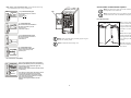
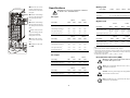
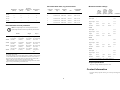
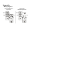
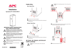
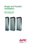
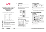
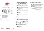
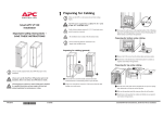
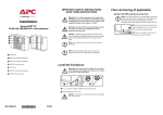
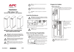
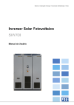
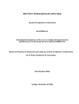
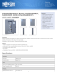
Note: Ensure that the unit is in its final location prior to installation. Installation MGE™ Galaxy™ 3500 10-30 kVA 208/220 V with batteries Prepare for Cables Bottom cable entry Note: Battery and utility power must not be connected until all other wiring has been completed. From the rear of the UPS, loosen the six M4 screws from the upper cover (the cable See Also: For parallel configurations see manual 9903568. landing area), and remove. Save the screws for later use. Level the Enclosure Warning: The system must be installed on a level floor. The leveling feet will stabilize the enclosure, but will not account for a badly sloped floor. Loosen the two M4 screws (one on each side) from the top part of the conduit box. Loosen the M4 screws attaching it to the bottom part (two screws in a 352 mm (13.8 in) enclosure), (three screws in a 523 mm (20.50 in) enclosure) and remove. Save the screws for later use. Loosen the four M4 screws (two on each side) from the conduit box bottom and remove. Save the screws for later use. Use a 13/14 mm wrench to adjust the four leveling feet. Punch as many holes as needed in the marked areas of the bottom conduit box. Ensure that the system is level. Caution: Do not move the enclosure after the leveling feet have been lowered. XR battery enclosure Mains Floor Anchoring (if applicable) Battery IMPORTANT SAFETY INSTRUCTIONS - SAVE THESE INSTRUCTIONS Output UPS Bypass UPS Attach the conduit box bottom to the enclosure Anchor the UPS enclosure to the floor Warning: ALL safety instructions in the Safety Sheet (990-2940) must be read, understood and followed when installing the UPS system. Failure to do so could result in equipment damage, serious injury, or death. Note: Floor-anchoring bolts are not provided with the UPS. Purchase the bolts locally (minimum size: M8). Follow the specifications given by the manufacturer of the floor anchoring system when bolting the UPS system to the floor. Warning: After the UPS has been electrically wired, do not start it up. Start-up is commissioned to authorized personnel from Schneider Electric. Caution: All electrical power and power control wiring must be installed by a qualified electrician, and must comply with local and national regulations for maximum power rating. 990-1957A-001 *990-1957A- 4/2009 Reuse the two transport brackets (one on each side) that were used to secure the UPS to the pallet during transport. Drill two to six holes in the floor for each bracket. Attach with bolts. (reuse the screws from step . Attach conduits to the conduit box. Run the cables through the conduits, the bottom of the conduit box, and up into the cable landing area. Attach the conduit box top to the conduit box bottom, and to the enclosure reusing the screws from step . Fasten the cables with cable ties. Connect the AC Input and AC Output Cables Dual mains Remove the three busbars A, Warning: Use compression type lugs ONLY. Do not loosen or add cables to any factory preinstalled cables on busbars. Use upper part of busbar for connection only. Connect the DC Battery Cables (if applicable) Connect battery cables BAT+, BAT–, and B, and C by removing two M6 screws from each busbar. N to the battery cable landings. Connect the AC input cables and Single mains Connect the AC input cables and the neutral to the input the neutral to the input cable landings. cable landings. Connect the AC output cables and the neutral to the output cable landings. beneath) using a screw. Connect the Communication Cables the neutral to the bypass cable landings. Connect the ground cables to the studs (earth symbol Connect the bypass cables and Connect the output cables and Warning: Make sure that the UPS is completely OFF as the connectors are very close to the power busbars. J106 and J108 pin connections Note: The UPS must be connected to either a dry contact or a 24 VDC EPO (Emergency Power Off) switch. the neutral to the output cable landings. Note: The external EPO +24 VDC, 1500 mA circuit can be supplied through other vendors. Connect the ground cables to Note: Always follow the pin connection procedures from the top and work down: J106 (8-1), J108 (1-6). the studs (earth symbol beneath) using a screw. J108 pin connections: 1 2 3 4 5 6 Normally open EPO Normally open EPO return Normally closed EPO Normally closed EPO return +24 V SELV supply SELV ground J106 pin connections: 2 8 7 6 5 4 3 2 1 Ext. charging control return External control of charging Q3 active return Q3 active Battery measurement supply* Battery unit quantity* Max. battery temperature* Battery measurement return* * Should be used with APC XR Enclosures Connect APC communication options EPO wiring – pin connections J108. Connect the EPO cable using one of the following four wiring configurations. 1: Dry Contacts Normally Open J108 EPO circuit XR battery enclosure J200 Note: The temperature sensor is provided in a plastic bag attached to the front of the UPS behind the front panel. EPO is activated when pin 1 is connected to pins 3 and 5. Connections: 2-4-6, 3-5 and 1 ( ) Front panel removal. BAT J108 +24 V EPO circuit 0V Note: The cable routing of the power chute software and the temperature sensor is identical. Use a coin or similar to turn the two black lock 2: +24 V Normally Open EPO is activated when an isolated SELV 24 VDC voltage is supplied on pin 1 with reference to pin 2. Connections: 3-5 and 4-6. BAT devices on either side of the display in the direction of each other to a vertical positon. Serial: Model: BATTERY UNIT Serial: Model: BATTERY UNIT 3: Dry Contacts Normally Closed J108 Push the front panel upwards and pull it outwards Serial: Model: BATTERY EPO is activated when a connection from pin 3 to pin 5 is opened. Connections: 4-6. UNIT Serial: Model: BATTERY Note: When connecting the Q3 auxiliary signal, use goldplated N/C auxiliary switch. UNIT Serial: Model: BATTERY UNIT Serial: Model: BATTERY Serial: Model: BATTERY UNIT Serial: Model: BATTERY EPO circuit Note: Reinstall the cable landing cover. +24 V EPO circuit EPO is activated when a SELV 24 VDC voltage is removed from pin 3 with reference to pin 4. 0V Pin connections J106 (UPS). J106 Charging control switch Q3 switch J200 (XR Batteries) UNIT to disengage the locking device at the top of the enclosure. Lift the front panel free of the two slots at the bottom of the enclosure. 4: +24 V Normally Closed J108 UNIT Pins 1 to 4 are for battery measurement (only applicable to MGE Galaxy 3500 XR Battery Enclosures (see J200 drawing). Pins 5 and 6 are for external maintenance bypass Q3 (auxiliary switch N/C type). When Q3 is closed, signals are fed back to the UPS controller (see Q3 drawing). Pins 7 and 8 are for external charge control. When 7 and 8 are closed, the UPS charges batteries with a pre-defined percentage (0-25-50-75-100%) of the maximum charging power. To be used in generator applications, or if special codes require control of charging. When Q3 is closed, signals are fed back to the UPS controller. 3 Remove the two screws from the cable-inlet at the Specifications Warning: The UPS must be supplied from a 208/120 V or 220/127 V 4W + GND 60 Hz source. front and remove the cableinlet plate. Network Management Guide the cable through card the hole in the bottom plate and up through the cableinlet. 15 kVA 208 V 220 V 208 V 220 V the cable upwards inside the panel. Input frequency (Hz) 40-70 40-70 40-70 40-70 Nominal input current (A)1 24.3 22.9 36.5 34.6 (A)2 26.7 25.2 40.2 38.0 Input current limit (A)3 32.8 32.8 49.5 49.5 inlet. 10 kVA UPS ratings Plug the cable into the probe socket / PowerChute Reattach the cable-inlet plate (). UPS ratings 10 kVA 15 kVA ± 192 20 kVA ± 192 30 kVA Nominal voltage (V) ± 192 ± 192 End voltage 1.6-1.75 V/cell (automatic, depending on load) AC input Guide the cable through the side panel hole and run Pull the cable out of the side panel through the hole closest to the Network Management Card area. Battery input Max. input current 20 kVA 208 V 220 V 208 V 220 V Input frequency (Hz) 40-70 40-70 40-70 40-70 Nominal input current (A)1 48.2 45.5 72.9 68.9 Max. input current (A)2 53.0 50.1 80.1 75.8 Input current limit (A)3 65.2 65.2 98.8 98.8 AC output 10 kVA 15 kVA UPS ratings 208 V 220 V 208 V 220 V Nominal output current (A) 27.8 26.2 41.6 39.4 20 kVA Nominal output current (A) 208 V 55.5 220 V 52.5 10 kVA 30 kVA 208 V 83.3 15 kVA UPS ratings 208 V 220 V 208 V 220 V Input frequency (Hz)4 50±10 or 60±10 50±10 or 60±10 50±10 or 60±10 50±10 or 60±10 26.2 41.6 39.4 Nominal input current (A)1 27.8 20 kVA 30 kVA UPS ratings UPS ratings Bypass input UPS ratings 208 V Input frequency (Hz)4 60±10 Nominal input current (A)1 55.5 30 kVA 220 V 208 V 220 V 60±10 60±10 60±10 52.5 83.3 78.7 Notes 1 Input current based on rated load and batteries fully charged. 2 Input current based on full battery recharge, nominal voltage and rated load. 3 Current limitation through electronic current limiting is based on full battery recharge and low input voltage. 4 Synchronization adjustable: +/–10Hz, +/–3Hz or +/–0.1Hz. Recommended cable sizes (AWG) Warning: At 100% switch mode load, the neutral must be rated for 200% phase current. Note: The recommended cable sizes are for a 30°C (86°F) temperature environment. 220 V 78.7 Caution: All wiring must comply with all applicable national and/or electrical codes. Note: Use Molex lug type or equivalent, and crimp to manufacturer’s specifications. 4 Recommended cable, lug and bolt sizes Mains input [AWG] AC output [AWG] DC input [AWG], 75ºC Wire Bypass input AWG 10 kVA 8 8 1 8 12 YA12CL2TC38 MD7-34R W12CVT 6 mm / 0.2 in 15 kVA 6 6 1 6 8 YA8CL2TC38 MD7-34R W8CVT 6 mm / 0.2 in 20 kVA 4 4 1 4 6 YA6CL2TC38 MD7-34R W6CVT 6 mm / 0.2 in 30 kVA 1 1 1 1 4 YA4CL2TC38 MD7-34R W4CVT 6 mm / 0.2 in 1 YA1CL2TC38 MD7-34R W1CVT 6 mm / 0.2 in Cable Size (AWG) Cable Lug Type Crimping Tool] Recommended current protection Single Any 3,4 Utility input Bypass input Utility input Output 10 kVA 35 A breaker (30 kAIC) 35 A breaker (30 kAIC) 35 A breaker (30 kAIC) 35 A fast-acting class J fuse 15 kVA 60 A breaker (30 kAIC) 60 A breaker (30 kAIC) 60 A breaker (30 kAIC) 60 A fast-acting class J fuse 20 kVA 80 A breaker (50 kAIC) 80 A breaker (50 kAIC) 80 A breaker (50 kAIC) 80 A fast-acting class J fuse 125 A breaker (63 kAIC) 125 A breaker (63 kAIC) 125 A breaker 125 A fast(63 kAIC) acting class J fuse 30 kVA Terminal Bolt Diameter 800% overload bypass operation 150% 125% overload overload normal/ normal/ battery battery operation operation Continuously 10 kVA Mains input –1 – – 34 A Bypass input 223 A – – 31 A Output 223 A 42 A 35 A 31 A Duration 500 ms 60 s 10 min. ∞ Mains input –1 – – 51 A Bypass input 333 A – – 46 A Output 333 A 63 A 52 A 46 A Duration 500 ms 60 s 10 min. Mains input –1 – – 68 A Bypass input 444 A – – 62 A Output 444 A 84 A 70 A 62 A Duration 500 ms 60 s 10 min. ∞ Mains input –1 – – 99 A Bypass input 667 A – – 92 A Output 667 A 125 A 105 A 92 A Duration 500 ms 60 s 10 min. ∞ 15 kVA Note: AC input/output over-current protection and AC input/output disconnect must be provided by the customer. Dual1,2 Die Minimum breaker settings ∞ 20 kVA 30 kVA 1 If the available fault current of the installation is below 30 kA, a lower kAICrated breaker can be used. 2 For breaker settings, refer to below table listing of available overload currents. 3 If the available fault current of the installation is less than 1200 A for the 10 kVA and 15 kVA UPS, and below 2300 A for the 20 kVA and 30 kVA UPS, a breaker (of the same value as for the bypass input) can be used. 4 Recommended maximum rating of a single-fuse configuration if the internal bypass is to be protected during a load short-circuit. 1 At single feed use the higher value of mains and bypass. Torque specifications The power wiring should be torqued to 7 Nm. Contact Information For local, country-specific centers: go to www.apc.com/support/ contact. 5 Appendix Wiring diagrams Diagram with Maintenance Bypass Panel Diagram without Maintenance Bypass Panel