1
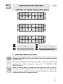
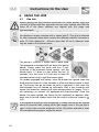
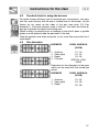
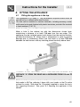
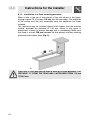
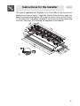
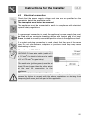
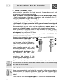
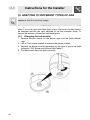
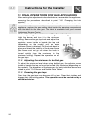
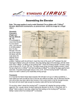
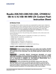
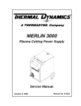
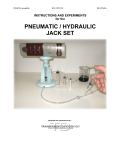
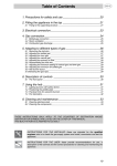
Table of Contents
1.
2.
3.
4.
5.
6.
7.
8.
9.
10.
11.
PRECAUTIONS FOR USE ................................................................... 22
DISPOSAL INSTRUCTIONS - OUR ENVIRONMENT POLICY ........... 22
SAFETY PRECAUTIONS ..................................................................... 24
GETTING TO KNOW YOUR APPLIANCE ........................................... 25
BEFORE INSTALLATION..................................................................... 25
USING THE HOB.................................................................................. 26
CLEANING AND MAINTENANCE ........................................................ 28
FITTING THE APPLIANCE................................................................... 29
GAS CONNECTION ............................................................................. 34
ADAPTING TO DIFFERENT TYPES OF GAS ..................................... 36
FINAL OPERATIONS FOR GAS APPLIANCES................................... 38
INSTRUCTIONS FOR THE USER: these provide recommendations for
use, a description of the controls and the correct procedures for cleaning
and maintaining the appliance
INSTRUCTIONS FOR THE INSTALLER: these are intended for the
qualified engineer who is to install, commission and test the appliance
21
Precautions for Use
1. PRECAUTIONS FOR USE
THIS MANUAL IS AN INTEGRAL PART OF THE APPLIANCE. TAKE GOOD CARE
OF IT AND KEEP IT TO HAND THROUGHOUT THE HOB'S LIFE CYCLE.
WE URGE YOU TO READ THIS MANUAL AND ALL THE INFORMATION IT
CONTAINS CAREFULLY BEFORE USING THE APPLIANCE.
INSTALLATION MUST BE CARRIED OUT BY QUALIFIED STAFF IN
COMPLIANCE WITH THE RELEVANT REGULATIONS. THIS APPLIANCE IS
INTENDED FOR HOUSEHOLD USE AND COMPLIES WITH THE EEC
DIRECTIVES CURRENTLY IN FORCE. THE APPLIANCE IS BUILT TO PROVIDE
THE FOLLOWING FUNCTION: COOKING AND HEATING FOODS; ALL OTHER
USES ARE TO BE CONSIDERED IMPROPER.
THE MANUFACTURER DECLINES ALL LIABILITY FOR USES OTHER THAN
THOSE STATED ABOVE.
NEVER USE THIS APPLIANCE FOR HEATING ROOMS.
NEVER USE PACKAGING RESIDUES UNATTENDED IN THE HOME.
SEPARATE THE VARIOUS WASTE PACKAGING MATERIALS BY TYPE AND
CONSIGN THEM TO THE NEAREST SEPARATE DISPOSAL CENTRE.
THIS APPLIANCE IS MARKED ACCORDING TO THE EUROPEAN DIRECTIVE
2002/96/EC ON WASTE ELECTRICAL AND ELECTRONIC EQUIPMENT (WEEE).
THIS GUIDELINE IS THE FRAME OF A EUROPEAN-WIDE VALIDITY OF
RETURN AND RECYCLING ON WASTE ELECTRICAL AND ELECTRONIC
EQUIPMENT.
NEVER OBSTRUCT THE OPENINGS
VENTILATION AND HEAT DISPERSAL.
AND
SLITS
PROVIDED
FOR
THE NAMEPLATE WITH THE TECHNICAL DATA, SERIAL NUMBER AND MARK
ARE IN A VISIBLE POSITION UNDERNEATH THE CASING.
THE NAMEPLATE MUST NEVER BE REMOVED.
22
Disposal instructions
2. DISPOSAL
INSTRUCTIONS
ENVIRONMENT POLICY
-
OUR
Our products are only packaged using non-pollutant, environment-friendly,
recyclable materials. We urge you to cooperate by disposing of the
packaging properly. Contact your local dealer or the competent local
organisations for the addresses of collection, recycling and disposal
facilities.
Never leave all or part of the packaging lying around. Packaging parts, and
especially plastic bags, may represent a suffocation hazard for children.
Your old appliance must also be disposed of properly.
Important: deliver the appliance to your local organisation authorised to
collect scrapped appliances. Proper disposal allows the intelligent
recovery of valuable materials.
Cut the power supply lead and remove it and the plug.
23
Safety Precautions
3. SAFETY PRECAUTIONS
SEE INSTALLATION INSTRUCTIONS FOR SAFETY REGULATIONS FOR
ELECTRIC OR GAS APPLIANCES AND FOR VENTILATION FUNCTIONS.
IN YOUR INTEREST AND TO ENSURE YOUR SAFETY, BY LAW ALL ELECTRIC
APPLIANCES MUST ONLY BE INSTALLED AND SERVICED BY QUALIFIED
STAFF, IN ACCORDANCE WITH THE RELEVANT REGULATIONS.
OUR APPROVED INSTALLATION ENGINEERS GUARANTEE YOU A JOB WELL
DONE.
GAS OR ELECTRIC APPLIANCES MUST ALWAYS BE DISCONNECTED BY
SUITABLY SKILLED PEOPLE.
THE PLUG TO BE CONNECTED TO THE POWER SUPPLY LEAD AND THE
RELATIVE SOCKET MUST BE OF THE SAME TYPE AND COMPLY WITH THE
RELEVANT REGULATIONS.
THE POWER SUPPLY SOCKET MUST BE ACCESSIBLE EVEN AFTER THE
APPLIANCE HAS BEEN BUILT-IN.
NEVER DISCONNECT THE PLUG BY PULLING ON THE POWER SUPPLY
LEAD.
THE APPLIANCE MUST BE CONNECTED TO EARTH IN COMPLIANCE WITH
ELECTRICAL SYSTEM SAFETY REGULATIONS.
IMMEDIATELY AFTER INSTALLATION, CARRY OUT A QUICK TEST ON THE
APPLIANCE FOLLOWING THE INSTRUCTIONS PROVIDED LATER IN THIS
MANUAL. IF THE APPLIANCE FAILS TO OPERATE, DISCONNECT IT FROM
THE ELECTRICAL MAINS AND CONTACT YOUR NEAREST SERVICE CENTRE.
NEVER ATTEMPT TO REPAIR THE APPLIANCE.
THE APPLIANCE BECOMES VERY HOT DURING USE. OVEN GLOVES
SHOULD ALWAYS BE WORN.
THE APPLIANCE IS INTENDED FOR USE BY ADULTS. KEEP CHILDREN AT A
SAFE DISTANCE AND NEVER ALLOW THEM TO PLAY WITH IT.
AFTER EACH USE, ALWAYS CHECK THAT THE CONTROL KNOBS ARE
TURNED TO 0 (OFF).
The manufacturer declines all responsibility for injury or damage caused
by failure to comply with the above regulations or deriving from tampering
with even just one part of the appliance and the use of non-original spare
parts.
24
Instructions for the User
4. GETTING TO KNOW YOUR APPLIANCE
Auxiliary Burner (AUX)
Rapid Burner (R)
Semi-rapid (SR) burner
Ultrarapid Burner (UR3)
Raised spoke pan stand
5. BEFORE INSTALLATION
Never leave packaging residues unattended in the home. Separate waste
packaging materials by type and consign them to the nearest separate
disposal centre.
The inside of the appliance should be cleaned to remove all manufacturing
residues. For further information, see point "7. CLEANING AND
MAINTENANCE".
When the electric plates or barbecue (when fitted) are used for the first
time, they should be heated to the maximum temperature for long enough
to burn off any oily residues left by the manufacturing process, which might
contaminate foods with unpleasant smells.
25
Instructions for the User
6. USING THE HOB
6.1
Gas hob
Before lighting the hob burners check that the flame diffuser rings are
correctly in place with their respective burner caps, making sure that the
holes A in the flame diffusers are aligned with the plugs and
thermocouples.
The optional grid B is for use with woks. To prevent damage to the hob,
the appliance comes complete with a raised grid C. This grid is intended
for use underneath pans which exceed the diameter stated in the table in
point "6.3 Pan diameters". All pans more than 30 cm in diameter must
only be used on the central burner.
The burner it controls is shown next to each knob.
The appliance is equipped with an electronic ignition
device. Simply press the knob and turn it anticlockwise to the maximum flame symbol, until the
burner lights. If it does not light within the first 15
seconds, turn the knob to 0 and wait at least 60
seconds before trying to light the burner again.
On models equipped with valves, once the burner has ignited, keep the
knob pressed down for a few seconds to allow the thermocouple to heat
up. The burner may go out when the knob is released: in this case, the
thermocouple has not heated up sufficiently. Wait a few moments and
repeat the operation, keeping the knob pressed down for longer. This is
not necessary on burners not equipped with thermocouple. Once the
burner has been ignited, the flame can be regulated as required. After
each use of the hob, always check that the control knobs are turned to
(off).
If the burners should go out accidentally a safety device will be tripped
about 20 seconds later, cutting off the gas supply even if the gas tap is
open. In this case, turn the knob back to the off position and wait at least
60 seconds before trying to relight the burner.
26
Instructions for the User
6.2
Practical hints for using the burners
For better burner efficiency and to minimise gas consumption, use pans
with flat, even bottoms with lid and of suitable size for the burner, so that
flames do not reach up the sides of the pan (see point "6.3 Pan
diameters"). Once the contents come to the boil, turn down the flame far
enough to prevent the liquid from boiling over.
When cooking, to prevent burns or damage to the hob all pans or griddle
plates must be placed inside the perimeter of the hob.
Take the greatest care when using fats or oils since they may catch fire if
overheated.
6.3
Pan diameters
BURNERS
1
2
3
4
Auxiliary
Semi rapid
Rapid
Fish pan
1
2
3
Auxiliary
Semi rapid
Rapid
Ø MIN. AND MAX.
(IN CM)
12 - 16
16 - 24
18 - 26
SPECIAL OVAL
PANS
See below for the diameters of the pans
which can be used with the raised pan
stand:
BURNERS
Ø MIN. AND MAX.
(IN CM)
16 - 24
24 - 28
26 - 28
27
Instructions for the User
7. CLEANING AND MAINTENANCE
NEVER USE A JET OF STEAM FOR CLEANING THE APPLIANCE.
Before carrying out any operations, disconnect the appliance from
the electricity supply.
7.1
Cleaning stainless steel
To keep stainless steel in good condition, it must be cleaned regularly,
after each use of the appliance, first allowing it to cool.
7.1.1 Routine daily cleaning
When cleaning and caring for stainless steel surfaces, always use only
specific products which do not contain abrasives or chlorine-based acids.
Instructions for use: pour the product onto a damp cloth and wipe over
the surface, then rinse thoroughly and dry with a soft cloth or chamois
leather.
7.1.2 Food stains or spills
Never use metal scouring pads or sharp scrapers which will
damage the surface. Use ordinary non-abrasive products for
steel, with the aid of wooden or plastic utensils if necessary.
Rinse thoroughly and dry with a soft cloth or chamois leather.
7.2
Cleaning the gas components
The grids, the burner caps, the flame diffuser rings
and the burners can be removed for easier cleaning;
wash them in hot water and non-abrasive detergent,
taking care to remove all deposits, and wait for them
to dry completely. Replace the burner caps on their
rings, making sure that the holes A are perfectly
centered with the circular projections B on the
burners.
For best performance, the ignition plugs and
thermocouples must always be kept thoroughly clean.
Check them frequently and if necessary clean them with a
wet cloth. Remove any dry residues with a wooden
toothpick or a needle.
28
Instructions for the Installer
8. FITTING THE APPLIANCE
8.1
Fitting the appliance in the top
This appliance is in class 3. The procedures required below must be
carried out by a skilled builder and/or joiner.
The hob can be installed on various materials, including masonry, metal,
solid wood and wood finished with plastic laminates, provided the material
is heat-resistant (T 90° C).
8.1.1 Installing to a traditional built-in structure
Make a hole in the cabinet top with the dimensions shown here,
maintaining a distance of at least 110 mm from the rear edge. This
appliance may be installed against walls higher than the worktop surface,
provided the distance "X" shown here is maintained, in order to prevent
damage due to overheating. Make sure that there is at least 750 mm
between the hob burners and any shelving placed vertically above them.
1)
CAUTION: IF YOU ARE INSTALLING A HOB WITH FISH BURNER, THE
DISTANCE "X" FROM THE REAR WALL INCREASES FROM 110 mm TO
300 mm.
Fit the insulating gasket provided carefully around the outside edge of the
hole made in the top, pressing it down with your hands so that its entire
surface fits snugly. Now place the 12 brackets supplied to secure the top to
the supporting structure. See point "6.2 Securing the appliance to the
cabinet"
29
Instructions for the Installer
8.1.2 Installation to a flush mounting structure
Make a hole in the top of the cabinet of the size shown in the figure,
leaving a space "X" of at least 110 mm from the rear edge. The underside
of the casing must be fully accessible once the appliance has been
installed.
This appliance may be installed against walls higher than the worktop
surface, provided the distance of 100 mm shown in the figure is
maintained, in order to prevent damage due to overheating. Make sure
that there is at least 750 mm between the hob burners and any shelving
placed vertically above them (Fig. 2).
2)
CAUTION: IF YOU ARE INSTALLING A HOB WITH FISH BURNER, THE
DISTANCE "X" FROM THE REAR WALL INCREASES FROM 110 mm
TO 300 mm.
30
Instructions for the Installer
This type of appliance also requires a cut 3 mm deep in the top with the
dimensions shown in figure 7 (detail A). Before fitting the hob, apply the
adhesive sponge strip supplied "B" along the entire surface of the cut (fig.
7). Now place the 12 brackets supplied to secure the top to the supporting
structure. See point “8.2 Securing the appliance to the cabinet“.
0
35
11
60
B
R 14
3
11
4
11 1
61
A
73
,5
A
1
33
1
35
3)
31
Instructions for the Installer
8.2
Securing the appliance to the cabinet
8.2.1 Securing the side brackets
Fit the two provided brackets to the short sides of the appliance as shown
in figura 4-5
4)
5)
8.2.2 Securing the front/rear brackets
The hob is equipped with 10 brackets "A" (see fig. 6) which secure and
level it relative to the cabinet top. Depending on whether the hob is to be
installed to a cabinet of 20mm to 30mm thickness (Detail "C") or 30mm to
50mm thickness (Detail "B"), the brackets "A" mount to different holes in
the hob's casing (see fig. 7).
6)
7)
Important:
• When fixing this product to the supporting structure, do not use
mechanical or electric screwdrivers and apply only moderate pressure
to the fixing components by hand.
• When fixing the product, always use the brackets provided in all fixing
points.
• If this product is installed above an oven, the oven must be fitted with a
cooling fan.
• Apply a coat of proofing primer to the cut surface of the top
32
Instructions for the Installer
8.3
Electrical connection
Check that the power supply voltage and size are as specified on the
nameplate below the appliance carter.
The nameplate must never be removed.
The appliance must be connected to earth in compliance with electrical
system safety regulations.
If a permanent connection is used, the appliance's power supply line must
be fitted with an omnipolar breaking device with contact gap of at least
3 mm, located in an easily accessible position close to the appliance itself.
If a socket and plug connection is used, check that they are of the same
type. Do not use reducers, adapters or junctions since they may cause
overheating or burns.
Operation at 220-240 V~: use a type
H05V2V2-F three-wire cable (cable of 3
x 1.5 mm2 for electric hobs and a cable
of 3 x 0.75 mm2 for gas hobs)
The earth wire (yellow-green) must be at
least 20 mm longer than the other wires
at the end for connection to the
appliance.
The manufacturer declines all responsibility for injury or damage
caused by failure to comply with the above regulations or deriving from
tampering with even just one part of the appliance.
33
Instructions for the Installer
9. GAS CONNECTION
Before installing, check that the local gas main (type and pressure) and
the appliance's settings are compatible.
There are 2 ways to connect the appliance to the domestic gas main:
1- Make two branches with a pipe or steel hose and unite them with a Tfitting just downline of the gas main fitting, or
2- Unite the two gas fittings on the appliance itself with a pipe and
intercept the gas main fitting at the T-fitting.
In both cases, all pipes connected to the gas main must be equipped
with a safety shut off valve.
The connection to the gas mains may be made using a copper pipe or a
continuous-wall steel hose in accordance with the relevant regulations.
When installation is complete, check for any leaks with a soapy solution,
never with a naked light. The appliance has been tested for G20 (2H)
natural gas at the pressure of 20 mbar.
For use with other types of gas, see point. "10. ADAPTING TO
DIFFERENT TYPES OF GAS".
The gas intake connection has an external ½" gas thread (ISO 228-1).
Connection with copper pipe: The
connection to the gas supply mains
must be made so that no stresses or
strains of any kind are applied to the
appliance. The connection can be
made using the adapter unit C with
two conical elements, always fitting
the gasket A supplied.
Connection with steel hose: Use
only continuous wall steel hoses
which comply with the relevant
regulations, and always fit the
provided gasket A between the hob
fitting and the hose itself B.
When connecting with a hose, ensure that the total length of the pipeline is
not more than 1.5 metres; also ensure that the hoses do not touch moving
parts and are not crushed.
9.1
Bottled gas connection
Use a pressure regulator and make the connection to the gas cylinder in
accordance with the relevant regulations. Make sure that the gas supply
pressure is as stated in the table in point "10.2 Burner and Nozzle Data
Tables".
In this case as well, use a copper pipe or a continuous wall steel hose.
34
Instructions for the Installer
9.2
Room ventilation
The appliance may only be installed in a permanently ventilated room as
specified by the relevant regulations. The air flow into the room where the
appliance is installed must be sufficient for proper gas combustion and
room ventilation. The air intakes, protected by gratings, must be of suitable
size (see relevant regulations) and located so that they cannot be even
partially obstructed. The kitchen must be kept properly ventilated to
disperse the heat and humidity produced by cooking processes: in
particular, a window should be opened or the speed of any fans increased
after prolonged use.
9.3
Combustion gas discharge
Combustion gases must be discharged by means of hoods connected to a
flue with reliable natural draught, or a fan extraction system. An effective
extraction system requires careful design by an authorised specialist, and
must comply with the regulation distances and positions. After installation,
the engineer must issue a certificate of compliance.
35
Instructions for the Installer
10. ADAPTING TO DIFFERENT TYPES OF GAS
Before carrying out the operations described below, disconnect the
appliance from the electricity supply.
The appliance is tested with G20 (2H) natural gas at the pressure of 20
mbar. If it is to be used with other types of gas, the burner nozzles have to
be changed and the gas taps adjusted to set the minimum flame. To
replace the nozzles, proceed as described below.
10.1 Changing the hob nozzles
1
2
3
4
36
Remove the pan stands, all the burner caps and the flame diffuser
rings
Use a 7 mm socket wrench to unscrew the burner nozzles;
Replace the burner nozzles depending on the type of gas to be used
(see point "10.2 Burner and Nozzle Data Tables").
Put the burners back into place correctly.
Instructions for the Installer
10.2 Burner and Nozzle Data Tables
RATED
HEAT
Burner
LPG – G30/G31 28/37 mbar
CAPACITY
(KW)
Nozzle
diameter
1/100 mm
By-pass
mm
1/100
Reduced
heat
capacity
(W)
Net
g/h G30
Net
g/h G31
Auxiliary (!)
1.05
50
30 *
28 **
350
76
75
Semi-rapid (2)
1.75
65
33 *
32 **
450
127
125
Rapid (3)
2.3
75
45 *
42 **
800
167
164
Fish pan (4)
1.9
68
45 *
42 **
900
138
136
*/**: diameters marked * and ** must be fitted respectively on valves marked * and
**shown in point "11.1 Adjusting the minimum setting for natural gas".
RATED
HEAT
Burner
CAPACITY
NATURAL GAS – G20 20 mbar
(KW)
Nozzle diameter
1/100 mm
Reduced heat capacity
(W)
Auxiliary (!)
1.05
72
350
Semi-rapid (2)
1.75
97
450
Rapid (3)
2.5
108
800
Fish pan (4)
1.9
94
900
To identify the burners on your hob, refer to the drawings in point "4.
GETTING TO KNOW YOUR APPLIANCE".
37
Instructions for the Installer
11. FINAL OPERATIONS FOR GAS APPLIANCES
After making the adjustments described above, reassemble the appliance,
reversing the procedures described in point "10.1 Changing the hob
nozzles".
After adjusting for use of a gas other than the gas used for testing the
appliance, replace the gas setting label inside the warming compartment
with the label for the new gas. The label is available from your nearest
Authorised Service Centre.
11.1 Adjusting the minimum setting for natural gas
Light the burner and turn it to the minimum
setting. Remove the gas tap knob and adjust the
regulator screw inside or beside the tap rod
(depending on the model) until an even
minimum flame is obtained. Put the knob back in
place and check the stability of the burner flame
(the flame must not go out when the knob is
turned quickly from the maximum to the
minimum setting). Repeat the operation on all
the gas taps.
11.2 Adjusting the minimum for bottled gas
To adjust the minimum level when using bottled gas, the adjuster screw
inside or beside the tap rod must be turned fully clockwise (depending on
the models). The diameters of the bypasses for each individual burner are
stated in point "10.2 Burner and Nozzle Data Tables".
11.3 Greasing the gas taps
Over time, the gas taps may become stiff or jam. Clean their insides and
change their lubricating grease. This operation must be carried out by a
skilled technician.
38