1
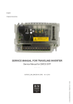
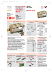
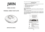
2x4 Port Matrix DVI Audio Video Switch
VS420RDVIA
*actual product may vary from photos
DE: Bedienungsanleitung - de.startech.com
FR: Guide de l'utilisateur - fr.startech.com
ES: Guía del usuario - es.startech.com
IT: Guida per l'uso - it.startech.com
NL: Gebruiksaanwijzing - nl.startech.com
PT: Guia do usuário - pt.startech.com
For the most up-to-date information, please visit: www.startech.com
Manual Revision: 09/30/2011
FCC Compliance Statement
This equipment has been tested and found to comply with the limits for a Class B digital
device, pursuant to part 15 of the FCC Rules. These limits are designed to provide reasonable
protection against harmful interference in a residential installation. This equipment generates,
uses and can radiate radio frequency energy and, if not installed and used in accordance with
the instructions, may cause harmful interference to radio communications. However, there
is no guarantee that interference will not occur in a particular installation. If this equipment
does cause harmful interference to radio or television reception, which can be determined by
turning the equipment off and on, the user is encouraged to try to correct the interference by
one or more of the following measures:
• Reorient or relocate the receiving antenna.
• Increase the separation between the equipment and receiver.
• Connect the equipment into an outlet on a circuit different from that to which the receiver
is connected.
• Consult the dealer or an experienced radio/TV technician for help.
Use of Trademarks, Registered Trademarks, and other Protected Names and
Symbols
This manual may make reference to trademarks, registered trademarks, and other
protected names and/or symbols of third-party companies not related in any way to
StarTech.com. Where they occur these references are for illustrative purposes only and do not
represent an endorsement of a product or service by StarTech.com, or an endorsement of the
product(s) to which this manual applies by the third-party company in question. Regardless
of any direct acknowledgement elsewhere in the body of this document, StarTech.com hereby
acknowledges that all trademarks, registered trademarks, service marks, and other protected
names and/or symbols contained in this manual and related documents are the property of
their respective holders.
Instruction Manual
Table of Contents
Introduction.............................................................................................1
Packaging Contents.................................................................................................................................. 1
System Requirements............................................................................................................................... 1
Installation...............................................................................................2
Hardware Installation............................................................................................................................... 2
Driver Installation....................................................................................................................................... 2
Specifications...........................................................................................4
Technical Support...................................................................................5
Warranty Information.............................................................................5
Instruction Manual
i
Installation
Packaging Contents
•
•
•
•
•
•
DVI Video and Audio Matrix Switcher
Instruction Manual
IR External Sensor
Power Adapter
Remote Control
Set of Ear-Mounts for Rack Mounting
Input Connection
Step 1
Connect the DVI video port of the computer to the Source 1 port of the Video Matrix
as shown.
Step 2
Connect the speaker port of the computer to the Audio port of Source 1 as shown.
Instruction Manual
1
Step 3
Repeat Step 1 and 2 on Source 2, as shown.
Output Connection
Step 1
Connect your monitor to port 1 of the Video Matrix Switch, as shown
Step 2
Connect a pair of speakers to port 1 of the Video Matrix Switch, as shown.
Instruction Manual
2
Step 3
Repeat Step 1 and 2 on the audio and video output channels for port 2, if necessary.
Step 4
Apply power to the Video Matrix Switch as shown.
Instruction Manual
3
Basic Operations
Front Panel Operation
Once the unit has been powered on, all 4 red LEDs should be illuminated. Due to the
factory default settings, if all 4 red LEDs are blinking, source 1 is empty. When all 4 LEDs
are always ON then a video signal has been detected at source 1.
Setting Monitor Routes
Route Source 1 or 2 to Monitors 1 through 4 Respectively
Step 1
Press the desired port, for example “4”.
Step 2
LEDs 1 and 2 should now be blinking.
•
•
•
•
1 represents Source 1.
2 represents Source 2.
Green means the video signal has been detected.
Red means no video signal has been detected.
Instruction Manual
4
Step 3
Press 1 or 2 within 3 seconds to select Source 1 or Source 2. After selecting, LED 4 will
become either red or orange.
• Red means Source 1 is selected
• Orange means Source 2 is selected
Step 4
Repeat Step 1 through 3 to route other ports.
Remote Control Operation
Using the included external sensor, the user has two methods of achieving remote
control of the unit within a range of 5 meters. Without the external sensor connected
to the unit, the remote control communicates with the internal sensor. Conversely,
when the external sensor is connected to the unit, the internal sensor is disabled.
Remote controlling is achieved through communication between the remote and the
external sensor.
Setting Monitor Routes
Route Source 1 or 2 to Monitors 1 through 4 repsectively
Step 1
Press the desired port (ie. 4).
Step 2
Press S1 or S2 to route Source 1 or Source 2 to Monitor 4.
Step 3
Repeat Step 1 and 2 to route other ports.
Optional: If you would like to turn the video or audio ports ON or OFF, you may do so
by pressing the video and audio buttons.
Instruction Manual
5
Advanced Operations
Front Panel Operation
Turn the Video ON/OFF
Step 1
Press the desired port (ie. 2).
Step 2
Press and hold “Option” and the LED light 1 will light up. If the LED light is green it
means the video output device is powered on. If it is red, then the monitor is powerd
off.
Step 3
Press 1 to turn off Monitor 2.
Step 4
If necessary, repeat these steps to turn on Monitor 2.
Instruction Manual
6
Turn the Audio ON/OFF
Step 1
Press the desired port (ie. 1).
Step 2
Press and hold “Option” and the LED light 2 will light up. If the LED light is green, it
means the audio output is powered on. If it is red, then the audio output is powered
off.
Step 3
Press 2 to turn off the audio of Monitor 1.
Step 4
If necessary repeat Step 1 through Step 3 to turn on the audio of Monitor 1.
Instruction Manual
7
Turn ON/OFF the Auto Scan
In the auto scan mode, the Video Matrix Switch automatically swithces between
Source 1 and Source 2 sequentially for a particular monitor.
Step 1
Press the desired port (ie. 4).
Step 2
Press and hold Option.
Step 3
Press 3 to turn on the auto scan mode for Monitor 4.
Step 4
If necessary, repeat Step 1 through Step 3 to turn off the auto scan mode for
Monitor 4.
Instruction Manual
8
Set the Auto Scan Time Interval
Step 1
Press 3 and 4 at the same time.
Step 2
All four LEDs should be blinking. Press one to set the auto scan time interval.
•
•
•
•
1 represents 8 seconds
2 represents 15 seconds
3 represents 30 seconds
4 represents 45 seconds
Reset the Unit to its Default Settings
1. Power off the Video Matrix Switch.
2. Press and hold Option.
3. Power on the Video Matrix Switch.
4. Press 1 to reset everything back to the default settings.
Instruction Manual
9
Unit Stack
This function allows the user to use one single remote control to command up to 16
Video Matrix Switch units.
Setting the Remote Controlling ID on the system
1. Power off the Video Matrix Switch.
2. Press and hold 1 and 2 at the same time.
3. Power on the Video Matrix Switch.
4. Release 1 and 2.
5. Select any one of the 1 through 8 remote control buttons, 4 for example. This sets
the current Video Matrix Switch remote controlling ID to 4.
6. To control the Video Matrix Switch, press Shift + 4 on the remote control. The
unit with the remote controlling ID of 4 will beep twice, and its LED will blink
continuously.
7. Repeat Steps 1 through 5 if there is more than one Video Matrix Switch unit being
cascaded. Note that each unit must be assigned a different remote controlling ID,
otherwise each will receive remote control commands simultaneously.
Optimize the Video Signal Strength
The optimal video signal strength can be adjusted to correspond to the length and
quality of the DVI cables being used. Each monitor has two different video strength
settings.
For example, were the user to change the video strength setting of Source 2 for
Monitor 3, the necessary steps would be:
1. Switch Monitor 3 to Source 2 (Refer to Basic Operations for details).
2. Press the desired port (ie. 3).
3. Press and hold Option.
4. Press 4 to turn on the video signal strength setting mode for Monitor 3.
Instruction Manual
10
5. Press 1 once or twice to adjust the input video strength of the selected port. The
colour of the LED will indicate the strength of the video signal. If it is green, the
normal strength is in use. Red indicates the use of the enhance strength feature.
OR
Press 3 once or twoce to adjust the output current of the selected port. The colour
of the LED will indicate the output current. If it is green, the normal current is in use,
while red indicates the use of the enhanced current.
OR
Press 4 one, two, three, or four times to adjust the output emphasis of the selected
port. The colour of the LED will indicate the output emphasis. If it is green, there is
no pre-emphasis, yellow, low pre-emphasis, orange, medium pre-emphasis, or red
for high pre-emphasis.
6. Once the setting is finished, press Option to exit the settings mode.
Rackmount Kit (Optional)
The following figure shows how to properly attach the optional mounting brackets to
the Video Matrix Switch unit, for use with an industrial standard, 19-inch rack cabinet.
Instruction Manual
11
Specifications
VS420RDVIA
Number of Video Source Ports
2
Number of Monitor Ports
4
Video Type
DVI
Remote Control
Yes
Remote Control Extender Jack
Yes
Push Button Control
5
LEDs
5
Hot-Plug & Play
Yes
Rack-Mounted
19” industry standard
Automatic Scan Interval
8, 15, 30, 45 seconds
DVI Cable Length (Max)
5m
Video Resolution (Max)
1600 x 1200
Monitor Connector
DVI female x 4
H x W x D (mm) (Inches)
41 x 220 x 97 (1.6 x 8.66 x 3.8)
Weight (g)
744
Operating Temperature
5~40°C
Storage Temperature
-20~60°C
Humidity
0~80%RH
Rear-Mount Brackets
1U height, included
Size
1U
Power Supply (min)
External Power Adapter, 12V DC, 1.5A
Instruction Manual
12
Technical Support
StarTech.com’s lifetime technical support is an integral part of our commitment to
provide industry-leading solutions. If you ever need help with your product, visit
www.startech.com/support and access our comprehensive selection of online tools,
documentation, and downloads.
For the latest drivers/software, please visit www.startech.com/downloads
Warranty Information
This product is backed by a two year warranty.
In addition, StarTech.com warrants its products against defects in materials
and workmanship for the periods noted, following the initial date of purchase.
During this period, the products may be returned for repair, or replacement with
equivalent products at our discretion. The warranty covers parts and labor costs only.
StarTech.com does not warrant its products from defects or damages arising from
misuse, abuse, alteration, or normal wear and tear.
Limitation of Liability
In no event shall the liability of StarTech.com Ltd. and StarTech.com USA LLP (or their
officers, directors, employees or agents) for any damages (whether direct or indirect,
special, punitive, incidental, consequential, or otherwise), loss of profits, loss of business,
or any pecuniary loss, arising out of or related to the use of the product exceed the
actual price paid for the product. Some states do not allow the exclusion or limitation
of incidental or consequential damages. If such laws apply, the limitations or exclusions
contained in this statement may not apply to you.
Instruction Manual
13
Hard-to-find made easy. At StarTech.com, that isn’t a slogan. It’s a promise.
StarTech.com is your one-stop source for every connectivity part you need. From
the latest technology to legacy products — and all the parts that bridge the old and
new — we can help you find the parts that connect your solutions.
We make it easy to locate the parts, and we quickly deliver them wherever they need
to go. Just talk to one of our tech advisors or visit our website. You’ll be connected to
the products you need in no time.
Visit www.startech.com for complete information on all StarTech.com products and
to access exclusive resources and time-saving tools.
StarTech.com is an ISO 9001 Registered manufacturer of connectivity and technology
parts. StarTech.com was founded in 1985 and has operations in the United States,
Canada, the United Kingdom and Taiwan servicing a worldwide market.