1
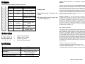
Hardware Installation
PEX2ECDP User Manual
Please note: Please note: Although PEX2ECDP supports both USB and PCI Express-based
ExpressCards, only USB-based cards offer hot-swappable connectivity. As such, please
consult the documentation that was included with your purchase of the intended
ExpressCard, to determine whether or not it supports hot-swapping.
Dual Profile PCI Express to ExpressCard Adapter
Introduction
Thank you for purchasing a StarTech.com PCI
Express to ExpressCard Adapter. This product
allows you to use an ExpressCard with your PCI
Express enabled PC.
Features
• Supports both 34 and 54 form factor
ExpressCards
• Compliant with PCI Express Base Spec.1.0a
• Works with PCI Express slots that provide
3.3V and 1.5V auxiliary power
System Requirements
• PC with an available PCI Express slot
• Windows 2000/XP/2003 Server
1. Make sure that your computer system is unplugged and that you are grounded.
2. Remove the cover of your system (see your computer's user manual for details, if necessary) and
gently turn your computer onto its side, so that the PCI Express expansion slot openings on the
motherboard are facing upwards.
3. Locate an empty PCI Express slot and remove the metal plate that covers the corresponding rear
bracket. You may need a Phillips screwdriver to perform this step. Retain the screw! You will need it to
secure the card later.
4. Gently insert the card into the empty slot, making sure it is firmly seated.
5. Secure the card in place using the screw you removed in Step 3.
6. Connect the 5-pin header provided by PEX2ECDP to an available USB header on the host computer,
noting the following diagram. Once complete, replace the cover and power on the computer.
Package Contents
•
•
•
•
PCI Express to ExpressCard Adapter (1)
Low Profile Bracket (1)
3’ 5-pin Header USB Cable (1)
User Manual (1)
Signal
Ground
USB
D+
USB
D-
USB
+5V
Please note: If the motherboard does not have a USB header available for connection, please connect
the USB Type ‘B’ connector provided by PEX2ECDP to an available USB port connected to the motherboard. Failing this, hot-plugging will not be available for inserted cards.
Pin Headers
Support, Warranty Information, and Regulatory Compliance
Statement
PEX2ECDP offers several control/status pins:
Label
Signal Name
Signal description
GND
GND
Signal ground
CKE
CLKEN
Clock Enable
OC
OC#
Over current status
SHD
SHDN#
STB
STANDBY#
KRQ
CLKRQ#
CUB
CPUSB#
CPE
CPPE#
***Please note:
1.Signal denoted with “#” indicates “low
active”.
Shut down control input.
Slow down to Hi-Z mode 2. All signals either have IC internal pullup or on-board pull-up
Standby control input
Clock Request from
device
USB device present
status
PCI Express device
present status
LED Descriptions
1
2
3
4
1
2
3
4
Green - D1 (3.3 Vout)
Yellow - D3 (1.5 Vout)
Green - D2 (Vaux)
Red - D4 (Over current)
Specifications
Bus Type
Form Factor
Connectors
Regulatory Certifications
PCI Express
34 and 54 ExpressCard
1 x 34/54 ExpressCard Slot
1 x Internal USB Type B Port
1 4-pin USB header
If you ever need help with your product, visit www.startech.com/support and access our comprehensive selection of online tools, documentation, and downloads. This product is backed by a lifetime warranty. In addition, StarTech.com warrants its products against defects
in materials and workmanship for the periods noted, following the initial date of purchase. During this period, the products may be returned
for repair, or replacement with equivalent products at our discretion.
The warranty covers parts and labor costs only. StarTech.com does not
warrant its products from defects or damages arising from misuse,
abuse, alteration, or normal wear and tear.
Limitation of Liability: In no event shall the liability of StarTech.com
Ltd. and StarTech.com USA LLP (or their officers, directors, employees
or agents) for any damages (whether direct or indirect, special, punitive, incidental, consequential, or otherwise), loss of profits, loss of
business, or any pecuniary loss, arising out of or related to the use of
the product exceed the actual price paid for the product. Some states
do not allow the exclusion or limitation of incidental or consequential
damages. If such laws apply, the limitations or exclusions contained in
this statement may not apply to you.
FCC Compliance Statement
This equipment has been tested and found to comply with the limits for
a Class B digital device, pursuant to part 15 of the FCC Rules. These
limits are designed to provide reasonable protection against harmful
interference in a residential installation. This equipment generates,
uses and can radiate radio frequency energy and, if not installed and
used in accordance with the instructions, may cause harmful interference to radio communications. However, there is no guarantee that
interference will not occur in a particular installation. If this equipment
does cause harmful interference to radio or television reception, which
can be determined by turning the equipment off and on, the user is
encouraged to try to correct the interference by one or more of the following measures:
• Reorient or relocate the receiving antenna
• Increase the separation between the equipment and receiver
• Connect the equipment into an outlet on a circuit different from that
to which the receiver is connected.
• Consult the dealer or an experienced radio/TV technician for help.
FCC, CE, ROHS
Revision A: October 11, 2007