1
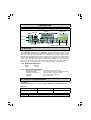
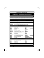
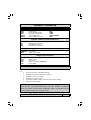
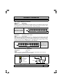
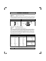
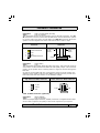
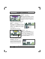
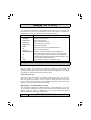
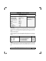
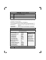
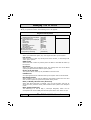
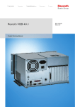
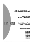
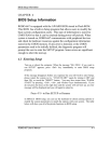
P4X4-ALH Mainboard Manual Socket 478 DDR333 ATX Mainboard Version 1.x UM-P4X4-ALH-E1 Rev 1.0V Creation Date: 02 August 2002 The P4X4-ALH Mainboard Page 1 User’s Notice Copyright This publication contains information that is protected by copyright. No part of it may be reproduced in any form or by any means or used to make any transformation adaptation without prior written permission from the copyright holders. This publication is provided for informational purposes only. The manufacturer makes no representations or warranties with respect to the contents or use of this manual and specifically disclaims any express or implied warranties of merchantability or fitness for any particular purpose. The user will assume the entire risk of the use or the results of the use of this document. The manufacturer reserves the right to revise this publication and make changes to its contents at any time, without prior notice. 2002. All Rights Reserved. Trademarks Microsoft®, MS-DOS®, WindowsTM, Windows®95 and Windows®98 are registered trademarks of Microsoft Corporation. Intel® PentiumTM4 is a registered trademark of Intel Corporation. Award is the registered trademark of Award Software, Inc. Other trademarks and registered trademarks of products appearing in this publication are the properties of their respective holders. Package Checklist This package contains the following items: • Mainboard • User’s manual • One IDE cable • One 34-pin floppy disk drive cable • One 4 CH out cable • One Driver Utility CD If any of these items are damaged or missing, please contact your dealer or sales representative for assistance. Technical Support If you require additional information or assistance during installation please contact your dealer. Your dealer will be able to provide the latest information. Page 2 The P4X4-ALH Mainboard Table Of Contents Chapter 1:- Introduction Page 5 1.1. Mainboard and PC 99 ATX External Connector Layout ............................... 5 1.2. Overview ....................................................................................................... 6 1.2.1. The P4X4-ALH Mainboard ................................................................... 6 1.2.2. Mainboard Dimensions .......................................................................... 6 1.2.3. Environmental Limitations...................................................................... 6 1.3. Features and Specifications ......................................................................... 6 1.4. System Health Monitor Functions ................................................................ 9 1.5. System Intelligence...................................................................................... 9 Chapter 2:- Hardware Installation Page 10 2.1. Installation Checklist ................................................................................... 10 2.2. Installation Steps ......................................................................................... 11 2.3. Expansion Slots, Jumpers and Internal Connectors ................................... 12 2.4. CPU, Memory and Expansion Slots .............................................................. 13 2.4.1. Installation of the CPU .......................................................................... 13 2.4.2. Memory Modules .................................................................................. 13 2.4.3. PCI Slots .............................................................................................. 14 2.4.4. AGP (Accelerated Graphics Port) Slot ...................................................... 14 2.5. Internal Connectors ..................................................................................... 15 2.5.1. Floppy Disk Drive Connector .................................................................. 15 2.5.2. Primary and Secondary IDE Connectors .................................................. 15 2.5.3. Infrared Connector (Optional) ................................................................ 15 2.5.4. CPU Fan and Chassis Fan Connectors ..................................................... 16 2.5.5. ATX Power Supply Connectors ............................................................... 16 2.5.6. CD-IN/AUX-IN Connector....................................................................... 17 2.5.7. WOL (Wake-On-LAN) Connector ............................................................ 17 2.5.8. S/PDIF Connector (Optional) ................................................................. 17 2.5.9. USB3, USB4, USB5, USB6 Connectors .................................................... 18 2.5.10. Front Audio Connector .......................................................................... 18 2.5.11. 4 CH OUT............................................................................................ 19 2.6. System Panel Buttons and LED Connectors ................................................ 20 2.6.1. PW: Power On / Off and External Suspend Switch Connector.................... 20 2.6.2. SL: Sleep LED Connector ....................................................................... 20 2.6.3. HL: IDE HDD LED Connector ................................................................. 20 2.6.4. RS: Reset Button Connector................................................................... 20 2.7. Speaker and Power LED Connectors ........................................................... 21 2.7.1. Speaker Connector................................................................................ 21 2.7.2. Front Panel Power LED .......................................................................... 21 The P4X4-ALH Mainboard Page 3 Table Of Contents 2.8. External Connectors ..................................................................................... 21 2.8.1. PS/2 Keyboard Connector ...................................................................... 21 2.8.2. PS/2 Mouse Connector .......................................................................... 21 2.8.3. Serial Port Connectors ........................................................................... 21 2.8.4. Parallel Port Connector .......................................................................... 22 2.8.5. Universal Serial Bus (USB) Ports ............................................................. 22 2.8.6. Audio/Game Connector ......................................................................... 22 2.8.7. RJ-45 (LAN Port) Connector ................................................................... 22 2.9. Jumper Settings ........................................................................................... 23 2.9.1. JP1: Keyboard Power ............................................................................ 23 2.9.2. JP3: USB 1, 2 Power ............................................................................ 23 2.9.3. JP5: CPU Clock ..................................................................................... 23 2.9.4. JP8: Check 1.5V AGP ............................................................................ 24 2.9.5. JP9: Clears CMOS ................................................................................. 24 Chapter 3:- Managing The PC BIOS Page 24 3.1. 3.2. 3.3. 3.4. 3.5. 3.6. 3.7. 3.8. 3.9. 3.10. 3.11. Award BIOS CMOS Setup Utility ............................................................... 25 Main Menu ................................................................................................. 25 Standard CMOS Setup ............................................................................... 26 Advanced BIOS Features........................................................................... 28 Advanced Chipset Features ....................................................................... 31 Integrated Peripherals .............................................................................. 34 Power Management Setup ........................................................................ 38 PNP/PCI Configuration ............................................................................. 41 PC Health Status........................................................................................ 42 Frequency/Voltage Control ....................................................................... 43 Load Fail-Safe Defaults / Load Optimized Defaults ................................. 44 3.11.1. Load Fail-Safe Defaults ....................................................................... 44 3.11.2. Load Optimized Defaults ..................................................................... 44 3.12. Set Supervisor Password and User Password .......................................... 45 3.12.1. Set Supervisor Password..................................................................... 45 3.12.2. Set User Password ............................................................................. 45 3.13. Save & Exit Setup/Exit Without Saving ................................................... 46 3.13.1. Save & Exit Setup .............................................................................. 46 3.13.2. Exit Without Saving ............................................................................ 46 Page 4 The P4X4-ALH Mainboard Introduction Chapter 1 - Introduction 1.1. Mainboard and PC 99 ATX External Connector Layout CN36: S/PDIF (Optional) CN12: IR (Optional) CN39: Front Audio CN21: CD-IN CN45: AUX-IN CN46: 4 CH OUT CN15-A: ATX CN15-D: AUX12V CN15-B: ATX12V PC 99 ATX External Connector CN16: WOL PCI PCI PCI PCI PCI PCI 6 5 4 3 2 1 CN13: CPU Fan CPU Socket CN17: Chassis Fan SPK PWRLED DIMM1 DIMM2 DIMM3 CN30: CN31: CN32: CN38: USB3 USB4 USB5 USB6 CN9: IDE1 CN10: IDE2 AGP Slot CN8: FDC System Panel and Power LED Connectors The P4X4-ALH Mainboard Page 5 Introduction PC 99 ATX External Connector CN18: GAME CN5: LPT CN35: LAN CN2: M/S CN1: K/B CN6: USB1 CN7: USB2 CN3: COM1 CN4: COM2 LINE-IN SPK-OUT / FRONT SPK-OUT MIC-IN 1.2. Overview 1.2.1. The P4X4-ALH Mainboard The P4X4-ALH mainboard is a Pentium™ 4 DDR platform. Onboard it provides three DDR DIMM slots (support up to DDR333), six USB2.0 ports, six PCI slots and one 1.5V 4X/8X AGP slot. There are also two fan connectors (for additional thermal protection) and three power supply connectors. Additionally, it comes with Onboard Audio (AC’97 6-channel), Onboard LAN [VIA VT6103 (PHY)] and WOL (Wake-On-LAN) connector that enables it to be “woken up” from a soft-off power state when it receives a signal from the LAN. Other onboard connectors include CD-IN, AUX-IN and Front Audio connectors etc. 1.2.2. Mainboard Dimensions Width 305 mm Length 230 mm 1.2.3. Environmental Limitations Operating Temperature: Required Airflow: Storage Temperature: Humidity: Altitude: 10°C to 40°C (50°F to 104°F) 50 linear feet per minute across the CPU -40°C to 70°C (-40°F to 158°F) 0 to 90% non-condensing 0 to 10 000 feet 1.3. Features and Specifications Processor The P4X4-ALH mainboard supports Intel® Pentium™ 4 Socket 478 CPUs. Chipsets Northbridge Southbridge I/O Chipset VIA P4X400 VIA VT8235 (CD) Winbond W83697HF Page 6 The P4X4-ALH Mainboard Introduction CPU Switching Voltage Regulator The mainboard is equipped with a switching voltage regulator that automatically detects a DC power supply from +1.10V to +1.85V. System Memory The mainboard uses Double Data Rate Dual Inline Memory Modules (DDR DIMM). Each mainboard has three 184-pin DIMM sockets which support 2.5V (power level) single-sided or double sided PC1600 (DDR200), PC2100 (DDR266) or PC2700 (DDR333) DDR DIMM modules. The maximum memory supported by the mainboard is 3 GB. Expansion Slots The mainboard is equipped with six dedicated PCI slots and one 1.5V 4X/8X AGP slot. Onboard Audio Features The mainboard supports Microsoft DirectSound/DirectSound 3D and AC97 Full Duplex. Onboard LAN Features The mainboard comes with Onboard LAN [VIA VT6103 (PHY)]. WOL (Wake-On-LAN) Port The mainboard supports Wake-On-LAN functionality. Word Size Data Path: Address Path: 8-bit, 16-bit, 32-bit, 64-bit 32-bit Front Side Bus Frequency (FSB) The Front Side Bus Frequency (FSB) clock is 400/533 MHz. BIOS • • • • Award BIOS, Windows 95/98 Plug and Play (PnP) compatible Supports SCSI sequential boot-up 2 Mb flash ROM for easy BIOS upgrades Supports DMI2.0 function Desktop Management Interface (DMI) The mainboard comes with DMI 2.0 built into the BIOS. The DMI utility in the BIOS will automatically record different information about your system configuration and store this information in the DMI pool, which is a part of the system board's Plug and Play BIOS. DMI, along with the appropriately networked software, is designed for easy inventory, maintenance and the simplified troubleshooting of computer systems. The P4X4-ALH Mainboard Page 7 Introduction USB2.0 Ports USB allows data exchange between your computer and a wide range of simultaneously accessible external Plug and Play peripherals. The mainboard is equipped with six USB (version 2.0) connectors. USB1 and USB2 are external connectors. They can be found on the PC 99 ATX connector. The other USB connectors are internal connectors and can be used to connect other USB devices. (Cables for the internal connectors are sold separately). Please note that the PIN assignment of the internal USB 2.0 connectors (CN30, CN31, CN32 and CN38) are follow the specifications of Intel standard. Connectors • Two • One • One • One • One • Two • One • One • One • One • One • One • One IDE connectors (support ATA 33/66/100/133) Floppy Drive connector supports up to two 2.88 MB floppy drives 20-pin ATX power supply connector 2x2 ATX 12V power supply connector 1x4 AUX12V power supply connector fan connectors CD-IN connector AUX-IN connector WOL (Wake-On-LAN) connector Front Audio connector 4-Channel out connector S/PDIF connector (optional) IR connector (optional) ATX Double Deck Ports (PC 99 color-coded connectors) • Two USB2.0 ports • Two external DB-9 serial port connectors: COM 1, COM 2 (UART) • One SPP/ECP/EPP DB-25 parallel port • One mini-DIN-6 PS/2 mouse port • One mini-DIN-6 PS/2 keyboard port • One GAME port • One LAN port (RJ-45) connector • Three audio jacks: SPK-OUT/FRONT SPK-OUT, LINE-IN and MIC-IN PCI Bus Master IDE Controller • Two PCI IDE interfaces support up to four IDE devices. • This mainboard supports ATA 33/66/100/133 hard drives. • PIO Mode 3 and Mode 4 Enhanced IDE (data transfer rate up to 16.6MB/sec.). • Bus mastering reduces CPU utilization during disk transfer. • Supports ATAPI CD-ROM, LS-120 and ZIP. Page 8 The P4X4-ALH Mainboard Introduction 1.4. System Health Monitor Functions The mainboard is capable of monitoring the following health conditions of your system: 1. Processor temperature. It has an overheat alarm. 2. VCORE/3.3V/5V/12V/-12V voltages and failure alarm. 3. Processor and chassis fan speeds. It has a failure alarm for these fans. 4. Read back capability that displays temperature, voltage and fan speed. Hardware Monitoring System Utility The mainboard comes with the Hardware Monitoring System utility contained on the CD. It is capable of monitoring the system’s hardware conditions such as the temperature of the processor, voltage, and the speed of both the CPU and chassis fans. You are allowed to manually set a range to the items being monitored. If the values are over or under the set range a warning message will automatically pop up. We recommend that you use the Default Settings, which are the ideal settings that will maintain the system in a good working condition. To install this utility, please insert the CD into the CD-ROM drive. The auto run screen (Driver Utility) will automatically appear. Click the Hardware Monitoring button, choose the chipset, model number and the OS that is installed. Please refer to the CD “Readme” file for further installation instructions. Note: Only use this utility in Windows operating systems. 1.5. System Intelligence Dual Function Power Button Depending on the setting in the Soft-Off By Power-Button field of the Power Management Setup, this switch allows the system to enter the Soft-Off or Suspend mode. RTC Timer to Power-on the System The RTC installed on the system board allows your system to automatically power-on at a set date and time. Wake-On-LAN Ready The Wake-On-LAN function allows the network to remotely wake up a Soft Power Down (Soft-Off) PC. Your LAN card must support the remote wakeup function. The 5V SB power source of your power supply must be at least 720mA. ACPI Ready The mainboard is designed to meet the ACPI (Advanced Configuration and Power Interface) specification. ACPI has energy saving features that support OS Direct Power Management (OSPM) for round the clock PC operation. The P4X4-ALH Mainboard Page 9 Hardware Installation Chapter 2 - Hardware Installation 2.1. Installation Checklist The following is a checklist of all the expansion slots, jumpers and connectors that should be configured on your mainboard before you can run your PC. Installation Checklist Expansion Slots and Sockets CPU Socket DIMM Slots PCI Slots AGP Slot Intel® Pentium™ 4 Socket 478 CPU Three 184-pin Slots Six 32-bit PCI Slots One 1.5V 4X/8X Accelerated Graphics Port Slot Internal Connectors CN8 CN9 CN10 CN12 CN13 CN15-A CN15-B CN15-D CN16 CN17 CN21 CN30/31 CN32/38 CN36 CN39 CN45 CN46 Floppy Drive Connector Primary IDE Secondary IDE Infrared CPU Fan ATX Power Supply ATX 12V Power Supply Auxiliary ATX 12V Power Supply Wake-On-LAN Connector Chassis Fan CD Audio In Universal Serial Bus 3/4 Universal Serial Bus 5/6 Sony Phillips Digital Interface Front Audio Connector Auxiliary In Connector 4 CH OUT FDC IDE1 IDE2 IR (optional) CPU Fan ATX ATX12V AUX12V WOL FAN2 CD-IN USB3/4 USB5/6 S/PDIF (optional) Front Audio AUX-IN 4-Channel Audio Out External Connectors CN1 CN2 CN3 CN4 PS/2 Keyboard Connector PS/2 Mouse Connector Serial Port 1 Serial Port 2 K/B M/S COM1 COM2 “Optional”: These are manufacturing options. Page 10 The P4X4-ALH Mainboard Hardware Installation Installation Checklist (Continued) CN5 CN6 CN7 CN18 CN35 Parallel Port Universal Serial Port 1 Universal Serial Port 2 Audio/GAME Port RJ-45 (LAN) Connector LPT USB1 USB2 AUDIO/GAME LAN Speaker and Power LED Connectors PW SL HL RS Power On/Off and Suspend Switch Connector Standby LED Connector HDD LED Connector Reset Button Connector Speaker and Power LED Connectors PWRLED SPK Power LED Speaker Connector Jumpers and Switches JP1 JP3 JP5 JP8 JP9 K/B Power USB1,2 Power CPU Clock Check 1.5V AGP (optional) Clear CMOS 2.2. Installation Steps You need to complete the following installation steps before you can use your PC. • Check and set the mainboard settings; • • • • • Install the Central Processing Unit (CPU); Install the memory modules; Install the expansion cards; Connect the ribbon cables, panel wires and power supply; Setup the system BIOS. Before you start installing your mainboard we strongly recommend that you use a grounded anti-static mat. We further recommend that you attach an anti-static wristband, which is grounded at the same location as the mat, to your wrist. The P4X4-ALH Mainboard Page 11 Hardware Installation 2.3. Expansion Slots, Jumpers and Internal Connectors DIMM1 DIMM2 DIMM3 1 1 CN13: FAN1 JP1 JP3 1 CPU CN15-D: AUX12V CN15-B: ATX12V CN15-A: ATX VIA P4X400 1 CD-IN AUX-IN 1 PCI 1 PCI 2 6 CN8: FDC AGP 4X/8X Slot JP8 1 CN9: IDE1 CN39: Front Audio CN10: IDE2 JP5 VIA VT8235 PCI 3 1 CN46: 4 CH OUT PCI 5 1 IR Page 12 CN38:USB6 CN32:USB5 1 JP9 1 1 CN27: FAN2 1 CN31:USB4 CN30:USB3 PCI 6 CN16 WOL PWR LED Speaker 1 1 System Panel Buttons and LED Connectors PCI 4 The P4X4-ALH Mainboard Hardware Installation 2.4. CPU, Memory and Expansion Slots 2.4.1. Installation of the CPU To install your processor, please complete the following set of instructions: 1. Locate a small dot marked on the top of the CPU. This mark indicates Pin of the CPU. 2. Locate Pin 1 for the Socket on the mainboard. 3. There is a lever on the side of the socket. First push this lever sideways and then lift it to a 90-degree angle. 4. Insert the CPU into the Socket. Please make sure that Pin 1 for the CPU is inserted into Pin 1 of the Socket. 5. When the CPU is installed correctly push the lever back into place. 6. Install a proper heat sink with cooling fan for proper heat dissipation. Failing to install a heat sink with cooling fan may cause overheating which will burnout your CPU and damage your mainboard. IMPORTANT: CPU COOLING FAN Please ensure that you have an approved heat sink with cooling fan. Without a proper heat sink with cooling fan you will damage both the mainboard and the CPU. 2.4.2. Memory Modules The mainboard has three 184-pin DDR DIMM slots which are located on the right-hand side of the board. To install the DIMM’s into these slots, make sure the white lever at each side of the slot has been pulled down to an angle of approximately 45°. Make sure that the DIMM is in the correct orientation. Place the DIMM on the slot and push down firmly.The white levers will come back up and lock the module in place. Supports 128 MB, 256 MB, 512 MB and 1 GB technologies for x8 and x16 devices. Top View of a 184-pin DIMM Slot 52 pins 40 pins Important: The DIMM’s can only be fitted into the slots in one orientation. Make sure that the DIMM’s are in the correct orientation and the pins are correctly aligned before you insert them. The P4X4-ALH Mainboard Page 13 Hardware Installation NOTE: “Out Of Memory” Error Message If you have installed more than 512 MB of RAM and are running Microsoft Windows Millennium Edition, Windows 98 Second Edition, Windows 98 or Windows 95 you may experience memory problems. Two symptoms of these problems are being unable to run an MS-DOS session while you are running Windows or the computer may stop responding while Windows is starting. There are three possible solutions to this problem: 1) Reduce the amount of memory Vcache uses to 512 MB or less by altering the MaxFileCache setting in the System.ini file. 2) Use the System Configuration Utility to reduce the amount of memory Windows uses to 512 MB or less. 3) Reduce the memory installed on your computer to 512 MB or less. This problem can also occur if an Advanced Graphic Port (AGP) video adapter is used. 2.4.3. PCI Slots The mainboard comes with six PCI slots. They are located on the left-hand side of the board. Both PCI and PCI expansion cards may require IRQ’s. This mainboard complies with Plug and Play (PnP) specifications. Whenever a PnP compliant card is added the system will automatically be configured and the IRQ’s will be assigned automatically. Top View of a 32-bit PCI Slot 11 pins 49 pins 2.4.4. AGP (Accelerated Graphics Port) Slot AGP is a dedicated bus slot. It operates at 66 MHz and transfers data at a rate up to 533 MB(8x). This allows 3D applications to run more smoothly. The mainboard comes with a 1.5V AGP slot which is able to support 4x/8X AGP cards. Top View of an AGP Slot 21 pins Page 14 41 pins The P4X4-ALH Mainboard Hardware Installation 2.5. Internal Connectors 2.5.1. Floppy Disk Drive Connector Connector: CN8 (FDC) Type: 34 pin block The FDC connector can support two floppy drives. It is located at the front of the mainboard. To connect, use the ribbon cable that has been provided. Make sure that the red strip is connected to Pin 1 of the connector. Top View of a Floppy Disk Drive Connector Pin 1 17 pins 2.5.2. Primary and Secondary IDE Connectors Connector: CN9 (IDE1)/CN10 (IDE2) Type: 40 pin block The mainboard has two IDE connectors: a primary and secondary. Each IDE connector can support two IDE drives. The mainboard each can therefore support up to four IDE devices. If you install two hard drives, you need to configure the second drive to Slave mode in the BIOS setup. Please refer to your hard drive manual for the appropriate jumper settings. Top View of an IDE Connector Pin 1 20 pins 2.5.3. Infrared Connector (Optional ) Connector: CN12 (IR) Type: 5 pin The IR connector supports an optional wireless transmitting and receiving module. Please make sure the Pin 1 location. Top View of an IR Connector 1 2 3 4 5 5V DC No Connection IR Reciever Ground IR Transmitter Front View of an IR Connector IR Receiver Ground IR Transmitter 5V DC The P4X4-ALH Mainboard Page 15 Hardware Installation 2.5.4. CPU Fan and Chassis Fan Connectors Connector: CN13 (FAN1)/CN17 (FAN2) Type: 3 pin The cooling fans must be connected to their respective power connectors. If you have installed the hardware-monitoring feature you will be able to monitor the rotating speed of the CPU cooling fan in your Windows operating system. Top View of a Fan Connector 1 Ground 2 3 +12V DC Fan Signal Front View of a Fan Connector +12V DC Fan Signal Ground 2.5.5. ATX Power Supply Connectors Connector: CN15-A/CN15-B/CN15-D Type: 20 pin block/2x2 12V/1x4 AUX12V The mainboard comes with three onboard power supply connectors labeled CN15-A, CN15-B and CN-15D. CN15-A and CN15-B are regular ATX12V power supply connectors. CN15A and CN15D are regular ATX power supply connectors. The auxiliary power supply connector (CN15-D) is for a +12V and +5V power supply. These increased power supplies are necessary to provide extra power for the slot. The ATX 12V power supplies are all downward compatible with standard ATX power supplies. ATX Connectors Pin Assignments CN15-A CN15-B Pin 1 +3.3VDC Pin 11 +3.3VDC Pin 1 COM Pin 2 +3.3VDC Pin 12 -12VDC Pin 2 COM Pin 3 COM Pin 13 COM Pin 3 +12VDC Pin 4 +5VDC Pin 14 PS_ON# Pin 4 +12VDC Pin 5 COM Pin 15 COM Pin 6 +5VDC Pin 16 COM Pin 1 +12VDC Pin 7 COM Pin 17 COM Pin 2 COM Pin 8 PWR_OK Pin 18 -5VDC Pin 3 COM Pin 9 +5VSB Pin 19 +5VDC Pin 4 +5VDC Pin 10 +12VDC Pin 20 +5VDC Page 16 CN15-D The P4X4-ALH Mainboard Hardware Installation 2.5.6. CD-IN/AUX-IN Connector Connector: CN21 (CD-IN)/CN45 (AUX-IN) Type: 4 pin un-housed The mainboard has one CD-IN connector and one AUX-IN connector. The CDIN connector is used to connect the CD ROM audio out and allows the system to receive audio input from the CD ROM. The AUX-IN connector allows the system to receive signals from other audio devices like a radio or tape. Top View of a CD/AUX-IN Connector 1 2 3 4 Left Channel CD/AUX-IN Ground Ground Right Channel CD/AUX-IN Front View of a CD/AUX-IN Connector Left Channel CD-IN/ AUX-IN Right Channel CD-IN/ AUX-IN Ground Ground 2.5.7. WOL (Wake-On-LAN) Connector Connector: CN16 (WOL) Type: 3 pin The mainboard has a WOL (Wake-On-LAN) connector. This connector must be connected to a LAN card that has Wake-On-LAN (WOL) output. This connector powers up the system when a wakeup packet or signal is received through the LAN card. In order to use the WOL LAN card to trigger the power on the PC system, the switching power supply must have the ability to provide a driving current of at least 720 mA and be connected to a “5V standby” voltage. Top View of a WOL Connector Front View of a WOL Connector Ground 1 5V_SB 2 3 Ground WOL 5V_SB WOL 2.5.8. S/PDIF Connector (Optional) Connector: CN36 (S/PDIF) Type: 4 pin un-housed The Sony Phillips Digital Interface, S/PDIF, connector is a digital interface that can be used to improve the quality of the sound output from your system. The P4X4-ALH Mainboard Page 17 Hardware Installation 2.5.9. USB3, USB4, USB5, USB6 Connectors Connector: CN30 (USB 3)/CN31 (USB 4)/CN32 (USB5)/CN38 (USB6) Type: 5 pin You already have two USB2.0 ports available, USB1 and 2 (see external connectors). The internal USB connectors allow you to add on an optional kit to expand the total number of USB ports available. The mainboard has four internal USB2.0 connectors (CN30/CN31/CN32/CN38). This enables you to use an extra four USB devices. Cable for these additional connectors needs to be purchased separately. Note: The PIN assignment of the internal USB 2.0 connectors (CN30, CN31, CN32 and CN38) are follow the specifications of Intel standard. Front View of USB Ports Top View of USB Ports USB3/5 USB3/5 USB4/6 USB4/6 5 Data + 1 VCC 2 VCC 3 Data- 4 Data- 5 Data+ 6 Data+ 7 Ground 8 Ground 6 Data + 3 Data - 7 Ground 1 VCC 4 Data - 8 Ground 10 NC 2 VCC 10 NC 2.5.10. Front Audio Connector Connector: CN39 (Front Audio) Type: 10 pin This connector is designed to be used with a Front-Utility Panel. The utility panel was developed so that a user is able to bring the speaker out, microphone in connectors to the front of their PC. This makes things like plugging in speakers and earphones much less troublesome. Front Audio Connector Pin 2 1 Page 18 4 3 6 5 8 7 10 9 Pin 1 MIC-IN (Left) 2 Ground 3 MIC-IN (Right) 4 NC 5 LINE-OUT R 6 NC 7 NC 8 Key 9 LINE-OUT L 10 NC The P4X4-ALH Mainboard Hardware Installation 2.5.11. 4-Channel OUT Connector Connector: CN46 (4 CH OUT) Type: 6 pin This mainboard has the capability of 5.1 channel sound surrounded function, specifically sound effect that is destined for DVD or DTS home entertainment playback. In order to fully get the sound surrounded effect, this connector has to be used together with the Audio portion of the PC 99 ATX external connector on the mainboard. Special audio cable for this connector is attached. Please refer the following drawings or schematics to have the right connection for your sound systems. 4 CH OUT Connector 1 2 3 4 5 6 Pin Pin 1 Rear Left Channel 2 Rear Right Channel 3 Ground 4 Ground 5 Center 6 LFE (WOOFER) Audio Cable for 4 CH OUT Connector Cable Rear Left & Rear Right Jack Center & LFE (Woofer) Jack Bracket Rear Left & Rear Right Jack Center & LFE (Woofer) Jack Bracket Speakers connection for 5.1 channel sound systems on P4X4-ALH mainboard. Front Left & Front Right Jack The P4X4-ALH Mainboard Page 19 Hardware Installation 2.6. System Panel Buttons and LED Connectors The following System Panel Buttons and LED Connectors (2 x 4 pins) can be found at the front of the mainboard on the left hand side. PW= Power On/Off and Suspend Switch Connector SL = Sleep LED Connector HL = HDD LED Connector RS = Reset Button Connector RS: Reset Control Ground HL: +5V DC Pull Up Ground SL: Signal Pin Ground PW:+5V DC Pull Up Ground PIN 1 Top View of the System Panel and LED Connectors 2.6.1 PW: Power On/Off and External Suspend Switch Connector The Power On/Off connector has two functions. It can be the Power Switch or Suspend Switch of your PC system. You can either choose “Delay 4 Sec” or “Instant OFF” . Option 1: If you choose “Delay 4 Sec.” In the BIOS CMOS Setup, the function of “PW” will be: A. When the system power is "OFF", press this switch, the system will power on. B. When system power is "ON”, you can select two different modes: Mode 1: Press and hold the Power ON button for less than 4 seconds and then release it. The system will be turned into Suspend mode (turned into the GREEN mode) When the system is in the Suspend mode: Press the Power on button (less than 4 seconds), the system will return to Full-ON mode. Press and hold the Power On Button for more than 4 seconds, the system will be powered off. Mode 2: Press and hold the Power ON button for more than 4 seconds, the system will be completely powered off. Option 2: If you choose “Instant OFF.” In the BIOS CMOS Setup, the power switch will operate like a normal ON / OFF Power button. 2.6.2. SL: Sleep LED Connector When lighted, the LED indicates that the AC power is ON but your system is switched OFF. When unlighted, the LED indicates that either the AC power is OFF/Unconnected or the system is switched ON. 2.6.3. HL: IDE HDD LED Connector Any read and write activity by the HDD will turn this LED on. 2.6.4. RS: Reset Button Connector If you connect this connector, you will be able to reset you computer by pressing the reset button at the front of the chassis. Page 20 The P4X4-ALH Mainboard Hardware Installation 2.7. Speaker and Power LED Connectors 2.7.1. Speaker Connector (SPKR) SPKR Connect your chassis speaker to this four-pin connector. It allows you to hear systems beeps and warnings sound. PIN 1 2.7.2. Front Panel Power LED PIN 1 (PWRLED) The chassis power LED connector can be connected to the four-pin connector. When you turn your system on, this LED will also be turned on. +5V DC Speaker Signal Speaker Signal Speaker Signal +5V DC Ground Ground NC PWRLED Top View of the Speaker and Power LED Connectors 2.8. External Connectors 2.8.1. PS/2 Keyboard Connector Connector: Type: CN1 (K/B) 6 pin female This connector only supports a PS/2 keyboard plug. If you have a standard AT size (large DIN) keyboard plug, you need to use a mini DIN adapter. 2.8.2. PS/2 Mouse Connector Connector: Type: CN2 (M/S) 6 pin female This connector only supports a PS/2 mouse plug. If a PS/2 mouse is detected then IRQ 12 will be directed to CN2. 2.8.3. Serial Port Connectors Connector: CN3 (COM 1)/CN4 (COM2) Type: 9 pin male One serial port is available for a mouse and other serial devices. (I/O addresses used are 3F8H/2F8H/3E8H/2E8H and IRQ3/IRQ4, selected by CMOS setup.) The P4X4-ALH Mainboard Page 21 Hardware Installation 2.8.4. Parallel Port Connector Connector: CN5 (LPT) Type: 25 pin female. This parallel port is used by printers which support the SPP, EPP and ECP modes IRQ7 or IRQ5 can be selected. The ECP mode will use either DMA 3 or DMA 1 (which can be selected by the BIOS setup program). 2.8.5. Universal Serial Bus (USB) Ports Connector: CN6 (USB 1)/CN7 (USB 2) Type: 4 pin female Two USB ports are available for connecting USB devices. The mainboard is also equipped with an expansion connector that supports two additional USB external connectors. (The USB cable is not included in the package). USB 2 USB 1 2.8.6. Audio/Game Connector SPK-OUT/Front SPK-OUT MIC-IN Connector: CN18 Type: 15 pin female The Audio/Game port connector is a dual purpose connector. It can either be used to connect a joystick to the computer for game participation, or it can be used to attach an external MIDI device. All these motherboards have 3D audio interfaces onboard. LINE-IN 2.8.7. RJ-45 (LAN Port) Connector Connector: CN35 (LAN) The mainboard comes with onboard 10/100 Mb Fast Ethernet Network. The RJ-45 connector allows you to easily connect to a Local Area Network (LAN) through a network hub. Page 22 The P4X4-ALH Mainboard Hardware Installation 2.9. Jumper Settings Jumpers are built on the mainboard to allow the user flexibility to configure the mainboard settings to meet their specific requirements. The mainboard comes with five jumpers, three 3-pin and two 2-pin jumper. When there is no jumper cap inserted into the jumper it is called “OPEN.” When a cap is inserted into the jumper it is known as a “SHORT.” Below are examples of short settings or open settings on a jumper. Two-Pin Jumper Three-Pin Jumper PIN: 1 Open Short SHORT 2 3 Pin 1/Pin 2 PIN: 1 2 3 Pin 2/Pin 3 2.9.1. JP1: Keyboard Power Type: 3 pin (K/B Power) Default: Pin 1 and Pin 2 Short This jumper allows you to Power On your system using your mouse or keyboard. If you short Pin 1 and Pin 2 then the “Keyboard/Mouse Wakeup” function will be disabled. If Pin 2 and Pin 3 are short then the “Keyboard/ Mouse Power On” function will be enabled. If you choose to enable this option then you need to enable the POWER ON field in the Power Management Setup - IRQ/Event Activity Detect Menu of the BIOS setup. 2.9.2. JP3: USB1, USB2 Power Type: 3 pin Default: Pin 1 and Pin 2 Short This jumper allows you to select the voltage that is supplied to USB1 and USB2. You have two choices: 5 V (pin 1 and pin 2 short) or standby 5 V (pin 2 and pin 3 short). Some USB devices may not follow the standard USB power specifications. If you are using such a device it may unstable. If you do experience problems try to change the setting on Pin 2 and Pin 3. This might help solve this problem. 2.9.3. JP5: CPU Clock Type: 2 pin Default: Short If this jumper is short, the mainboard will automatically detect the CPU clock speed FSB 400 MHz or 533MHz. If this jumper is open then the FSB will be forced to be 533 MHz. The P4X4-ALH Mainboard Page 23 Hardware Installation 2.9.4. JP8: Check 1.5V AGP (otional) Type: 2 pin Default: Open This jumper can be used to check if your AGP card is 1.5V or 3.3V. If you open this jumper then the system will check to see what type of AGP card you are using. If a 3.3V card is detected your system will not boot. Note: The jumper must be made Open after the AGP card has been inserted into the slot. If this jumper remains Short the system will boot with both a 1.5V and 3.3V AGP card. Warning: if you are using a 3.3V AGP card you may damage your system. 2.9.5. JP9: Clear CMOS Type: 3 pin Default: Pin 1 and Pin 2 Short If you have made an improper setting in the BIOS setup and your computer is not functioning, or if you have forgotten your password, you can use this jumper to clear the CMOS memory and to reconfigure your system. To 1. 2. 3. 4. clear the CMOS, please follow these instructions: Turn the system power off and unplug your computer; Insert the jumper cap on Pin 2 and Pin 3 for 3 ~ 5 seconds; Pull out the jumper cap and replace it on Pin 1 and Pin 2; Turn your PC on and run the BIOS setup program. Page 24 The P4X4-ALH Mainboard Managing The PC BIOS Chapter 3 - Managing the PC BIOS 3.1. Award BIOS CMOS Setup Utility Once you have installed the mainboard you still need to setup the BIOS before you can run your PC. The EEPROM on the mainboard stores the AWARD BIOS CMOS Setup Utility, which allows you to configure your system. When you want to configure or make any changes to the configuration of your system BIOS you must run the BIOS CMOS Setup Utility. GETTING STARTED Every time you start your computer, the system provides you with an opportunity to run the BIOS CMOS Setup Utility. As soon as you turn on your system, press the <Delete> button to activate the BIOS CMOS Setup Utility. If your computer finishes the POST (Power-On-Self-Test) the BIOS CMOS Setup Utility will not be activated. If your computer completes the POST you need to restart the system to activate the BIOS CMOS Setup Utility. To restart the system, you can either turn the power off, press the reset button on your chassis or press the <Ctrl> + <Alt> + <Delete> button. In all three cases the system will restart and, to activate the BIOS CMOS Setup Utility, you must immediately press the <Delete> button. 3.2. Main Menu Phoenix - AwardBIOS CMOS Setup Utility 4Standard CMOS Features 4Frequency/Voltage Control 4Advanced BIOS Features Load Fail-Safe Defaults 4Advanced Chipset Features Load Optimized Defaults 4Integrated Peripherals Set Supervisor Password 4Power Management Setup Set User Password 4PNP/PCI Configuration Save & Exit Setup 4PC Health Status Exit Without Saving ← ↑ ↓ → : Select Item Esc : Quit Time, Date, Hard Disk Type ... Note! BIOS software is continuously updated therefore the BIOS menus and the descriptions that are given in this manual are for reference purposes only. The P4X4-ALH Mainboard Page 25 Managing The PC BIOS Navigation Keys You will notice a legend bar at the bottom of the main menu. The keys in this legend bar show you how to navigate through the setup menus. The table below lists the control keys with their corresponding functions: Control Key Function Up Arrow Moves to the previous item. Down Arrow Moves to the next item. Left Arrow Moves to the item on the left. Right Arrow Moves to the item on the right. Enter Selects the desired item. F1 Displays the help screen for the selected feature. Esc key Exits to the previous screen. PgUp(-)/PgDn(+) Modifies or changes the content of the highlighted item. F5 Restores the previous CMOS values to the current page setup. This will not restore the previous values for any other pages. F7 Loads the SETUP default values from BIOS default table, (only the current page setup will be loaded). F10 Saves changes to the CMOS and exits the setup. 3.3. Standard CMOS Setup (This menu is on page 27) Date (mm : dd : yy) Sets your system to the date that you specifiy (usually the current date). The format is month, day, and year. Press the right or left arrow key to move to the desired field (month, date, year). Press the PgUp or PgDn key to increment the setting, or type the desired value into the field. Time (hh : mm : ss) Sets your system to the time you specify (usually the current time). The format is hour, minute, second. The time format is based on the 24-hour military-time clock. For example, 1 P.M. is 13:00:00. Press the right or left arrow key to move to the desired field. Press the PgUp or PgDn key to increment the setting, or type the desired value into the field. IDE Primary / Secondary Master / Slave This mainboard supports four IDE Hard Drives. These fields allow you to set your Hard Drive parameters. Move the selection bar to the IDE Hard Drive you want to configure. Press the "ENTER" key. If you select “AUTO” the system BIOS will detect the HDD type automatically. Page 26 The P4X4-ALH Mainboard Managing The PC BIOS Phoenix - AwardBIOS CMOS Setup Utility Standard CMOS Features Date (mm : dd : yy) Time (hh : mm : ss) 4IDE 4IDE 4IDE 4IDE Primary Master Primary Slave Secondary Master Secondary Slave Fri, Jul 26, 2002 15 : 48 : 52 [Maxtor 52049H4] [None] [None] [None] Drive A Drive B Floppy 3 Mode Support 1.44, 3.5 in None [Disabled] Video Halt On EGA/VGA All Errors Base Memory Extended Memory Total Memory 640K 65472K 1024K Item Help Menu Level 4 Change the day, month, year and century Drive A /B The mainboard can support up to two floppy disk drives. These two selection fields allow you to select the floppy drives that are installed on your computer. Select the correct specifications for the diskette drive(s) installed on your computer. Floppy 3 Mode Support If you have installed a 3.5 inch high capacity floppy disk drive you need to enable this option. If you have not installed one of these drives use the default setting. Diskette Drive Type of Disk Drive Capacity None 360K 1.2M 720K 1.44M 2.88M No diskette drive installed 5-1/4 inch PC-type standard drive 5-1/4 inch AT-type high-density drive 3-1/2 inch single-sided drive 3-1/2 inch double-sided drive 3-1/2 inch double-sided drive 360 KB 1.2 MB 720 KB 1.44 MB 2.88 MB 5.25 in 5.25 in 3.5 in 3.5 in 3.5 in Video This field selects the type of primary video subsystem that is on your computer. The BIOS CMOS Setup Utility will automatically detect the correct video type. The P4X4-ALH Mainboard Page 27 Managing The PC BIOS EGA/VGA Enhanced Graphics Adapter/Video Graphics Array. For EGA, VGA , SEGA, SVGA or PGA monitor adapters CGA 40 Color Graphics Adapter power up in 40 column mode CGA 80 Color Graphics Adapter power up in 80 column mode MONO Monochrome adapter includes high resolution monochrome adapters Halt On This field allows you to decide which errors, detected during the Power On Self Test (POST), will halt the system. Base Memory / Extended Memory / Total Memory This field displays the amount of memory detected by the system during boot up. This is a display only field. You cannot make any changes to this field. Base Memory: Extended Memory: Total Memory: Indicates the memory installed below the conventional 1MB space. Indicates the memory installed above the 1MB space. Indicates the total memory installed in the PC system. 3.4. Advanced BIOS Features Phoenix - AwardBIOS CMOS Setup Utility Advanced BIOS Features Virus Warning CPU L1 & L2 Cache CPU L2 Cache ECC Checking Quick Power On Self Test First Boot Device Second Boot Device Third Boot Device Boot Other Device Swap Floppy Drive Boot Up Floppy Seek Boot Up NumLock Status Typematic Rate Setting X Typematic Rate (Chars/Sec) X Typematic Delay (Msec) Security Option PS/2 Mouse Function Control OS Select For DRAM > 64 MB HDD S.M.A.R.T Capability Video BIOS Shadow Full Screen Logo Show Small Logo (EPA) Show Page 28 [Disabled] [Enabled] [Enabled] [Enabled] [Floppy] [HDD-0] [LS120] [Enabled] [Disabled] [Enabled] [On] [Disabled] 6 250 [Setup] [Enabled] [Non-OS2] [Disabled] [Enabled] [Disabled] [Disabled] Item Help Menu Level 4 Allows you to choose the VIRUS warning feature for IDE Hard disk boot sector protection. If this function is enabled and someone attempts to write data into this area, BIOS will show a warning message on screen and alarm beep. The P4X4-ALH Mainboard Managing The PC BIOS Virus Warning When you enable the virus warning you will receive a warning message whenever a program (specifically, a virus) attempts to write to the boot sector or the partition table of the hard disk drive. If you receive such a message you should immediately run an anti-virus program. Keep in mind that this feature only protects the boot sector and not the entire hard drive. Disk diagnostic programs that access the boot sector table can trigger the virus-warning message. If you run such a program, recommend that you first disable the virus warning. CPU L1 & L2 Cache This field can be used to enable or disable the system’s primary (L1) or secondary (L2) cache. CPU L2 Cache ECC Checking When you select Enabled, the ECC checking will ensure that the data stored on the L2 cache is accurate. Quick Power On Self Test If enabled the amount of time required to run the power-on self-test (POST) will decrease. A quick POST skips certain steps. We recommend that you disable quick POST. It is better to find a problem during POST than to lose data during your work. First / Second / Third Boot Device These fields allow you to decide the boot sequence of your bootable devices such as Floppy Drive, Hard Drive, CD ROM...etc Boot Other Device When this field is enabled you will be able Boot your computer from a different device, not your HDD or FDD. Swap Floppy Drive This field is effective only in systems with two floppy drives. When Enabled is selected physical drive B is assigned to logical drive A, and physical drive A is assigned to logical drive B. Boot Up Floppy Seek When enabled, the BIOS tests (seeks) floppy drives to determine whether they have 40 or 80 tracks. Only 360-KB floppy drives have 40 tracks; drives with 720 KB, 1.2 MB, and 1.44 MB capacity all have 80 tracks. Very few modern PCs have 40-track floppy drives so we therefore recommend that you set this field to Disabled to save time. The P4X4-ALH Mainboard Page 29 Managing The PC BIOS Boot Up NumLock Status This controls the state of the NumLock key when the system boots. This field is toggled between On or Off. When it is on the numeric keypad generates numbers instead of controlling the cursor operations. When it is off the numeric keypad controls cursor operations and does not generate numbers. Typematic Rate Setting The keyboard controller determines the rate at which the keystrokes from the keyboard are repeated. If enabled the typematic rate and the typematic delay can be selected. Typematic Rate The rate a character will repeat itself on the screen when you hold down a key. Typematic Delay This is the delay time (Msec) before the repetition of characters starts. Security Option This field allows you to select the “Setup” or “System” security option. It works concurrently with the “ Set Supervisor Password” in the main menu. When the "Setup" option is selected, you will be prompted to enter your "Password" before you can start the BIOS CMOS Setup Utility. When you select "System" option, you will be prompted to enter your password in order to load the Operating System. TIP: Forgot your password then clear the RTC RAM If you happen to forget your password you can use Jumper 9 (JP9) to clear the password by erasing the CMOS Real Time Clock (RTC) Ram. Please see section 2.9.5. on page 24. OS Select For DRAM > 64MB Only select OS2 if you are running an OS/2 operating system with a RAM greater than 64 Mb. Otherwise, for all other operating systems, use the default setting “Non-OS2” HDD S.M.A.R.T Capability You may “enable” this option if your Hard Drive supports the S.M.A.R.T technology (Self Monitoring Analysis Reporting Technology) feature. S.M.A.R.T will monitor and report your Hard Drive health status. Ask your Hard Drive vendor for more information. NOTE: Using this feature may decrease system performance. Video BIOS Shadow These fields allow you to change the Video BIOS location from ROM to RAM. Information access is faster through RAM than ROM. Therefore when you enable this option you will enhance your system performance. Page 30 The P4X4-ALH Mainboard Managing The PC BIOS 3.5. Advanced Chipset Features Phoenix - AwardBIOS CMOS Setup Utility Advanced Chipset Features 4DRAM Clock/Drive Control 4AGP & P2P Bridge Control 4CPU & PCI Bus Control Memory Hole System BIOS Cacheable Video RAM Cacheable Delay Prior To Thermal [Press Enter] [Press Enter] [Press Enter] [Disabled] [Disabled] [Disabled] [16 Min] Item Help Menu Level 4 Dram Clock Drive Control This field allows you to select the FSB and DRAM frequency. When you press enter the following menu will appear. Phoenix - AwardBIOS CMOS Setup Utility DRAM Clock/Drive Control Current FSB Frequency Current DRAM Frequency DRAM Clock DRAM Timing X SDRAM CAS Latency X Bank Interleave X Precharge to Active (Trp) X Active to Precharge (Tras) X Active to CMD (Trcd) XDRAM Command Rate DRAM Burst Len Write Recovery Time 100 MHz 133 MHz [By SPD] [By SPD] 3 [Disabled] 3T 7T 3T 2T Command [4] [3T] Item Help Menu Level 44 4Current FSB Frequency The setting for this field will be automatically selected by the BIOS. 4Current Dram Frequency The setting for this field will be automatically detected by the BIOS. The value that is selected in derived from the RAM clock. 4DRAM Clock When you press enter you will have three options: By SPD :The BIOS will automatically detect the actual DRAM Clock. 100 MHz :The DRAM clock speed will be PC1600 (100 MHz DDR). 133 MHz :The DRAM clock speed will be PC2100 (133 MHz DDR). 166MHz :The DRAM clock speed will be PC2700 (166 MHz DDR). 4DRAM Timing This field enables/disables you from selecting the values for following six fields manually. These (six) fields determine the DRAM read/write timing. If you select By SPD then those fields will be automatically configured by the system BIOS. (The performance parameters of the installed memory chips (DRAM) determines the value in those fields.) The P4X4-ALH Mainboard Page 31 Managing The PC BIOS If you select Manual you will need to enter the values for those fields. You should not change the values of those fields from the factory setting unless you have installed new memory that has a different performance rating than the original DRAMs. 4SDRAM CAS Latency Before SDRAM can execute a read command that it receives, there is a delay time, which is measured in clock cycles (CLK). Some memory modules are unable to deal with short delay times. We recommend that you set this delay time between 1.5, 2, 2.5 and 3 CLK’s (the default is 3). If your system becomes unstable we recommend that you increase the delay time. AGP & P2P Bridge Control When you press enter the following menu will appear: Phoenix - AwardBIOS CMOS Setup Utility AGP & P2P Bridge Control AGP Aperture Size AGP Mode AGP Driving Control X AGP Driving Value AGP Fast Write AGP Master 1 WS Write AGP Master 1 WS Read DBI Output for AGP Trans. [128M] [4X] [Auto] DA [Disabled] [Disabled] [Disabled] [Disabled] Item Help Menu Level 44 4AGP Aperture Size This field selects the size of the Accelerated Graphics Port (AGP) aperture. The aperture is a portion of the PCI memory address range dedicated for graphics memory address space. Host cycles that hit the aperture range are forwarded to the AGP without any translation. The default is 128MB. You may increase this memory when you need to have faster access for 3D graphics applications (e.g. games). 4AGP Driving Control The recommended setting for this field is the default “Auto”. If you have an unstable AGP card you may use this field to choose the appropriate settings. If you do need to tune the timing, please consult your AGP Card manual or Vendor. 4AGP Driving Value This item allows you to adjust the AGP driving force. 4AGP Master 1 WS Write When Enabled, writes to the AGP are executed with one-wait states. 4AGP Master 1 WS Read When Enabled, reads to the AGP are executed with one-wait states. Page 32 The P4X4-ALH Mainboard Managing The PC BIOS CPU & PCI Bus Control When you select this field the following menu will appear: Phoenix - AwardBIOS CMOS Setup Utility CPU & PCI Bus Control CPU to PCI Write Buffer PCI Master 0 WS Write PCI Delay Transaction [Enabled] [Enabled] [Disabled] Item Help Menu Level 44 4CPU to PCI Write Buffer If enabled, writes from the CPU to the PCI bus will be buffered so that the CPU will not have to wait until the write is completed before starting another write cycle. 4PCI Master 0 WS Write If enabled, writes to the PCI bus are executed with zero wait states 4PCI Master 0 WS Write The chipset has an embedded 32-bit posted write buffer to support delay transaction cycles. Select enabled to support compliance with PCI specification version 2.1. Memory Hole You can reserve this area of system memory for ISA adapter ROM. When this area is reserved, it cannot be cached. The user information of peripherals that need to use this area of system memory usually discusses their memory requirements. System BIOS Cacheable Selecting “Enabled” allows caching of the system BIOS ROM. This results system performance. However, if any program writes to this memory area, a system error may occur. Video RAM Cacheable Select Enabled allows caching of the video RAM, resulting in better system performance. However, if any program writes to this memory area, a system error may occur. Delay Prior to Thermal This item allows you to select the delay time before the P4 CPU Thermal Function is enabled. If you are using NT 4.0 you must be active to prevent the system from hanging. The options are: 4 min, 8 min, 16 min and 32 min. The P4X4-ALH Mainboard Page 33 Managing The PC BIOS 3.6. Integrated Peripherals Phoenix - AwardBIOS CMOS Setup Utility Integrated Peripherals 4 VIA OnChip IDE Device 4 VIA OnChip PCI Device 4 SuperIO Device Init Display First OnChip USB Controller USB Keyboard Support IDE HDD Block Mode [Press Enter] [Press Enter] [Press Enter] [PCI Slot] [All Enabled] [Disabled] [Enabled] Item Help Menu Level 4 VIA OnChip IDE Device When you press enter the following menu will appear: Phoenix - AwardBIOS CMOS Setup Utility VIA OnChip IDE Device OnChip IDE Channel0 OnChip IDE Channel1 IDE Prefetch Mode Primary Master PIO Primary Slave PIO Secondary Master PIO Secondary Slave PIO Primary Master UDMA Primary Slave UDMA Secondary Master UDMA Secondary Slave UDMA [Enabled] [Enabled] [Enabled] [Auto] [Auto] [Auto] [Auto] [Auto] [Auto] [Auto] [Auto] Item Help Menu Level 44 4OnChip IDE Channel 0/1 The chipset contains a PCI IDE interface with support for two IDE channels. To activate the primary IDE interface select Enabled. If you want to disable the onboard IDE 1 and/or 2, then select Disabled and this interface will be deactivated. 4OnChip IDE Channel 0/1 The chipset contains a PCI IDE interface with support for two IDE channels. To activate the primary IDE interface select Enabled. If you want to disable the onboard IDE 1 and/or 2, then select Disabled. 4IDE Prefetch Mode The onboard IDE drive interfaces supports IDE pre-fetching for faster drive access. If you install a primary and/or secondary add-in IDE interface which does not support pre-fetching set this field to Disabled. Page 34 The P4X4-ALH Mainboard Managing The PC BIOS 4Primary/Secondary, Master/Slave PIO The four IDE PIO (Programmed Input/Output) fields let you set a PIO mode (0-4) for each of the four IDE devices that the onboard IDE interface supports. Modes 0 through 4 provide successively increased performance. In Auto mode, the system automatically determines the best mode for each device. 4Primary/Secondary, Master/Slave UDMA Ultra DMA/66 implementation is possible only if your IDE hard drive supports it and the operating environment includes a DMA driver (Windows 98 OSR2 or a third-party IDE bus master driver). If your hard drive and your system software both support Ultra DMA/66, select Auto to enable BIOS support. VIA OnChip PCI Device When you select this field the following menu will appear: Phoenix - AwardBIOS CMOS Setup Utility VIA OnChip PCI Device VIA-3058 AC97 Audio VIA-3043 OnChip LAN Onboard LAN Boot ROM [Auto] [Enabled] [Disabled] Item Help Menu Level 44 4VIA-3058 AC97 Audio If you want to enable the on-chip audio capabilities of your system you need use the default setting “Auto”. If you install an add on sound card you must disable this field. 4VIA-3043 OnChip LAN This field allows you to decide whether you want this support or not. If you select “Enabled” the BIOS will automatically detect the LAN chip. If you select “Disabled” the Bios will not detect any on-chip LAN function. 4Onboard LAN Boot ROM This field can be used to enable or disable the Boot ROM of the onboard VIA 10/100 Adapter LAN Chip to support the boot up of a diskless client functionality unit. SuperIO Device When you press enter the following menu on page 36 is shown 4Onboard FDC Controller Select Enabled if your system has a floppy disk controller (FDC) installed on the system board and you want to use it. If you install an add-in FDC or the system has no floppy drive, select Disabled in this field. 4Onboard Serial Port 1/2 These two selection fields allow you to select the I/O address and corresponding interrupts for the first and second serial port. The P4X4-ALH Mainboard Page 35 Managing The PC BIOS Phoenix - AwardBIOS CMOS Setup Utility SuperIO Device Onboard FDC Controller Onboard Serial Port 1 Onboard Serial Port 2 UART Mode Select RxD, TxD Active IR Transmission Delay UR2 Duplex Mode Use IR Pins Onboard Parallel Port Parallel Port Mode EPP Mode Select ECP Mode Use DMA Game Port Address Midi Port Address Midi Port IRQ [Enabled] [3F8/IRQ4] [2F8/IRQ3] [Normal] [Hi, Lo] [Enabled] [Half] [IR-Rx2Tx2] [378/IRQ7] [SPP] [EPP1.7] [3] [201] [330] [10] Item Help Menu Level 4 4UART Mode Select Your system may offer a variety of infrared modes on the second serial port. The options are Standard, HPSIR or ASKIR. 4RxD, TxD Active This field allows you to set the IR reception/transmission polarity as high or low. To determine which polarity is appropriate you must refer to the documentation for your IR peripheral. This field is usually found under the Onboard Serial Port 2 option. If you disable the Onboard Serial Port 2 option then you will probably not be able to configure this field. 4IR Transmission Delay This field allows you to “Enable” or “Disable” the IR Transmission Delay. 4UR2 Duplex Mode This field appears in an infrared port mode. You have two options: half or full duplex function. The full duplex mode allows bi-directional transmission at a single time where as the half duplex mode only allows transmission in one direction at a time. This setting depends on the nature of your IR peripheral device. Check the IR device’s manual to determine the appropriate setting. 4Use IR Pins To determine the correct settings for the TxD and RxD signals of your IR peripheral component, you need to consult the components manual. 4Onboard Parallel Port This item allows you to determine the I/O address and the IRQ for the onboard parallel port. The default settings are adequate and should not give you any problems. If they do you can try to change them. Page 36 The P4X4-ALH Mainboard Managing The PC BIOS 4Onboard Parallel Mode This field allows you to select an operating mode for the onboard parallel (printer) port. Select Normal, Compatible, or SPP unless you are certain your hardware and software both support one of the other available modes. 4EPP Mode Select This field allows you to choose the EPP version you want to use. We recommend that you use EPP 1.9 for the best performance but if you do you may have some connection problems so try setting it to EPP 1.7. 4ECP Mode Use DMA This item allows you to select a DMA channel for the parallel port for use during ECP. 4Game Port Address This field allows you to select the I/O address for the onboard game port. The default is 201. 4Midi Port Address This field allows you to select the I/O address for the onboard MIDI port. The default is 330. 4MIDI Port IRQ This field allows you to select the IRQ for the onboard MIDI port. The default is 10. Init Display First This field allows a user, with two graphics cards installed on his system, to select which graphics card will be activated first: either the PCI graphics card or the AGP graphics card. If you have only installed one graphics card the BIOS will automatically detect it and you do not need to set this field. OnChip USB Controller This field allows you to enable or disable the onboard USB controller. USB Keyboard Support This field should only be enabled if you are using a USB keyboard. If you are not using this kind of keyboard you should disable it. IDE HDD Block Mode Block mode is also known as block transfer, multiple commands, or multiple sector read/write. If your IDE hard drive supports block mode select “Enabled” for automatic detection of the optimal number of block read/writes per sector the drive can support. The P4X4-ALH Mainboard Page 37 Managing The PC BIOS 3.7. Power Management Setup Phoenix - AwardBIOS CMOS Setup Utility Power Management Setup ACPI Function ACPI Suspend Type Power Management Option HDD Power Down Suspend Mode Video Off Option Video Off Method MODEM Use IRQ Soft-Off by PWRBTN PWRON After PWR-Fail 4 IRQ/Event Activity Detect [Enabled] [S1(POS)] [User Define] [Disable] [Disable] [Suspend -> Off] [Blank Screen] [3] [Instant-Off] [Off] [Press Enter] Item Help Menu Level 4 ACPI function This item allows you to enable/disable the Advanced Configuration and Power Management (ACPI). ACPI Suspend Type This field selects the S1(POS) (Power On Suspend) suspend state mode. Power Management This category allows you to select the degree of power saving. The choices are shown in the table below. Min. Power Saving Minimum power management. Suspend Mode = 1 hr. Max. Power Saving Maximum power management -- ONLY AVAILABLE FOR SL CPU. Suspend Mode = 1 min. User Defined Allows you to set each mode individually. When not disabled, each of the ranges are from 1 min. to 1 hr. except for HDD Power Down which ranges from 1 min. to 15 min. and disable. HDD Power Down When enabled and after the set time of system inactivity, the hard disk drive will be powered down while all other devices remain active. Suspend Mode When enabled, after the set time of system inactivity, all devices except the CPU will be shut off. Video Off Option When enabled, this feature allows the VGA adapter to operate in a power saving mode. Page 38 The P4X4-ALH Mainboard Managing The PC BIOS Always On Monitor will remain on during power saving modes. Suspend --> Off Monitor blanked when the systems enters the Suspend mode. Modem Use IRQ This determines the IRQ which the MODEM can use for Power Saving purposes. This mainboard has the ACPI feature designed on the board and it will “wake-up” automatically when it detects an incoming modem Ring-in signal. Before you can use the Ring-in signal to wakeup your PC system, you have to install the “External” modem to your PC system and tell the PC system which serial port connects to the modem by selecting the IRQ in this field. (Officially COM1 uses IRQ4) Video Off Method This determines the manner in which the monitor goes blank. V/H SYNC+Blank This selection will cause the system to turn off the vertical and horizontal synchronization ports and write blanks to the video buffer. Blank Screen This option only writes blanks to the video buffer. DPMS Support Select this option if your monitor supports the Display Power Management Signaling (DPMS) standard of the Video Electronics Standards to select video power management values. MODEM Use IRQ This determines the IRQ which the MODEM can use for power saving purposes. This mainboard has the ACPI feature designed on the board and it will “wakeup” automatically when it detects an incoming modem Ring-in signal. Before you can use the Ring-in signal to wakeup your PC system, you have to install the “External” modem to your PC system and tell the PC system which serial port connects to the modem by selecting the IRQ in this field, (officially, COM 1 uses IRQ4, and COM 2 uses IRQ3) Soft-Off by PWRBTN Pressing the power button for more than 4 seconds forces the system to enter the Soft-Off state when the system has “hung”. PWRON After PWR Fail See the following table for all the options. Off: When the power returns after an AC power failure the system’s power is off. You must press the Power button to power-on the system FormerSts: When power returns after an AC power failure, the system will return to the state where you left off before the power failure occurred. If the system’s power is off when the AC power failure occurred, it will remain off when the power returns. If the system’s power is on when the AC power failure occurred, the system will power-on when the power returns. The P4X4-ALH Mainboard Page 39 Managing The PC BIOS IRQ/Event Activity Detect When you press the "Enter" the following menu will appear: Phoenix - AwardBIOS CMOS Setup Utility IRQ/Event Activity Detect PS2KB Wakeup Select PS2KB Wakeup from S3/S4/S5 X Power Button Lock PS2MS Wakeup from S3/S4/S5 VGA LPT & COM HDD & FDD PCI Master PowerOn by PCI Card LAN Resume RTC Alarm Resume X Date (of Month) X Resume Time (hh:mm:ss) 4IRQs Activity Monitoring [Hot Key] [Disabled] [Enabled] [Disabled] [OFF] [LPT/COM] [ON] [OFF] [Disabled] [Disabled] [Disabled] 0 0 : 0 : 0 [Press Enter] Item Help Menu Level 4 4VGA When you enable this option, any VGA signal will wake up the system. 4LPT & COM When this field is “ON” any activity from these devices, or their IRQ’s will wake up the system. 4HDD & FDD When this field is “ON” any activity from the HDD or the FDD will wake up the system. 4PCI Master When you enable the PCI Master mode, any activity from one of the listed system peripheral devices wakes up the system. 4Power On by PCI Card The system can be woken up by the PME# on the PCI card. 4LAN Resume An input signal from the LAN will wake up the system from a soft off state. 4RTC Alarm Resume When enabled, you can use the following two fields to select the time and date to wake up the PC system from power saving mode. 4Date (of Month)/Resume Time (hh:mm:ss) When RTC Alarm Resume is enabled, your can set the date and time at which the RTC (real-time clock) alarm awakens the system from Suspend mode. 4IRQs Activity Monitoring The following is a list of IRQ’s, Interrupt ReQuests, which can be exempted much as the COM ports and LPT ports above can. When an I/O Page 40 The P4X4-ALH Mainboard Managing The PC BIOS Device wants to gain the attention of the operating system, it signals this by causing an IRQ to occur. When the operating system is ready to respond to the request, it interrupts itself and performs the service. Note: When set On, activity will neither prevent the system from going into a power management mode nor awaken it. Phoenix - AwardBIOS CMOS Setup Utility IRQs Activity Monitoring Primary IRQ3 IRQ4 IRQ5 IRQ6 IRQ7 IRQ8 IRQ9 IRQ10 IRQ11 IRQ12 IRQ13 IRQ14 IRQ15 INTR (COM 2) (COM 1) (LPT 2) (Floppy Disk) (LPT 1) (RTC Alarm) (IRQ2 Redir) (Reserved) (Reserved) (PS/2 Mouse) (Coprocessor) (Hard Disk) (Reserved) [ON] [Disabled] [Enabled] [Enabled] [Enabled] [Enabled] [Disabled] [Disabled] [Disabled] [Disabled] [Enabled] [Enabled] [Enabled] [Disabled Item Help Menu Level 4 3.8. PNP/PCI Configuration Phoenix - AwardBIOS CMOS Setup Utility PnP/PCI Configurations PNP OS Installed Reset Configuration Data Resources Controlled By × IRQ Resources PCI/VGA Palette Snoop Assign IRQ For VGA Assign IRQ For USB [No] [Disabled] [Auto(ESCD)] [Press Enter] [Disabled] [Enabled] [Enabled] Item Help Menu Level 4 Select Yes if you are using a Plug and Play capable operating system. Select No if you need the BIOS to configure non-boot devices. PNP OS Installed This item allows you to determine if a PnP OS is installed or not. Reset Configuration Data Normally, you leave this field Disabled. If you have installed a new add-on and the system reconfiguration has caused such a serious conflict that the operating system cannot boot then select Enabled. Selecting Enabled will reset the Extended System Configuration Data (ESCD). The P4X4-ALH Mainboard Page 41 Managing The PC BIOS Resources controlled By Award Plug and Play BIOS has the capacity to automatically configure all of the boot and Plug and Play compatible devices. However, this capability means absolutely nothing unless you are using a Plug and Play operating system such as Windows 98. IRQ Resources When resources are controlled manually, assign each system interrupt a type, depending on the type of device using the interrupt PCI/VGA Palette Snoop Some display cards are non-standard VGA cards (such as graphics accelerators and MPEG cards) which may not display color properly on your screen. If this field is Enabled it may correct the problem. If you have a normal display card then leave this field Disabled as the default setting . Assign IRQ For VGA/USB A system’s IRQs are limited. Sometimes you may need to use more IRQ signals for your add-on cards. BIOS allows you to disable the IRQ which is supposed to be connected to the VGA and USB ports. If you choose to disable the IRQ on the VGA or USB port, the IRQ will be released and becomes available for other devices. Please make sure that you have a USB or VGA adapter that does not need an IRQ before you select Disabled. Assign IRQ For VGA/USB A system’s IRQs are limited. Sometimes you may need to use more IRQ signals for your add-on cards. BIOS allows you to disable the IRQ which is supposed to be connected to the VGA and USB ports. If you choose to disable the IRQ on the VGA or USB port, the IRQ will be released and becomes available for other devices. Please make sure that you have a USB or VGA adapter that does not need an IRQ before you select Disabled. 3.9. PC Health Status Phoenix - AwardBIOS CMOS Setup Utility PC Health Status CPU Warning Temperature Current CPU Temperature Current CPU FAN Speed Current CHASSIS FAN Speed Vcore (V) + 3.3 (V) +5 V + 12 V - 12 V VBAT (V) 5VSB (V) Shutdown Temperature Page 42 [Disabled] 55ºC/131ºF 4821 RPM 0 RPM 1.74 V 3.41V 4.75 V 12.09 V -12.11 V 2.99 V 5.26 V [Disabled] Item Help Menu Level 4 The P4X4-ALH Mainboard Managing The PC BIOS CPU Warning Temperature This field allows you to select an operating temperature range for your CPU. If the CPU temperature moves out of this range, any warning mechanism you have programmed into your system will be activated. Current CPU Temp. This field shows the current temperature for CPU 1. Current CPU FAN Speed This field shows you the present CPU Cooling FAN1 speed. Current Chassis FAN Speed This field shows you the present CPU Cooling FAN2 speed. Vcore This field and the files below show you the current system voltage Shutdown Temperature When the system reaches a certain maximum temperature the system will automatically shutdown. 3.10. Frequency/Voltage Control Phoenix - AwardBIOS CMOS Setup Utility Frequency/Voltage Control CPU Clock Ratio Auto Detect DIMM/PCI Clk Spread Spectrum CPU Clock [8X] [Enabled] [Disabled] [100MHz] Item Help Menu Level 4 CPU Clock Ratio This field can be used to adjust the FSB (Front Side Bus) ratio. The default (minimum adjustment) that can be made is X8. This shows the ratio range. Auto Detect DIMM/PCI Clk When “Enabled” is selected, the mainboard will detect the presence of devices on DIMM and PCI slots. When there is no device present on some of the PCI or DIMM connectors, the clock on the related DIMM and PCI slot will be disabled to reduce the Electro-Magnetic Interference (EMI). Spread Spectrum When Spread Spectrum is enabled, the EMI radiation on this mainboard will be reduced. The P4X4-ALH Mainboard Page 43 Managing The PC BIOS CPU Clock This field allows a timing combination for the CPU to be selected. There is a large range of possible combinations (+/- 1MHz to 132MHz). If Default is selected the BIOS will use the clock values for the CPU card. 3.11. Load Fail-Safe Defaults / Load Optimized Defaults Phoenix - AwardBIOS CMOS Setup Utility 4Standard CMOS Features 4Frequency/Voltage Control 4Advanced BIOS Features Load Fail-Safe Defaults 4Advanced Chipset Features Load Optimized Defaults 4Integrated Peripherals Set Supervisor Password 4Power Management Setup Set User Password 4PNP/PCI Configuration Save & Exit Setup 4PC Health Status Exit Without Saving Esc : Quit F9 : Menu in BIOS ← ↑ ↓ → : Select Item Load Fail-Safe / Optimized Defaults 3.11.1. Load Fail-Safe Defaults This option loads troubleshooting default values which are permanently stored on the BIOS ROM Chip. If you made changes to the BIOS settings and your system has become unstable, you can change it back to the default settings. If you have made many changes to the BIOS settings and you are not sure which setting is causing the problem then you should choose this option. This will load the minimal performance settings and stabilize your system. 3.11.2. Load Optimized Defaults There is CMOS memory on the mainboard that can be used to store the system settings. If you don't know how to use the Award BIOS CMOS Setup Utility to select the settings, you may use this field to load the optimized defaults which are defined in the system BIOS. Our engineer recommends the Optimized Defaults. If this option is selected it will give a series of parameters that will ensure the reliability and performance of your PC. If you lose your CMOS data or you don’t know how to complete the setup procedure, you may use this option to load the Optimized default values from the BIOS default table. If the CMOS data is corrupted, or if you selected some CMOS settings and find that the PC system becomes very unstable, you should try to load the optimized default values first and then re-configure the BIOS. Page 44 The P4X4-ALH Mainboard Managing The PC BIOS 3.12. Set Supervisor Password and User Password Phoenix - AwardBIOS CMOS Setup Utility 4Standard CMOS Features 4Frequency/Voltage Control 4Advanced BIOS Features Load Fail-Safe Defaults 4Advanced Chipset Features Load Optimized Defaults 4Integrated Peripherals Set Supervisor Password 4Power Management Setup 4PNP/PCI Configuration Set User Password Save & Exit Setup 4PC Health Status Exit Without Saving Esc : Quit F9 : Menu in BIOS ← ↑ ↓ → : Select Item Change / Set / Disable Password 3.12.1. Set Supervisor Password The “SUPERVISOR PASSWORD” is for you to control unauthorized access to your BIOS CMOS Setup or Booting into the your PC system. The Supervisor Password option is used together with the Security Option in section 3.5. When "Setup" is selected in the Security Option: If you want to change any BIOS setting, you will have to key-in the Supervisor Password so that you can start the BIOS CMOS Setup Utility and change the system setting. When "System" is selected in Security Option: Whenever you turn on the PC, it will request the user to enter the Password in order to boot up your system. Without the correct password, the PC system will stop and the operating system will not be loaded. 3.12.2. Set User Password The User Password can be used to check the user's authority. However, this password entry is different from the "SUPERVISOR PASSWORD". The User Password has a different function to the "Supervisor Password" and the "Security Option" setup in Section 3.5: A. When there is the password stored in "SUPERVISOR PASSWORD" 1. When "Setup" is selected in the Security Option: When you use the "User Password" to log into the BIOS can only view the BIOS settings, but you cannot change ting you can change is the "User Password" and you can EXIT SETUP" and "EXIT WITHOUT SAVING" from the main The P4X4-ALH Mainboard setup program, you them. The only setalso select "SAVE & menu. (If you use Page 45 Managing The PC BIOS the Supervisor Password to log into the PC system, you will have complete rights to all the BIOS settings. 2. When "System" is selected in Security Option: When you turn on the PC system, it will request that you enter the Password. Without the correct password, the PC system will stop and the operating system won't be loaded. B. When there is no password stored in "SUPERVISOR PASSWORD" 1. When "Setup" is selected in Security Option: Users can use the "User Password" to log into the BIOS setup program, and they can change any of the BIOS settings. 2. When "System" is selected in Security Option: When you turn on your PC, you will be requested to enter the Password. Without the correct password, the PC system will stop and the operation system will not be loaded. 3.13. Save & Exit Setup/Exit Without Saving Phoenix - AwardBIOS CMOS Setup Utility 4Standard CMOS Features 4Frequency/Voltage Control 4Advanced BIOS Features Load Fail-Safe Defaults 4Advanced Chipset Features Load Optimized Defaults 4Integrated Peripherals Set Supervisor Password 4Power Management Setup Set User Password 4PNP/PCI Configuration Save & Exit Setup 4PC Health Status Exit Without Saving Esc : Quit F9 : Menu in BIOS ← ↑ ↓ → : Select Item Save Data to CMOS & Exit SETUP / Abandon all Data & Exit SETUP 3.13.1. Save & Exit Setup This option will save all the setup values to CMOS RAM and exit the SETUP utility. Move the selection bar to “SAVE & EXIT SETUP” and press the “Enter” key, then type “Y” and press the “Enter” key again. The values you have entered will be saved and all the information stored in the CMOS memory. 3.13.2. Exit Without Saving This option will exits the setup utility without saving any of the values you changed in the CMOS RAM. If you do not want to save any of the changes, or settings you selected in the BIOS SETUP utility, move the selection bar to the “EXIT WITHOUT SAVING” option. Press the “Enter” key. Then press “Y”. Page 46 The P4X4-ALH Mainboard