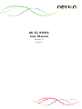
1
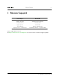
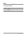
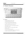
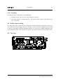
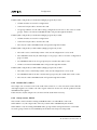
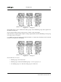
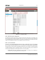
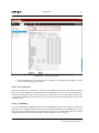
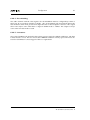
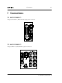
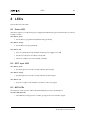
AV-3G-XMUX
User Manual
Revision: B
2015-04-07
nevion.com
Contents
1
Nevion Support
5
2
Revision History
6
3
Product Overview
7
3.1
7
4
5
Summary
Introduction
8
4.1
Extra 3G functions
8
4.1.1
8
Large mode
4.2
Signal flow
9
4.3
Asynchronous data transport
9
4.3.1
De-embedding
9
4.3.2
Embedding
10
4.4
Audio output muting
10
4.5
Top view
10
Specifications
11
5.1
SD HD and 3G SDI
11
5.1.1
Error detection
11
5.1.2
Optical input-PIN
11
5.1.3
Optical laser 13T
12
5.1.4
Optical lasers 13T, 15T, CxxxxT
12
5.1.5
Optical lasers Dxxxx
12
5.2
5.3
AES3 audio
12
5.2.1
C1 backplane
13
5.2.2
C2 and C3 backplanes
13
5.2.3
AAV-3G-XMUX-C2 backplane (with one of the AES8 audio converters)
13
Asynchronous Data
13
5.3.1
Packet or UART mode
14
5.3.2
GPI mode
14
5.3.3
Connector
14
5.4
GPI input/alarms
14
5.5
Latencies
14
5.5.1
15
SD
5.5.2
6
15
Configuration
16
6.1
DIP switch routing
17
6.1.1
AES direction/destination selection
18
6.1.2
Routing
19
6.1.3
Assigning the audio generator
20
6.2
Other DIP Switches
20
6.2.1
DIP config mode SW3.1
20
6.2.2
DMUX LED mode, SW3.2
20
6.2.3
3G High group mode SW3.3
20
6.2.4
Disable SRCs, SW3.4
21
6.2.5
Group remove, SW3.5
21
6.2.6
Fallback generator control, SW3.6
22
6.2.7
EDH insert, SW3.7
22
6.2.8
24 bit (SD), SW3.7
22
6.3
DIP configuration examples
22
6.4
Multicon GYDA
24
6.4.1
Web interface
24
6.4.2
Video input switching
24
6.4.3
Video generator
25
6.4.4
Signal integrity
27
6.4.5
Transport and shuffling of audio groups
28
6.4.6
Audio generator
28
6.4.7
Mono Audio Shuffler
28
6.4.8
Label generator
29
6.4.8.1
6.4.9
7
HD/3G
Time code auto display
RS422 Data port configuration
29
30
6.4.9.1
Data transmission
30
6.4.9.2
Data latencies
31
6.4.9.3
Embedding
31
6.4.9.4
De-embedding
32
6.4.9.5
Limitations
32
Connections
33
7.1
33
AV-3G-XMUX-C1
8
9
7.2
AV-3G-XMUX-C2
33
7.3
AV-3G-XMUX-C3
34
7.4
DB-25
34
7.5
Modular jack 8P8C
35
LEDs
36
8.1
Status LED
36
8.2
SDT Input LED
36
8.3
AES LEDs
36
GPI alarms
38
9.1
38
Laser kill GPI3 input
10
General environmental requirements
39
11
Product Warranty
40
A
Materials declaration and recycling information
41
A.1
Materials declaration
41
A.2
Recycling information
41
Nevion Support
5
1 Nevion Support
Nevion Europe
Nevion USA
Nevion Europe
P.O. Box 1020 3204
Sandefjord, Norway
Nevion USA
1600 Emerson Avenue Oxnard,
CA 93033, USA
Support phone 1:
+47 33 48 99 97
Support phone 2: +47 90 60 99 99
Toll free North
America: (866) 515-0811
Outside North America: +1 (805) 247-8560
E-mail: support@nevion.com
See http://www.nevion.com/support/ for service hours for customer support globally.
AV-3G-XMUX User Manual Rev. B
Revision History
6
2 Revision History
Rev.
Date
Comments
B
2015-03-02
Removed mixer references. Added reference to the mono shuffler block. TMLed. Added
Multicon figures.
1
2011-10-20
Changed optical overload.
0
2011-08-25
First revision
AV-3G-XMUX User Manual Rev. B
Product Overview
7
3 Product Overview
3.1 Summary
• SD, HD and 3D digital uncompressed video.
• De-embed and embed all groups of audio.
• Copy or move audio groups without additional delay.
• De-embed 8 AES3 digital audio and non-audio signals.
• Embed 8 AES3 digital audio and non-audio signals.
• Applies sample rate converters on the AES inputs when needed.
• Mono shuffle four signals.
• Optical laser output options, including CWDM and DWDM.
• Optical input option.
• Transport of asynchronous serial data.
• Generates video and audio signals including on screen label generator.
• De-glitches correctly synchronized switched video.
AV-3G-XMUX User Manual Rev. B
Introduction
8
4 Introduction
The AV-3G-XMUX is a highly integrated audio embedding module in the Flashlink range, offering
simultaneous embedding and de-embedding of eight AES3 stereo digital audio channels from a
digital 3G, HD or SD serial video signal.
The module has two main processing blocks. One processes the video stream and the packet data,
the other processes the audio. The packet processing core forms a group router which can route
embedded audio between groups without any extra delay.
The AV-3G-XMUX audio core is an AES3 audio router. The received embedded audio and the
AES3 inputs are the sources in the router. The embedded output groups and AES3 outputs are
the destinations. This feature may be used to perform stereo channel swapping.
A mono shuffler is integrated into the stereo router. The sources to the shuffler are the same
sources as in the stereo router. The outputs from the shuffler provide four extra stereo sources in
the audio router. Each shuffler output has a configurable delay up to 1.37s.
There are 8 AES ports and each may be used as either an input or an output. The sample rate
converters may be inserted by the module when needed, or the user can disable them. Data signals
such as Dolby E will always be embedded transparently without using the sample rate converters.
All embedding and de-embedding is with synchronous 48 kHz audio.
The unit may be ordered with optical transmitter and receiver options. The laser options range
from the standard -7.5dBm 1310nm to the DWDM units. The receiver may be PIN.
The module has signal generators for audio and video for test and line-up applications. The internal video generator may be used as a fall-back source that is used if the both the electrical and
the optical input signals fail. This allows uninterrupted transmission of embedded audio.
4.1 Extra 3G functions
AV-3G-XMUX will process the extra 8 audio pairs in 3G SDI.
The module has two different user interfaces in the Gyda System Controller. The ’Large mode’ is
used if the additional audio in the 3G video signals are to be used.
The ’small’ mode represents the module in a similar way to the other Nevion XMUX embedders
and only shows the traditional audio groups 1 to 4. The other 3G audio groups are still transported
through the module.
4.1.1 Large mode
This functionality should be enabled if the user needs access to the audio in groups 5 to 8 in layer
A video OR audio in the second link of Layer B video.
In ’Large mode’ the module can still only embed 4 audio groups: Either the conventional 4 groups
or the four additional groups in 3G video.
AV-3G-XMUX User Manual Rev. B
Introduction
9
All 8 audio groups are de-embedded from 3G video both in layer A and layer B. The audio signals
are available in the audio matrix which is considerably expanded in this mode.
The four audio groups that are not embedded by the module will be transported without any
delay. This means that the use of the module with different video formats will be predictable. If
the module is to be used to embed the extra 3G audio signals then it will transport the normal 4
audio groups transparently. If SD or HD video is then fed to the same embedder, the embedders
will be disabled. De-embedding from the normal groups will be performed as before.
4.2 Signal flow
Video may be presented on the optical or electrical inputs. The module will switch to the other
input if the module can not lock to a signal. The video is re-clocked and transformed to parallel video. The parallel video goes into a line buffer which is used to de-glitch the video when
switched on the correct line. No errors are flagged or produced when the video is switched on
the appropriate switching line. All ancillary data, including embedded audio is extracted from
the video signal. All the packed data is sent to the group router. The de-embedded audio is sent
to the stereo audio cross-point router. The AES audio inputs are initially connected directly to the
audio router. Sample rate converters are inserted if there are sample slips or the signal is not a
data signal. The use of the sample rate converters may be disabled. See chapter 3. Four of the
router sources are from the mono shuffler. Each input may be any of the de-embedded signals
or the AES input signals. The audio signal is delayed by a few samples during de-embedding,
re-packeting the audio and audio processing. Signals that pass through the stereo audio router
will be delayed by a small number of samples. The group router outputs from the de-embedders
do not introduce any additional delay as the audio does not require unpacking and re-packing.
The embedder core embeds either re-packeted audio from the stereo router or the existing de-embedded audio as configured in the group router. The embedded audio packets are inserted into
the video signal together with the control packets and any other packets that were present in the
original video signal. The video is serialized and output through the cable and laser drivers. The
AES audio output signals are taken from outputs of the audio router.
4.3 Asynchronous data transport
Data signals are transported using the user (U) bits in AES audio streams. The de-embedding and
embedding is performed in the AES audio router core. Any input in the router core may be chosen
for data de-embedding and any router output may be used to embed data. See section 3.5.
4.3.1 De-embedding
The module receives many AES signals and data may be present on any of them. The user must
configure which AES signal the data is expected to be on. The status page in GYDA will show the
presence and the type of data detected on the configured channel. De-embedded data is output
on the RS485 backplane output.
AV-3G-XMUX User Manual Rev. B
Introduction
10
4.3.2 Embedding
Two things must be configured for embedding data.
1. The data format to be received on the backplane connector.
2. The audio signal(s) to embed data into. The channel status (C) bits of the channels are
also overwritten.
4.4 Audio output muting
The AES ports used as outputs may be completely switched off when the upstream source is absent. This may be used to trigger an alarm or changeover. The ’automute’ setting must be activated
for this to work and the upstream embedder must be one of the Nevion XMUX embedders. The
activity bits in the audio control packets are used to convey this information along with the video.
4.5 Top view
AV-3G-XMUX User Manual Rev. B
Specifications
11
5 Specifications
5.1 SD HD and 3G SDI
One electrical input and one electrical output. One optical input and one optical output available
as options. Optical range depends on the output power of the transmitter and the sensitivity of
the receiver of the next module.
Table 5.1
Video standards
Video Standards
ITU-R BT.665 SMPTE S292 and S425 level A and B
SMPTE S272, S299(1+2:2010)
Embedded audio
1250 line SMPTE 295M
Standards not supported
5.1.1 Error detection
• Input video lock (Active overrides all other error flags)
• Incorrect format framing (TRS)
• EDH according to SMPTE RP165
• Line CRC and TRS errors
• Ancillary packet checksum errors
• Number of audio samples per line and frame
All SDI parameters conform to the relevant standard, ITU-R BT.656, SMPTE S292, S425.
5.1.2 Optical input-PIN
Optical wavelength
1200-1620nm ±40 nm
Maximum Optical power
SD/HD: -3 dBm, 3G: -5 dBm
Sensitivity SD/ HD /3G
-25/ -20/ -17 dBm
Return loss
Better than 27 dB.
Maximum reflected power
Transmission circuit fiber
Connector
4%
Single mode
SC/UPC
AV-3G-XMUX User Manual Rev. B
Specifications
12
5.1.3 Optical laser 13T
Transmission circuit fiber
9/125um Single Mode
SC/UPC
Connector
Optical wavelength
1310nm ±40nm
FP semiconductor laser
Light source
Optical power
Extinction ratio
-5 dBm
>5:1
5.1.4 Optical lasers 13T, 15T, CxxxxT
9/125um Single Mode
Transmission circuit fiber
SC/UPC
Connector
Optical wavelengths
1270, 1290, 1310, 1330, 1350, 1370, 1390, 1410, 1470,
1490, 1510, 1530, 1550, 1570, 1590, 1610nm ±6nm
DFB semiconductor laser
Light source
0 dBm
Optical power
>8:1
Extinction ratio
5.1.5 Optical lasers Dxxxx
Transmission circuit fiber
Connector
Optical wavelengths
Light source
Optical power
Extinction ratio
9/125um Single Mode
SC/UPC
ITU G694.1 100GHz raster
DFB semiconductor laser
0 or +3 dBm
>10:1
5.2 AES3 audio
8 ports individually assignable as inputs or outputs. Number of ports and physical connections are
dependant on the backplane option selected. The standard connector backplane is the AV-3G-XMUX-C1
AV-3G-XMUX User Manual Rev. B
Specifications
13
AES3-2003
Inputs and outputs according to
Minimum sampling frequency
30 kHz
Maximum sampling frequency
100 kHz
24 bits
Embedded audio word length
Embedded audio Channel status
As received when isochronous, otherwise fixed
139 dB(A) @ 1 kHz
Sample rate converter dynamic range
1.37 s
Mono shuffler maximum delay
5.2.1 C1 backplane
Impedance
110 ohm transformer balanced
Connector
25 pin D-sub
8
Number of ports
5.2.2 C2 and C3 backplanes
Impedance
75 ohm unbalanced
Connector
BNC
Number of ports C2
8
Number of ports C3
4
5.2.3 AAV-3G-XMUX-C2 backplane (with one of the AES8 audio converters)
Impedance
110 ohm transformer balanced
Connector
15 pin D-sub
Number of ports
8
5.3 Asynchronous Data
Embedded into the User bits in one of the embedded audio channels.
AV-3G-XMUX User Manual Rev. B
Specifications
14
5.3.1 Packet or UART mode
9600 to 115200
Baud rates
7 or 8 bits
Data length
None, odd or even
Parity
Stop bits
1, 1.5 or 2 bits
5.3.2 GPI mode
Raw data sampling frequency
93750 Hz
5.3.3 Connector
Input standard
RS422
Packet mode output standard
RS485
GPI mode output standard
RS422
Connector
8P8C Modular jack (RJ45)
5.4 GPI input/alarms
Status good alarm is active (low impedance to ground) when module is operating normally. Laser
failure alarm may also be used as a laser kill input.
Input
Alarms
Connector
Signal type
Laser kill (active ground)
Status good, no video input lock, laser failure.
8P8C Modular jack (RJ45)
Open drain transistor with free-wheel diode.
Maximum voltage
100 V
Maximum current
150 mA
5.5 Latencies
Video latency is variable due to the de-glitcher but the values below apply when the video signal
is first applied. Other latency values are maximum values.
AV-3G-XMUX User Manual Rev. B
Specifications
15
5.5.1 SD
Video
45.3us
Audio embedding
417us
Audio de-embedding
438us
Embedding GPI mode
458us
Embedding UART mode
2.01ms
De-embedding GPI mode
458us
De-embedding UART mode
458us
5.5.2 HD/3G
Video
427.6us
Audio embedding
250us
Audio de-embedding
229us
Embedding GPI mode
292us
Embedding UART mode
1.84ms
De-embedding GPI mode
292us
De-embedding UART mode
292us
AV-3G-XMUX User Manual Rev. B
Configuration
16
6 Configuration
Figure 6.1
Module DIP switches.
The XMUX embedding core has five main configuration elements.
1. Operating mode.
2. 8 AES ports which may be used as outputs or inputs.
3. 30x16 stereo audio router.
4. 4x4 group router.
5. 8 channel mono shuffler.
The AV-3G-XMUX has two main operating modes.
• Small: Traditional 4 audio group embedder. Embedding and de-embedding of audio
groups 1 to 4. Extra 3G audio groups in a signal will still be transported.
• Large: Access and configuration of extra 3G audio groups. De-embedding of all 8 groups.
Embed to either groups 1 to 4 OR groups 5 to 8. The non-embedded groups are always
transported.
The inputs or sources in the stereo router are from the de-embedded audio groups, the AES inputs,
the shuffler outputs and the two built in generators. The stereo router outputs or destinations are
the groups of embedded audio in the output video and the AES outputs.
The group router is used to transport or shuffle groups without introducing any additional delay.
A normal de-embedder configuration would route the de-embedded audio to the AES outputs. A
AV-3G-XMUX User Manual Rev. B
Configuration
17
normal embedder configuration would be to route the AES inputs to the appropriate embedder
group outputs.
The AV-3G-XMUX module can do both at the same time!
Many other configurations are possible and the module may be dynamically controlled as a 32x16
audio router via the system controller, GYDA.
Full control of the module is performed with the GYDA system controller. Controls only possible
with GYDA are:
• The data transmission parameters and channel selection.
• The delay lines delays and routing to and from the shuffler.
• Video and audio generator configuration.
• Audio mono shuffler configuration.
• Full audio router control
Note: The three switches SW3.1-3 are always used. The other switches
are only used if SW3.1 is on.
6.1 DIP switch routing
The DIP switches are only read during the power-up process.
Full hardware control of all of the parameters in the module would require either, a complicated
menu type of control interface with a display and control buttons; or an enormous number of
switches. In many cases, most of the parameters will not be changed from the default settings.
It was decided to control only the most used parameters with switches covering the most used
configurations. This still requires the use of 24 switches.
There are not enough switches on the module to allow full stereo routing configurations. Groups
of four channels are routed together as units, for example: AES channels 1&2, embedded audio
group 1.
The routing is controlled with the two first DIP switch blocks SW1 and SW2 which are at the top
of the module, closest to the handle. Each routing set is controlled with four switches, 1 switch
controlling the direction/destination, and 3 switches for the routing. The other configuration
options are set in the third DIP switch block.
AV-3G-XMUX User Manual Rev. B
Configuration
18
6.1.1 AES direction/destination selection
The 1st switch in each set of 4 controls two things:
1. The direction for 2 AES ports
2. The routing destination for the 3 switches.
Up or on means:
• The AES ports are inputs.
• The routing selects the source for an embedder group.
Down or off means:
• That the AES ports are outputs.
• The routing selects the source for AES outputs.
For Example: When SW1 switch 1 is ON:
• The module will embed into group 1 and AES 1&2 are inputs.
• The next three switches 2, 3 and 4 control which source will be embedded into group 1.
If SW1 switch 1 is OFF:
• The module will NOT embed group 1 and AES 1&2 are outputs.
• The next three switches 2, 3 and 4 control which source will be routed to AES outputs
1&2.
This pattern applies to all the switches of SW1 and SW2.
Table 6.1
1
2-4 route to
ON
OFF
SW1
5
6-8 route to
Emb Group 1
ON
Emb Group 2
AES 1&2
OFF
AES 3&4
Table 6.2
SW2
1
2-4 route to
5
6-8 route to
ON
Emb Group 3
ON
Emb Group 4
OFF
AES 5&6
OFF
AES 7&8
Switches 1 and 5 control two things. The tables show how they effect the next two switches
AV-3G-XMUX User Manual Rev. B
Configuration
19
This system reduces the number of switches needed to set up the most popular configurations.
E.g.
• A dedicated embedder would use AES ports as inputs so all 4 of the direction switches
would be ON. The routing switches would then be controlling the routing to the audio
groups.
• A deembedder would would use AES ports as outputs so all 4 of the direction switches
would be OFF. The routing switches would then be controlling the routing to the AES
outputs.
6.1.2 Routing
The 3 switches set the source for that destination.
There are eight possible permutations of the switches. Up is 1, down is 0.
Note: The group numbers are 5 to 8 if the module is set up for the high
audio groups.
Switch #
2 or 6
3 or 7
4 or 8
De-embedded Group 1
0
0
0
De-embedded Group 2
0
0
1
De-embedded Group 3
0
1
0
De-embedded Group 4
0
1
1
AES inputs 1 & 2
1
0
0
AES inputs 3 & 4
1
0
1
AES inputs 5 & 6
1
1
0
AES inputs 7 & 8
1
1
1
The AES ports which are configured as outputs are not available as sources. If the source is the
same as the destination, the audio generator will be the source. Other invalid routing will use a
muted signal as the source. This table is reproduced on the module.
Note: Groups may be 1-4 OR 5-8.
The position of the DIP SW3.3 ’High Group Mode’ controls the Group
numbers. Both the group sources and group destinations are changed if
the switches SW3.3 & SW3.1 are on. In this case, the groups will be the extra
audio groups in 3G video and all conventional audio groups will pass through the
module.
AV-3G-XMUX User Manual Rev. B
Configuration
20
6.1.3 Assigning the audio generator
It is assumed that the hardware switches will be used when the configurations are relatively
straightforward but there are times when it is useful to use the internal tone generator as a source.
This may be done by routing the destination to the corresponding direct source Examples.
1. embedder 1 from de-embedder 1.
2. AES 1&2 from AES 1&2 (also not possible).
This is not very intuitive and is mostly meant as an engineering debugging aid.
6.2 Other DIP Switches
Remember, the switch settings are only read when the module is powered up.
Note: The three switches SW3.1-3 are always used. The other switches
are only used if SW3.1 is on.
6.2.1 DIP config mode SW3.1
SW3.1 on, the DIP switch configuration is used. If there is a GYDA present, the switch configuration on the module will also overwrite the configuration stored in the GYDA controller.
SW3.1 off, will not use the DIP switches for routing. The module will be configured from either the
stored configuration in the module or from GYDA if there is GYDA present. The configuration is
stored when a GYDA configuration command is used. Therefore if a GYDA is present, the internal
configuration may be overwritten by the GYDA controller.
The DIP switches control the routing and a couple of other important settings. Other stored settings, such as data embedding audio shuffler and generator settings will always be used.
6.2.2 DMUX LED mode, SW3.2
The switch controls how the two audio LEDs function. If the switch is off, the LEDs show the AES
status. The LED indicates input signals if the ports are used as inputs and output signal presence
if the ports are outputs. If the switch is on, the LEDs show the presence of embedded groups.
The LEDs can be red, orange and green. Red indicates that none of the signals are present. Green
indicates that all of the signals are present. Orange indicates that some of the signals are present.
6.2.3 3G High group mode SW3.3
The embedders may be used as a normal 4 group embedder with all video formats OR it may be
used to embed the extra audio groups available in 3G video formats. The groups numbered 5 - 8
in layer A video or the audio groups 1 - 4 in the second stream of a dual link signal are regarded
equivalent by the module. Group 5 in the user interface will be group 5 of layer A 3G video or
group 1 in the second stream of a layer B signal.
AV-3G-XMUX User Manual Rev. B
Configuration
21
If SW3.1(DIP config mode) is ON & SW3.3 (High group mode) is ON:• All DIP switches are used for configuration.
• GYDA will only be able to monitor the card.
• All group numbers for the DIP routing configuration will refer to the extra 3G audio
groups. All the conventional embedded audio will pass through the module.
If SW3.1(DIP config mode) is ON & SW3.3 (High group mode) is OFF:• All DIP switches are used for configuration.
• GYDA will only be able to monitor the card.
• The extra 3G audio embedded audio will pass through the module.
If SW3.1(DIP config mode) is OFF & SW3.3 (High group mode) is ON:• The card is to be controlled by GYDA or the stored configuration is to be used.
• The embedder mode may be either high or low groups. This is set in the configuration
page of GYDA.
• De-embedded audio from all 8 groups may be routed in the audio router.
• All the conventional embedded audio will pass through the module.
If SW3.1(DIP config mode) is OFF & SW3.3 (High group mode) is OFF:• The card is to be controlled by GYDA or the stored configuration is to be used.
• De-embedded audio from the conventional 4 groups may be routed in the audio router.
• The extra 3G audio embedded audio will pass through the module.
6.2.4 Disable SRCs, SW3.4
The sample rate converters will not be used if this switch is on. The user must ensure that the
AES input signals are locked to the video signal otherwise click noises will be produced in the
embedded audio signals.
If the switch is off, the sample rate converters will be used when necessary.
6.2.5 Group remove, SW3.5
This switch controls whether existing embedded audio is re-embedded or removed.
When SW3.2 is on, the output video will only contain audio embedded by the module.
When SW3.2 is off, all existing embedded audio groups will be transported unless overwritten.
3G audio groups which are not handled by the module will always be transported.
AV-3G-XMUX User Manual Rev. B
Configuration
22
6.2.6 Fallback generator control, SW3.6
This switch is used to control the outputs when the input signals are not present.
On: The Video output will be disabled if the input signal is removed. The AES outputs will be
disabled if the source routed to that output is not present. The input presence of the AES signals is
embedded in the embedded audio data packet so that an upstream AES input failure will disable
an AES output which uses that embedded audio. To summarize: An AES input at an embedder
input will control the muting at the output of the de-embedder.
Off: The internal video generator will be used as an input until a valid video signal is detected on
one of the inputs. The AES outputs will always be on but the signal will be silent if the source is
absent.
6.2.7 EDH insert, SW3.7
SD video output from the module will contain an EDH packet if this switch is on.
6.2.8 24 bit (SD), SW3.7
SD video will contain embedded audio with a word length of 24 bits if the switch is on.
SD video will contain embedded audio with a word length of 20 bits if the switch is off.
3G/HD video will always contain embedded audio with a word length of 24 bits.
6.3 DIP configuration examples
Routing by the DIP switches is easy if all the AES port directions are the same.
Figure 6.2
: Example 1
The module above is set to de-embed all 4 audio groups. Each AES pair is set to each of the 4
groups.
The front panel LEDs will show the presence of audio groups in the received video signal.
AV-3G-XMUX User Manual Rev. B
Configuration
Figure 6.3
23
: Example 2
The module above is set to embed all 4 audio groups. Each embedder group takes signals from
the different AES pairs.
The front panel LEDs will show the presence of audio on the AES inputs.
It becomes more complicated if complex routing is required because the embedding of each group
can only be done in one place.
e.g. embed group1 can only be controlled with SW1.1-4. Route these first then use the unused
switches to set up the de-embedding.
Figure 6.4
: Example 3
The module above is set to:• Embed group 1 from AES 1 & 2.
• Embed group 2 with de-embedded group 1. ie move group 1 to 2.
• De-embed groups 1 to AES 5 & 6 and group 2 to AES 7 & 8.
AV-3G-XMUX User Manual Rev. B
Configuration
24
6.4 Multicon GYDA
Multicon GYDA is the system controller for the Flashlink frames. The Controller itself is inserted
into one of the Flashlink frame slots where it communicates with the cards in that frame. Up to 8
frames may be connected together with standard CAT-5 cables. Each frame must then be assigned
an address with the DIP switch on the power connector backplane. The Controller card has an
ethernet connector which may be connected to a TCP/IP network. The controller presents the
Flashlink system as an SNMP server and an html webserver.
Full control of the web GUI is possible with the GYDA system controller if the DIP switch SW3.1
is off. The module stores its configuration in non-volatile memory when a GYDA command is
given. This allows a complex configuration to be restored after a power loss. GYDA also stores
the configuration of all the modules it controls. GYDA uses this to restore the configuration of a
module if it is hot-swapped. This hot-swap re-configuration only occurs if the module is removed
from a running system with an active GYDA. Modules that are hot-swapped must also be of the
same type.
Note: AV-3G-XMUX reports one of two types to GYDA depending on the
position of SW3.3 (Large mode). Off -> AV-3G-XMUX: On -> AV-3G-XLMUX.
SW3.3 must have the same setting for the modules involved in a hot-swap.
6.4.1 Web interface
The main page is different for the ’Small’ and ’Large’ modes.
The graphic also changes according to the embedding mode: low groups (1 - 4), or high groups (5
- 8).
The many configurable parameters and alarms makes a very long configuration page. There are
three figures following to show all of the elements. Not all the elements will be present in ’small’
mode.
6.4.2 Video input switching
The default mode of operation is auto-switch between the optical and electrical inputs when the
optical input is present. The module may be configured to either use the internal generator, or
to switch off when no video is detected on the inputs. The video generator may be selected to
override the input video picture. The input video will decide the timing of the output video and
any embedded packets will still be used by the module. Only the picture will be overwritten.
Upstream video switching will cause glitches in the digital video. The module will remove these
glitches if the switch occurs on the correct video line for the standard in use. The input buffer
is two video lines of the longest standard and starts in the middle. Subsequent switches will be
transparent if the new signal is within a line from the original video. There will be a glitch on the
output if the new video phase is outside of this range. The buffer will be re-aligned to the middle
with the new signal phase.
AV-3G-XMUX User Manual Rev. B
Configuration
25
Figure 6.5 Info page, Small mode
6.4.3 Video generator
The video generator has several simple signals: Red, Green, Blue or Black full field. Color bar,
100% white, 75% colors, no set-up level. Color bar as above with moving black rectangle. The
black rectangle turns to grey when the left audio tone is muted every 3 seconds. This may be used
to help adjust timing errors between audio and video. The video format of the generator may be
set if there is no video signal present at either of the video inputs. The generator may also be set
to ’On LOS’, ’Always’ and ’Never’.
AV-3G-XMUX User Manual Rev. B
Configuration
Figure 6.6
26
Info page, Large mode, low groups
• The ’On LOS’ setting enables the generator if there are no valid video inputs detected
(LOS = Loss Of Signal).
• The ’Always’ setting will override the input video signal but the output will be synchronised to the video input.
• The ’Never’ setting will disable the video output if there are no valid video inputs detected.
AV-3G-XMUX User Manual Rev. B
Configuration
Figure 6.7
27
Info page, Large mode, high groups
6.4.4 Signal integrity
The input video is checked for several different parameters. The different parameters that are
monitored are the following:The error counter counts the number of video frames with errors. The Colour blocks on the main
page are green if the error type is not detected and red if it is detected. The block has the background colour if the error is masked using the drop-down config gui at the right of the Signal
integrity section on the configuration page.
The time and error count boxes affect the number of errors reported to the log and SNMP. They
are configured from the factory to be very slow.
AV-3G-XMUX User Manual Rev. B
Configuration
28
LOCK
Video input loss of signal
EAV,
SAV Video frame format TRS errors
YCS, CCS
Ancillary data packet checksum errors
YCRC, CCRC
HD line CRC errors
LNUM
HD line number errors
NOEDH
SD EDH packet presence
FF-CRC
SD EDH packet Full frame CRC errors
AP-CRC
SD EDH packet Active picture CRC errors
6.4.5 Transport and shuffling of audio groups
The AV-3G-XMUX stereo audio router involves de-embedding, buffering and re-embedding which
introduces a small delay relative to the video signal. The group router is used to avoid this extra
delay. Groups that only pass through the group router are re-embedded in the same video line.
This avoids any extra delay and means that incompatible audio formats (asynchronous audio/
96 kHz audio) may still be transported. The AV-3G-XMUX automatically uses transport mode
whenever possible when controlled with the DIP switches. Shuffling of groups is when existing
embedded audio groups are re-assigned to different groups. Copying of groups is also possible
i.e. Group 1 may be transported to Group 1 and duplicated to Group 2. This function also takes
place in the group router which means that there is no extra delay. There are 8 possible groups
with 3G video but the AV-3G-XMUX has only 4 embedders so the group routing is only possible
on either the low conventional groups or the high 3G groups.
6.4.6 Audio generator
The stereo audio generator is available in the audio router as a source. It is a high purity 1 kHz sine
wave with a 250ms interruption on the left channel every 3 seconds. The audio level may be set to
one of two standards. The two levels are -18 dBFS and -20 dBFS. These two levels correspond to
EBU R68 and SMPTE RP 155.
6.4.7 Mono Audio Shuffler
The audio shuffler is shown in the main GUI as the rectangle labelled ’Mixer’. It has four stereo
outputs which may be delayed as set with the delay controls. The shuffler inputs are mono so each
if the eight inputs may be independantly set with a drop down from any of the mono channels in
the main stereo matrix except the two audio generators.
AV-3G-XMUX User Manual Rev. B
Configuration
Figure 6.8
29
Config page top
6.4.8 Label generator
The module has a label generator which has to styles.
• Label: generate up to two lines of 16 characters.
• Time code: burn in ATC time code
The generator may be set to Enable, Disable or Auto. The Auto setting switches the label on when
the video generator is active. The actual label text may be changed by clicking the small grey
triangle at the right end of the section.
6.4.8.1 Time code auto display
The auto setting has a special usage as the time code is not visible when video is present. The time
code reader is still active and the value displayed when the input video is removed, is the last seen
time code.
AV-3G-XMUX User Manual Rev. B
Configuration
Figure 6.9
30
Config page middle
6.4.9 RS422 Data port configuration
The RS422 data backplane input must be configured with GYDA. The baud rate, data length, parity
and stop bits must be configured if UART mode is used. The router destination where the data is
to be embedded must be set up and the source channel containing the received data that will be
output on the backplane must be also be configured. See the next section
6.4.9.1 Data transmission
The module can de-embed and embed asynchronous data. An AES3 audio signal, user bit channel
is used as a carrier. Both embedded audio and normal AES3 signals may be used to carry the RS422
data. The fiber connection usually only goes one direction so any desired return path must be
created by the user with another circuit. Return data may be sent over fiber via a link comprising
of XMUX embedders, D422 or D422-MG modules. The return signal may also be carried on a
normal copper AES signal. The data input works in one of two modes:
1. UART Mode: The data is checked for correct reception according to the configuration.
The data words are packaged and sent when present.
AV-3G-XMUX User Manual Rev. B
Configuration
Figure 6.10
31
Config page bottom
2. Raw sampling mode: The data input is sampled at 93.75 kHz and embedded as a data
stream. No checking is performed.
6.4.9.2 Data latencies
The data channel has a total latency of approximately 900us when using raw sampling. Normal
data rates of up to 9600 may be used with raw data sampling to have a low latency. The latency is
2.6ms when using the normal data encoding due to the block structure of the AES User bits. The
configuration of the data channel is always stored in the module and used regardless of the GYDA
override switch.
6.4.9.3 Embedding
The AV-3G-XMUX has a RS422 data input for the embedding of control data. The mode and other
parameters are configured with GYDA. The factory default is UART mode, 115200 baud, no parity,
and one stop bit. The data channel is encoded in the User bits in an embedded audio stereo signal
assigned with GYDA. The factory default is Audio channels 1 & 2 in Group 1.
AV-3G-XMUX User Manual Rev. B
Configuration
32
6.4.9.4 De-embedding
The audio channel with the ’data signal to be de-embedded’ must be configured by GYDA as
there may be several data channels available. The AV-3G-XMUX will automatically detect the
data channel format when present and output the data on the backplane connector. The output
driver will only be active when data is output in UART mode i.e. RS485. The output is always
active when raw data mode is used.
6.4.9.5 Limitations
The normal UART mode checks the data when receiving and only embeds valid bytes. The data
format must be correct. This also means that a BREAK condition of many spaces will not be detected or transmitted. Contact support if this is a requirement.
AV-3G-XMUX User Manual Rev. B
Connections
33
7 Connections
7.1 AV-3G-XMUX-C1
AES ports d-sub25 1-8, BNC SDI and single optical connector
7.2 AV-3G-XMUX-C2
AES ports BNC 1-8, BNC SDI dual optical connectors
AV-3G-XMUX User Manual Rev. B
Connections
34
7.3 AV-3G-XMUX-C3
AES ports BNC 1,2,5 and 6, BNC SDI single optical connector
7.4 DB-25
AES 6
AES 7
AES 8
10 11 12 13
9
8
7
6
5
AES 5
4
AES 4
3
AES 3
2
AES 2
gnd
+
gnd
+
gnd
+
gnd
+
-
1
AES 1
14 15 16 17 18 19 20 21 22 23 24 25
Signal
gnd
gnd
+
gnd
+
gnd
+
gnd
+
Figure 7.1 The backplanes use the TASCAM standard pin assignment for 8
balanced audio channels on the female
DB-25.
The standard backplane supplied with the AV-3G-XMUX is the AV-3G-XMUX-C1.
AV-3G-XMUX User Manual Rev. B
Connections
35
7.5 Modular jack 8P8C
Figure 7.2
GPI / data connector
Pin
Function
1
Status
2
No video signal
3
Laser failure/ Laser kill
4
RS485/422 output +
5
RS485/422 output -
6
RS422 input +
7
RS422 input -
8
Ground
AV-3G-XMUX User Manual Rev. B
LEDs
36
8 LEDs
The module has four LEDs.
8.1 Status LED
This turns red for 1 second when power is applied and then turns green when the FPGA code has
loaded correctly.
The LED is green
• the module is programmed and functioning normally.
The LED is orange
• the module is not programmed
The LED is red
• there is something wrong with the module power supply levels OR
• the FPGA code has not loaded correctly OR
• The laser output is not active (failed or killed)
8.2 SDT Input LED
The LED is green
• the SDI signal is received correctly with the optical input
The LED is orange
• the SDI signal is received correctly with the electrical input
The LED is red
• there is no input or the module is unable to lock to the signal.
8.3 AES LEDs
The function of the next two LEDs is determined by the position of DIP SW3.2.
On (De-embed mode)
• The LEDs show the presence of audio groups in the received video signal
AV-3G-XMUX User Manual Rev. B
LEDs
37
Colour
AES1-4 led
AES5-8 led
Red
Group 1&2 absent
Group 3&4 absent
Orange
Group 1 or 2 present
Group 3 or 4 present
Green
Group 1&2 present
Group 3&4 present
Off (Embed mode)
• The LEDs show the presence of AES signals on AES ports
Colour
AES1-4 led
AES5-8 led
Red
AES 1-4 absent
AES 5-8 absent
Orange
Some of AES 1-4 present
Some of AES 5-8 present
Green
AES 1-4 present
AES 5-8 present
AV-3G-XMUX User Manual Rev. B
GPI alarms
38
9 GPI alarms
Only three alarms are present on the 8P8C jack (RJ45) connector as four of the pins are used for
the RS422 data port. The three alarms are:
1. GPI1 Status (negative logic) This alarm will be inactive if:• The power is not present in the module.
• The FPGA firmware is invalid.
• The DWDM laser option has failed.
1. GPI2 Video signal lost
2. GPI3 Laser failure (DWDM option not fitted)
The alarm signals are open collector transistor switches. An active condition means that the transistor is conducting. The Status alarm should always be active during normal operation.
9.1 Laser kill GPI3 input
GPI3 is used as a GPI input to kill the laser output when the DWDM laser option is fitted. Connection of the pin to 0V will switch off the laser. The pins of several modules may be connected
together to kill all of the lasers going into a multiplexer filter.
AV-3G-XMUX User Manual Rev. B
General environmental requirements
39
10 General environmental requirements
The equipment will meet the guaranteed performance specification under the following environmental conditions:
Operating room temperature range
Operating relative humidity range
0°C to 45°C
<90% (non-condensing)
The equipment will operate without damage under the following environmental conditions:
Temperature range
Relative humidity range
10°C to 55°C
<90% (non-condensing)
AV-3G-XMUX User Manual Rev. B
40
11 Product Warranty
The warranty terms and conditions for the product(s) covered by this manual follow the General
Sales Conditions by Nevion, which are available on the company web site:
http://www.nevion.com
AV-3G-XMUX User Manual Rev. B
Materials declaration and recycling information
41
Appendix A Materials declaration and recycling information
A.1 Materials declaration
For product sold into China after 1st March 2007, we comply with the “Administrative Measure
on the Control of Pollution by Electronic Information Products”. In the first stage of this legislation, content of six hazardous materials has to be declared. The table below shows the required
information.
This is indicated by the product marking:
A.2 Recycling information
Nevion provides assistance to customers and recyclers through our web site:
http://www.nevion.com/. Please contact Nevion’s Customer Support for assistance with
recycling if this site does not show the information you require.
Where it is not possible to return the product to Nevion or its agents for recycling, the following
general information may be of assistance:
Before attempting disassembly, ensure the product is completely disconnected from power and
AV-3G-XMUX User Manual Rev. B
42
signal connections.
All major parts are marked or labeled to show their material content.
Depending on the date of manufacture, this product may contain lead in solder.
Some circuit boards may contain battery-backed memory devices.
AV-3G-XMUX User Manual Rev. B