1
Toshiba Personal Computer
Satellite P300
Maintenance Manual
TOSHIBA CORPORATION
File Number 960-Q08
Satellite DynaBook V1, V2 Series Maintenance Manual (960-272)
1
Copyright
© 2003 by Toshiba Corporation. All rights reserved. Under the copyright laws, this manual
cannot be reproduced in any form without the prior written permission of Toshiba. No patent
liability is assumed with respect to the use of the information contained herein.
Toshiba Personal Computer Washington- Satellite A300 Maintenance Manual
First edition Feb 2008
Disclaimer
The information presented in this manual has been reviewed and validated for accuracy. The
included set of instructions and descriptions are accurate for the Satellite P300 Series at the
time of this manual's production. However, succeeding computers and manuals are subject
to change without notice. Therefore, Toshiba assumes no liability for damages incurred
directly or indirectly from errors, omissions, or discrepancies between any succeeding
product and this manual.
Trademarks
Intel, Intel SpeedStep, Pentium and Celeron are trademarks or registered trademarks of Intel
Corporation or its subsidiaries in the United States and other countries/regions.
Windows and Microsoft are registered trademarks of Microsoft Corporation.
Photo CD is a trademark of Eastman Kodak.
i Link is a trademark of Sony Corporation.
TruSurround XT, Trubass, Dialog Clarity, SRS and (•)symbol are trademarks of SRS Labs,
Inc.
TruSurround XT technology is in corporated under license from SRS Labs, Inc.
Other trademarks and registered trademarks not listed above may be used in this manual.
Satellite P300 Maintenance Manual (960-Q08)
2
Preface
This maintenance manual describes how to perform hardware service maintenance for the
Toshiba Personal Computer Satellite A300 Series.
The procedures described in this manual are intended to help service technicians isolate
faulty Field Replaceable Units (FRUs) and replace them in the field.
SAFETY PRECAUTIONS
Four types of messages are used in this manual to bring important information to your
attention. Each of these messages will be italicized and identified as shown below.
DANGER: “Danger” indicates the existence of a hazard that could result in death or
serious bodily injury, if the safety instruction is not observed.
WARNING: “Warning” indicates the existence of a hazard that could result in bodily
injury, if the safety instruction is not observed.
CAUTION: “Caution” indicates the existence of a hazard that could result in property
damage, if the safety instruction is not observed.
NOTE: “Note” contains general information that relates to your safe maintenance
service.
Improper repair of the computer may result in safety hazards. Toshiba requires service
technicians and authorized dealers or service providers to ensure the following safety
precautions are adhered to strictly.
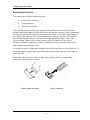
Be sure to fasten screws securely with the right screwdriver. If a screw is not fully
fastened, it could come loose, creating a danger of a short circuit, which could cause
overheating, smoke or fire.
If you replace the battery pack or RTC battery, be sure to use only the same model
battery or an equivalent battery recommended by Toshiba. Installation of the wrong
battery can cause the battery to explode.
Satellite P300 Maintenance Manual (960-Q08)
3
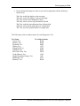
The manual is divided into the following parts:
Chapter 1
Hardware Overview describes the Satellite A300 system unit and each
FRU.
Chapter 2
Troubleshooting Procedures explains how to diagnose and resolve
FRU problems.
Chapter 3
Test and Diagnostics describes how to perform test and diagnostic
operations for maintenance service.
Chapter 4
Replacement Procedures describes the removal and replacement of the
FRUs.
Appendices
The appendices describe the following:
Handling the LCD Module
Board layout
Pin assignments
Keyboard scan/character codes
Key layout
Wiring diagrams
BIOS Rewrite Procedures
EC/KBC Rewrite Procedures
Reliability
Satellite P300 Maintenance Manual (960-Q08)
4
Conventions
This manual uses the following formats to describe, identify, and highlight terms and
operating procedures.
Acronyms
On the first appearance and whenever necessary for clarification acronyms are enclosed in
parentheses following their definition. For example:
Read Only Memory (ROM)
Keys
Keys are used in the text to describe many operations. The key top symbol as it appears on
the keyboard is printed in boldface type.
Key operation
Some operations require you to simultaneously use two or more keys. We identify such
operations by the key top symbols separated by a plus (+) sign. For example, Ctrl + Pause
(Break) means you must hold down Ctrl and at the same time press Pause (Break). If
three keys are used, hold down the first two and at the same time press the third.
User input
Text that you are instructed to type in is shown in the boldface type below:
DISKCOPY A: B:
The display
Text generated by the computer that appears on its display is presented in the typeface
below:
Format complete
System transferred
Satellite P300 Maintenance Manual (960-Q08)
5
Table of Contents
Chapter 1
Hardware Overview
1.1
Features ..........................................................................................................................1
1.2
System Block Diagram ..................................................................................................6
1.3
2.5-inch Hard Disk Drive.............................................................................................11
1.4
Optical Drive................................................................................................................12
1.4.1DVD-ROM & CD-R/RW Drive ....................................................................12
1.5
Keyboard......................................................................................................................18
1.6
TFT Color Display.......................................................................................................20
1.6.1 LCD Module with CCFL backlight ..............................................................20
1.6.2 CCFL Inverter Board ...................................................................................24
1.7
Power Supply ...............................................................................................................25
1.8
Batteries .......................................................................................................................26
1.8.1Main Battery ..................................................................................................26
1.8.2Battery Charging Control...............................................................................27
1.8.3RTC battery....................................................................................................28
1.9
AC Adapter ..................................................................................................................29
Chapter 2
Troubleshooting Procedures
2.1
Troubleshooting .............................................................................................................1
2.2
Troubleshooting Flowchart............................................................................................3
2.3
Power Supply Troubleshooting .....................................................................................8
2.4
Procedure 1
Power Status Check ...................................................................8
Procedure 2
Error Code Check ....................................................................10
Procedure 3
Connection Check....................................................................11
Procedure 4
Charging Check .......................................................................11
Procedure 5
Replacement Check ................................................................ 13
System Board Troubleshooting .................................................................................. 14
Satellite P300 Maintenance Manual (960-Q08)
6
2.5
2.6
2.7
2.8
Procedure 1
Message Check ....................................................................... 15
Procedure 2
Debugging Port Check............................................................ 17
Procedure 3
Diagnostic Test Program Execution Check ............................ 22
Procedure 4
Replacement Check ................................................................ 22
USB FDD Troubleshooting ........................................................................................ 24
Procedure 1
FDD Head Cleaning Check .................................................... 24
Procedure 2
Diagnostic Test Program Execution Check ............................ 25
Procedure 3
Connector Check and Replacement Check............................. 26
2.5” HDD Troubleshooting......................................................................................... 29
Procedure 1
Partition Check........................................................................ 29
Procedure 2
Message Check ....................................................................... 30
Procedure 3
Format Check.......................................................................... 31
Procedure 4
Diagnostic Test Program Execution Check ............................ 32
Procedure 5
Connector Check and Replacement Check............................. 33
Keyboard Troubleshooting ......................................................................................... 34
Procedure 1
Diagnostic Test Program Execution Check ............................ 34
Procedure 2
Connector Check and Replacement Check............................. 35
Touch pad Troubleshooting ........................................................................................ 36
Procedure 1
Diagnostic Test Program Execution Check ............................ 36
Procedure 2
Connector Check and Replacement Check............................. 37
Satellite P300 Maintenance Manual (960-Q08)
7
2.9
2.10
2.11
2.12
2.13
2.14
2.15
2.15
Display Troubleshooting..............................................................................................38
Procedure 1
External Monitor Check...........................................................38
Procedure 2
Diagnostic Test Program Execution Check .............................38
Procedure 3
Connector and Cable Check ....................................................39
Procedure 4
Replacement Check .................................................................40
Optical Disk Drive Troubleshooting............................................................................41
Procedure 1
Diagnostic Test Program Execution Check .............................41
Procedure 2
Connector Check and Replacement Check..............................41
Modem Troubleshooting..............................................................................................43
Procedure 1
Diagnostic Test Program Execution Check .............................43
Procedure 2
Connector Check and Replacement Check..............................43
LAN Troubleshooting..................................................................................................46
Procedure 1
Diagnostic Test Program Execution Check .............................46
Procedure 2
Connector Check and Replacement Check..............................46
Wireless LAN Troubleshooting...................................................................................47
Procedure 1
Transmitting-Receiving Check ................................................47
Procedure 2
Antennas' Connection Check ...................................................48
Procedure 3
Replacement Check .................................................................49
Sound Troubleshooting................................................................................................50
Procedure 1
Connector Check......................................................................50
Procedure 2
Replacement Check .................................................................51
Fingerprint Troubleshooting ........................................................................................52
Procedure 1
Diagnostic Test Program Execution Check .............................52
Procedure 2
Connector Check and Replacement Check.............................52
Bluetooth Troubleshooting ..........................................................................................53
Procedure 2
Connector Check and Replacement Check.............................53
Chapter 3 Test Program for Field
3.1
Tests and Diagnostics Software Overview ................................................................. 3-3
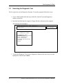
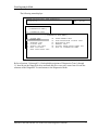
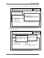
3.2
Executing the Diagnostic Test ................................................................................... 3-4
3.3
Subtest names............................................................................................................. 3-8
3.4
System Test.............................................................................................................. 3-11
Satellite P300 Maintenance Manual (960-Q08)
8
3.5
Memory Test............................................................................................................ 3-13
3.6
Keyboard Test.......................................................................................................... 3-16
3.7
Display Test ............................................................................................................. 3-19
3.8
Floppy Disk Test...................................................................................................... 3-34
3.9
Hard Disk Test ......................................................................................................... 3-36
3.10
Real Time Clock Test .............................................................................................. 3-39
3.11
Cache Memory Test................................................................................................. 3-41
3.12
High Resolution Display Test.................................................................................. 3-43
3.13
Multimedia Test ....................................................................................................... 3-49
3.14
MEMORY2 Test...................................................................................................... 3-50
3.15
Error Codes and Error Status Names ....................................................................... 3-52
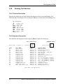
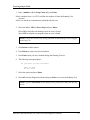
3.16
Running Test............................................................................................................ 3-54
3.17
DMI INFORMATION............................................................................................. 3-55
3.18
3.17.1
Check DMI Information………………………………………… 3-55
3.17.2
Write DMI Information……………………………………………3-55
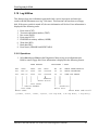
Log Utilities ............................................................................................................. 3-57
3.18.1...... Operations…………………………………………………………3-57
3.19
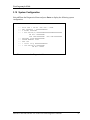
System Configuration .............................................................................................. 3-59
3.20
Running Test Edit Item............................................................................................ 3-60
3.20.1...... Function Description………………………………………………3-60
3.20.2
3.21
Operation Description……………………………………………3-60
Common Tests an Operation ..................................................................................... 3-62
3.21.1...... How to operate a window …………………………………………3-62
3.21.2...... How to Stop the Test Program ……………………………………. 3-62
3.21.3........ Test Status Screen …………………………………………………3-62
3.21.4...... Test Stop Display……………………………………………………3-64
Satellite P300 Maintenance Manual (960-Q08)
9
3.21. 5 How to enter data ……………………………………………………3-64
Chapter 4
4.1
Replacement Procedures
Overview.................................................................................................................... 4-1
Safety Precautions................................................................................................ 4-2
Before You Begin ................................................................................................ 4-3
Disassembly Procedure........................................................................................ 4-4
Assembly Procedure ............................................................................................ 4-5
Tools and Equipment ........................................................................................... 4-5
Screw Tightening Torque .................................................................................... 4-6
Grip Color ............................................................................................................ 4-6
Screw Notation .................................................................................................... 4-7
4.2
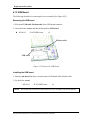
Battery pack ............................................................................................................... 4-8
4.3
PC card..................................................................................................................... 4-10
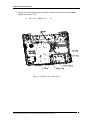
4.4
HDD(main HDD)..................................................................................................... 4-12
4.5
HDD(second HDD) ................................................................................................ 4-16
4.6
Wireless LAN card .................................................................................................. 4-16
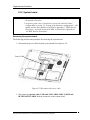
4.7
Memory module....................................................................................................... 4-23
4.8
Keyboard.................................................................................................................. 4-27
4.9
Optical disk drive..................................................................................................... 4-31
4.10
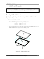
Display assembly ..................................................................................................... 4-33
4.11
Cover assembly........................................................................................................ 4-39
4.12
Touch pad................................................................................................................. 4-43
4.13
USB board................................................................................................................ 4-44
4.14
System board............................................................................................................4-46
4.15
CPU..........................................................................................................................4-49
4.16
LCD unit / FL inverter ............................................................................................. 4-52
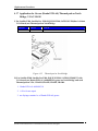
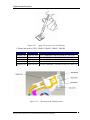
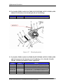
4.17
Application for grease(Denka FCR-AS) on North Bridge.………………………..4-57
Satellite P300 Maintenance Manual (960-Q08)
10
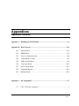
Appendices
Appendix A
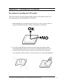
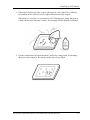
Handling the LCD Module ........................................................................... A-1
Appendix B
Board Layout ................................................................................................ B-1
Appendix C
Pin Assignments............................................................................................ C-1
Appendix D
Keyboard Scan/Character Codes .................................................................. D-1
Appendix E
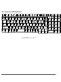
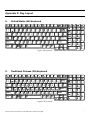
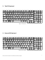
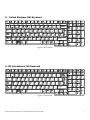
Key Layout.....................................................................................................E-1
Appendix F
Wiring Diagrams............................................................................................ F-1
Appendix G
BIOS Rewrite Procedures ............................................................................. G-1
Appendix H
EC/KBC Rewrite Procedures........................................................................ H-1
Appendix I
Reliability........................................................................................................I-1
Satellite P300 Maintenance Manual (960-Q08)
11
Satellite P300 Maintenance Manual (960-Q08)
12
Chapter 1
Hardware Overview
Satellite P300 and Satellite Pro P300 Maintenance Manual(960-Q08)
I-1
Chapter 1
Hardware Overview
Chapter 1
Contents (Intel Platform)
1.1
Features ..........................................................................................................................1
1.2
System Block Diagram ..................................................................................................5
1.3
2.5-inch Hard Disk Drive...............................................................................................9
1.4
Optical Drive (DVD Super Multi Drive) .....................................................................13
1.5
Keyboard......................................................................................................................16
1.6
TFT Color Display.......................................................................................................18
1.6.1
LCD Module with CCFL backlight .......................................................18
1.6.2
CCFL Inverter Board .............................................................................22
1.7
Power Supply ...............................................................................................................23
1.8
Batteries .......................................................................................................................24
1.9
1.8.1
Main Battery...........................................................................................24
1.8.2
Battery Charging Control .......................................................................25
1.8.3
RTC battery ............................................................................................26
AC Adapter ..................................................................................................................27
Figures
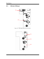
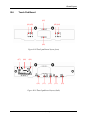
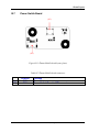
Figure 1-1
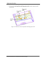
Front of the computer…………………………………………………………4
Figure 1-2
System block diagram for AMD Platform.........................................................5
Figure 1-3
2.5-inch HDD.....................................................................................................9
Figure 1-4
DVD Super Muti drive.....................................................................................13
Figure 1-5
Keyboard for US style .....................................................................................16
Figure 1-6
Keyboard for UK style.....................................................................................16
Figure 1-7
Keyboard for JP style.......................................................................................17
Figure 1-8
LCD module (LG-Philips) ..............................................................................18
Figure 1-9
LCD module (AUO) .......................................................................................19
Figure 1-10
LCD module (CMO).......................................................................................20
Figure 1-11
LCD module (SAMSUNG) ............................................................................21
Satellite P300 and Satellite Pro P300 Maintenance Manual(960-Q08)
I-2
Hardware Overview
Chapter 1
Tables
Table 1-1
2.5-inch HDD dimensions .................................................................................9
Table 1-2
2.5-inch HDD dimensions ...............................................................................10
Table 1-3
2.5-inch HDD specifications............................................................................11
Table 1-4
DVD Super Multi drive outline dimensions ....................................................13
Table 1-5
DVD Super Multi drive specifications ............................................................14
Table 1-6
LCD module specifications..............................................................................21
Table 1-7
FL inverter board specifications ......................................................................22
Table 1-8
Power supply output rating ..............................................................................23
Table 1-9
Battery specifications.......................................................................................24
Table 1-10
Time required for charges of main battery ......................................................25
Table 1-11
Data preservation time .....................................................................................25
Table 1-12
Time required for charges of RTC battery.......................................................26
Table 1-13
AC adapter specifications ................................................................................27
Satellite U300 and Satellite Pro U300 Maintenance Manual(960-Q08)
1-1
Chapter 1 Hardware Overview
Features
1.1
Features
The Satellite P300 Satellite Pro P300 (Intel Platform) series are 2 spindle PCs running
Intel® Core Duo Processor T8100 (800MHz) or higher
Intel® Core Duo Processor T9300 (800MHz) or higher.
Intel® Pentium Dual Processor T2330 or higher.
Intel® Celeron 540 Processor or higher.
Intel® Core™2 Duo Processor (667MHz) T5450 or higher.
The features are listed below.
θ Microprocessor
Microprocessor that is used will be different by the model.
It supports processors as follows:
Intel Core2 Duo Processor
FSB : 667 MHz
T5550(1.83GHz)
T5750(2.0GHz)
T5850(2.16GHz
FSB : 800MHz
T8100(2.10GHz)
T8300(2.40GHz)
T9300(2.5GHz)
T9500(2.6GHz)
Intel Pentium Dual
FSB :533GHz
T2330(1.6GHz)
T2370(1.73GHz)
T2390(1.86GHz)
Intel Celeron
FSB : 533 GHz
540(1.86GHz)
550(2.0GHz)
560(2.13GHz)
570(2.26GHz)
θ Memory
Two DDRII SO-DIMM (667MHz specification compliant) used can be up to 4GB
(but 2GB for GL960) which can be upgraded through Memory Module Slot.
Satellite P300 Maintenance Manual (960-Q08)
1
Chapter 1 Hardware Overview
Maximum upgradeable system memory may depend on the model
θ VRAM
Shared with System RAM for Intel GM965, PM965,GL960, GM965 +ATI
M82XT Graphic card:64MB,128MB,256MB.
θ HDD(First/Second Hard Drive – SATA)
160GB, 200GB, 250GB, 300GB, internal drives. 2.5 inch x 9.5mm height.
θ USB FDD (Option)
Toshiba external USB FDD for option
θ Display
LCD
17-inch, 1,440 (H) x 900 (V) WXGA+ 262,144 colors + CCFL, High-brightness,
amorphous silicon TFT color display..
CRT
Supported via a RGB connector.
θ Keyboard
Toshiba keyboard module has (104/105/109 keys) with three LEDs design, Support
Windows keys & Application keys. Multi-langue support.
θ New Dummy card slot
The new card slot (dummy card) accommodates one 5mm Type II card. The slot
support 16-bit PC cards.
θ Optical devices
A DVD Super Multi drive is equipped.
θ Battery
The RTC battery is equipped inside the computer.
SatelliteP300 Maintenance Manual (960-Q08)
2
Chapter 1 Hardware Overview
It is good with no external power source for 1month on average.
The main battery is a detachable lithium ion battery.
6 cell Li-Ion 10.8v/4000mAh
9 cell Li-Ion 10.8v/6000mAh
θ USB (Universal Serial Bus)
3 USB ports are provided. The ports comply with the USB2.0 standard, which
enables data transfer speeds 40 times faster than USB1.1 standard. USB1.1 is also
supported.
θ Sound system
Internal stereo speaker, Internal MIC (Option) external monaural microphone
connector, stereo headphone connector.
θ Wireless LAN
The wireless LAN is equipped on the mini card slot.
θ LAN/MODEM
Connectors for LAN and Modem are separately mounted.
θ 1394
One 1394 port is equipped.
θ Multiple Digital Media Card Slot
XD/MS/MS pro/SD/MMC are supported
θ Bluetooth
USB Bluetooth Module standard Ver 2.1 & EDR(Enhanced Data Rate) equipped
θ Security
Kensington Lock,
Fingerprint –Enhanced Lock is also equipped.
θ HDD Password
Satellite P300 Maintenance Manual (960-Q08)
3
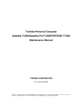
Chapter 1 Hardware Overview
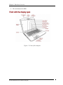
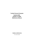
θ 3D Accelerometer for HDD
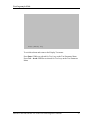
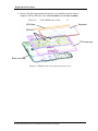
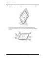
Figure 1-1 Front of the computer
SatelliteP300 Maintenance Manual (960-Q08)
4
Chapter 1 Hardware Overview
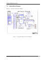
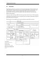
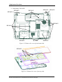
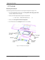
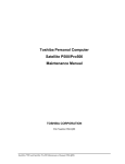
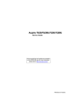
1.2
System Block Diagram
Figure 1-2 shows the system block diagram.
Figure 1-2 System block diagram for Intel Platform
Satellite P300 Maintenance Manual (960-Q08)
5
Chapter 1 Hardware Overview
The PC contains the following components.
θ CPU
Intel Core2 Duo Processor
FSB : 667 MHz
T5550(1.83GHz)
T5750(2.0GHz)
T5850(2.16GHz
FSB : 800MHz
T8100(2.10GHz)
T8300(2.40GHz)
T9300(2.5GHz)
T9500(2.6GHz)
Intel Pentium Dual
FSB :533GHz
T2330(1.6GHz)
T2370(1.73GHz)
T2390(1.86GHz)
Intel Celeron
FSB : 533 GHz
540(1.86GHz)
550(2.0GHz)
560(2.13GHz)
570(2.26GHz)
θ Memory
Two memory slots capable of accepting DDRII-SDRAM 512MB,1GB or 2GB
memory modules for a maximum of 4GB(2GB for GL960).
•
•
200-pin SO-DIMM
1.8V operation
θ BIOS ROM (Flash memory)
•
8Mbit
θ Chipset (Santa Rosa Platform)
This gate array has the following elements and functions.
SatelliteP300 Maintenance Manual (960-Q08)
6
Chapter 1 Hardware Overview
•
North Bridge (Intel PM965,GM965/GL960)
−
−
−
−
•
Celeron processor System Bus support
DRAM Controller : DDRII 533/667/800 support
DMI
1299-ball 35 x 35mm Mirco FC-BGA Package
South Bridge (Intel 82801HBM ICH8-M)
−
−
−
−
−
−
−
−
−
−
−
−
−
−
−
−
Direct Media Interface (DMI)
PCI Express
Serial ATA (SATA) Controller
PCI Interface
Low Pin count (LPC) interface
Serial Peripheral Interface (SPI)
DMA controller
Advanced Programmable Interrupt Controller (APIC)
USB Controllers
Gigabit Ethernet Controller
RTC
GPIO
Enhanced Power Management
SMBus 2.0
High Definition Audio Controller
676-pin 31mmx31mm mBGA Package
θ Other main system chips
• Clock Generator (ICS951462AGLFT)
• EC/KBC (Support CIR : Winbond WPCE775CA0DG)
• EC/KBC (No Support CIR : Winbond WPCE775LA0DG)
• HD Audio (CONEXANT CX20561-12Z)
• Audio AMP (GMT G1441R51U)
• 1394/Card Reader controller (O2 OZ129TN)
• 10/100 LAN controller (Marvell 88E8040T-A0-NNC1C000)
• GIGA LAN controller (Marvell 88E8072-B1-NNC1C000)
θ Mini Card
Wireless LAN card (BTO)
5.4 GHz DSSS/OFDM LAN card is equipped. Conformity with IEEE 802.11b/g,
IEEE 802.11 a/g/n and IEEE 802.11a/b/g..
Satellite P300 Maintenance Manual (960-Q08)
7
Chapter 1 Hardware Overview
θ MODEM (Conexant x 1)
Supported by on board Modem + DAA daughter card.
Data and FAX transmission is available.
Supports ITU-TV.90.
The transfer speed of data receiving is 56kbps, of data sending is 33.6kbps and of
FAX is 14.4kbps. Actual speed depends on the quality of the line used.
Connected to telephone line through RJ11 MOD
SatelliteP300 Maintenance Manual (960-Q08)
8
Chapter 1 Hardware Overview
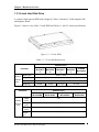
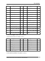
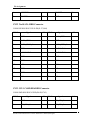
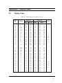
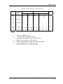
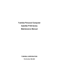
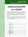
1.3 2.5-inch Hard Disk Drive
A compact, high-capacity HDD with a height of 9.5mm. Contains a 2.5-inch magnetic disk
and magnetic heads.
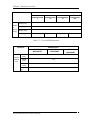
Figure 1-3 shows a view of the 2.5-inch HDD and Tables 1-1 and 1-2 list the specifications.
Figure 1-3 2.5-inch HDD
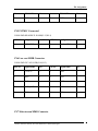
Table 1-1 2.5-inch HDD dimensions
Standard value
Parameter
Outline
dimens
ions
TOSHIBA
MK1246GS
X
TOSHIBA
MK1646GS
X
TOSHIBA
MK2046GS
X
Width (mm)
69.85 +/- 0.25
Height (mm)
9.5
Depth (mm)
100.2 +/- 0.25
Weight (g)
97/98
Parameter
97/98
TOSHIBA
MK2546GS
X
101//102
TOSHIBA
MK3252GSX
101//102
Standard value
FUJITSU
MHY2120BH
FUJITSU
MHY2160BH
FUJITSU
MHY2200BH
100
Outline
Width
(mm)
dimensi
ons
Height
(mm)
9.5
Depth
(mm)
70
Weight
(g)
Satellite P300 Maintenance Manual (960-Q08)
FUJITSU
MHY2250BH
101(Max)
9
Chapter 1 Hardware Overview
Parameter
Standard value
HITACHI
HTS542512k9SA0
0
Outlin
e
dimen
sions
HITACHI
HTS542516k9SA
00
HITACHI
HTS542520k9SA
00
Width (mm)
69.85 +/- 0.25
Height (mm)
9.5
Depth (mm)
100.2 +/- 0.25
Weight (g)
95 (max.)
95 (max.)
102 (max.)
HITACHI
HTS542525k9S
A00
102 (max.)
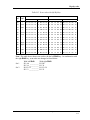
Table 1-2 2.5-inch HDD dimensions
Parameter
Standard value
FUJITSU
MHX2250BT
FUJITSU
MHX2300BT
100
Outline
Width
(mm)
dimensi
ons
Height
(mm)
12.5
Depth
(mm)
70.0
Weight
(g)
SatelliteP300 Maintenance Manual (960-Q08)
FUJITSU
MHZ2400BT
101(Max)
10
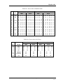
Chapter 1 Hardware Overview
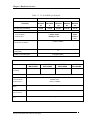
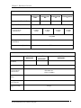
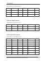
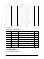
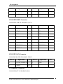
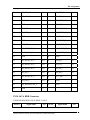
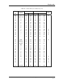
Table 1-3 2.5-inch HDD specifications
Specification
Parameter
Storage size (formatted)
TOSHIBA
TOSHIBA
MK1246G
SX
TOSHIBA
MK1646GS
X
TOSHIBA
MK2046G
SX
TOSHIBA
MK2546G
SX
MK3252G
SX
120GB
160GB
200GB
250 GB
320GB
Speed (RPM)
Data transfer Rate
- To/From Media
- T0/From Host
5,400
730Mbits Media
300MBytes Host
794Mbits
Media
3GBytes
Host
1.5Gbps(150MB/s)
bus transfer rate (MB/s)
Average random seek time
(read) (ms)
12
Power-on-to-ready (sec)
3.5(typ)/9.5(Max)
Specification
Parameter
Storage size
(formatted)
FUJITSU
MHY2120BH
80GB
Speed (RPM)
Data transfer Rate
- To/From Media
- T0/From Host
bus transfer rate
(MB/s)
Average random seek
time (read) (ms)
Power-on-to-ready
(sec)
Satellite P300 Maintenance Manual (960-Q08)
FUJITSU
MHY2160BH
120GB
FUJITSU
MHY2200BH
200GB
FUJITSU
MHY2250BH
250GB
5,400
84.6MB/s Max.
1.5Gbps (150MB/s)
1.5Gbps(150MB/s)
12.0ms/14.0ms
4.0 (typ.)
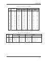
11
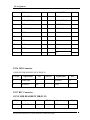
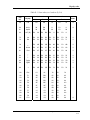
Chapter 1 Hardware Overview
Specification
Parameter
HITACHI
HTS542512k9
SA00
HITACHI
HTS542516k9S
A00
HITACHI
HTS542520k9SA
00
HITACHI
HTS542525k9SA0
0
120GB
160GB
200GB
250GB
Storage size (formatted)
Speed (RPM)
5,400
Data transfer Rate
- To/From Media
- T0/From Host
65.5MB/s
1.5Gbps
65.5MB/s
1.5Gbps
65.5MB/s
1.5Gbps
65.5MB/s
1.5Gbps
bus transfer rate (MB/s)
150 (MB/s
Average random seek time
(read) (ms)
11
Power-on-to-ready (sec)
3.5 sec
Specification
Parameter
Storage size
(formatted)
FUJITSU
MHX2250BT
250GB
Speed (RPM)
Data transfer Rate
- To/From Media
- T0/From Host
bus transfer rate
(MB/s)
Average random seek
time (read) (ms)
Power-on-to-ready
(sec)
SatelliteP300 Maintenance Manual (960-Q08)
FUJITSU
FUJITSU
MHZ2400BT
MHX2300BT
300GB
400GB
4,200
60.8MB/s Max.
1.5Gbps (150MB/s)
1.5Gbps (150MB/s)
12.0ms/14.0ms
4.0 (typ)
12
Chapter 1 Hardware Overview
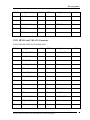
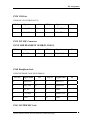
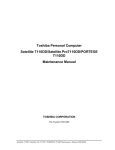
1.4 Optical drive (DVD Super Multi Drive)
The DVD Super Multi drive accommodates either 12 cm (4.72-inch) or 8 cm (3.15-inch)
CD/DVD-ROM, CD-R/RW, DVD±R/±RW and DVD-RAM. It is a high-performance drive
that reads DVD-ROM at maximum 8-speed and CD at maximum 24-speed. Write speed of
DVD±R/±RW and DVD-RAM is different depending on the drive.
The DVD Super Multi drive is shown in Figure 1-4. The dimensions and specifications of the
DVD Super Multi drive are described in Table 1-4, Table 1-5.
Figure 1-4 DVD Super Multi drive
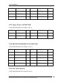
Table 1-4 DVD Super Multi drive outline dimensions
Parameter
Outline
dimension
Standard Value
TST
TST
PNR
PNR
Maker
TSL632H
TS-L632P
DVRKD08TBT
DVRKD08TBL
Width
(mm)
122.4
122.4
128
128
Height
(mm)
12.7
12.7
12.7
12.7
Depth
(mm)
126
126
134
134
Mass
(g)
104
104
176.2
176.2
Satellite P300 Maintenance Manual (960-Q08)
13
Chapter 1 Hardware Overview
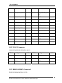
Table 1-5 DVD Super Multi drive specifications (1/4)
Drive Specification
Parameter
Read (KB/s)
TST
TST
PNR
PNR
TS-L632H
TS-L632P
DVR-KD08TBT
DVR-KD08TBL
CD-ROM
3600 KB/s
CD-R
3600 KB/s
CD-RW
3600 KB/s
DVD-ROM(L)
10800 KB/s
DVD+/-R
Dual8100KB/s
DVD-RAM
6750 KB/s
CD-ROM
3600 KB/s
CD-R
3600 KB/s
CD-RW
3600 KB/s
DVD-ROM(SL)
10800 KB/s
DVD+/-R Dual
8100 KB/s
DVD-RAM
6750 KB/s
CDInner 1,545
Outer 3,600
(10.3-24XCAV mode
over16 Block
Transfer)DVD(single
Layer)Inner 4,455
Outer 10,800
(3.3X-8X CAV mode
Over16 Block
Transfer)DVD-RM
Inner 4,155
Outer 6,925
CDInner 1,545
Outer 3,600
(10.3-24X CAV mode
over16 Block Transfer)
DVD(single Layer)Inner
4,455
Outer 10,800
(3.3X-8X CAV mode
Over16 Block
Transfer)DVD-RAM
Inner 4,155
Outer 6,925
(3X-5XZone-CLV mode
Over16 Block Transfer)
(3X-5XZone-CLV
mode Over16 Block
Transfer)
Data transfer
speed
Write
ATAPI
interface
(MB/s)
CD-ROM
Access time
(ms) (Random)
CD-R
3600 KB/s
MS CD-RW
600 KB/s
HS CD-RW
1500 KB/s
US CD-RW
2400 KB/s
US+ CD-RW
Not Support
DVD+R/-R
10800 KB/s
CD-R
3600 KB/s
MS CD-RW
600 KB/s
HS CD-RW
1500 KB/s
US CD-RW
2400 KB/s
US+ CD-RW
Not Support
DVD+R/-R
10800 KB/s
CDInner 1,500
Outer 3,600
(24x Zone-CLV CD-R
write)DVD-RInner
2,700Outer 10,800
(8X
Zone-CLV
write)DVD+R
Inner
3,240Outer
10,800(8X Zone-CLV
write)DVD-RAM
Inner
4,155Outer
6,925
(3X-5X
Zone-CLV
write)
MAX
33.2MB/s
MAX
33.2MB/s
16.6(PIO
Mode4/MultiwordDM
A Mode2)
33.3(UltraDMAMode2
130 ms
130 ms
DVD-ROM
SatelliteP300 Maintenance Manual (960-Q08)
130 ms
130 ms
CDInner 1,500
Outer 3,600
(24x Zone-CLV
CD-R write)
DVD-R
Inner 2,700
Outer 10,800
(8X Zone-CLV write)
DVD+R
Inner 3,240
Outer 10,800
(8X Zone-CLV write)
DVD-RAM
Inner 4,155
Outer 6,925
(3X-5X Zone-CLV write)
16.6(PIO
Mode4/MultiwordDMA
Mode2)
33.3(UltraDMA Mode2)
Ave.140(CD-ROM
Mode1Disc is used)
Ave.140(CD-ROM
Mode 1 Disc is used)
Ave.150
(DVD-ROM
Single
Layer Disc is used)
Ave.150
(DVD-ROM Single
Layer Disc is use
14
Chapter 1 Hardware Overview
2M
Buffer memory
2M
2 Mbytes
2 Mbytes
CD
650MB CDROMR(Rad
Only)
80mm
CD(Horizontal
Mount only)
800/700/650
CDRecordable
(Read & Write)
700/650 MB
CD-Rewritable
(Read & Write)
700/650MB
High Speed
CD-Rewritable
(Read & Write)
700/650 MB
Ultra Speed
CD-Rewritable
(Read & Write)
Ultra+ Speed
CD-Rewritable
(Read Only)
650MB CDROMR(Read
Only)
80mm
CD(Horizontal
Mount only)
800/700/650
CDRecordable
(Read & Write)
700/650 MB
CD-Rewritable
(Read & Write)
700/650MB
High Speed
CD-Rewritable
(Read & Write)
700/650 MB
Ultra Speed
CD-Rewritable
(Read & Write)
Ultra+ Speed
CD-Rewritable
(Read Only)
CD-ROM Mode1
CD-ROM XA Mode2
(form1, form2)
Photo CD ( single and
multiple session)
Video CD
CD-DA
CD-Extra
Mixed-CD
CD-Text
CD-R
CD-RW(Supports
AM2)
HSCD-RW(Supports
AM2)
USCD-RW(Supports
AM2)
US+CD-RW(Supports
AM2)(*Read only)
CD-ROM Mode1
CD-ROM XA Mode2
(form1, form2)
Photo CD ( single and
multiple session)
Video CD
CD-DA
CD-Extra
Mixed-CD
CD-Text
CD-R
CD-RW(Supports AM2)
HSCD-RW(Supports
AM2)
USCD-RW(Supports
AM2)
US+CD-RW(Supports
AM2)(*Read only)
5/9/10/18
G DVDSingle/Dual
(PTP, OTP)
(Read Only)
4.7G DVD+R/RW (Read &
Write)
DVD+-R Dual
(Read & Write)
DVD-RAM
(Read & Write)
80mm DVD
DVD (DVD-5; Single
layer, Single side
4.7Gbytes)
DVD (DVD-9; Dual
layer, Single
DVD (DVD-5; Single
layer, Single side
4.7Gbytes)
DVD (DVD-9; Dual
layer, Single
DVD
5/9/10/18 G
DVDSingle/Dual
(PTP, OTP)
(Read Only)
4.7G DVD+R/RW (Read &
Write)
DVD+-R Dual
(Read & Write)
DVD-RAM
(Read
&Write)80mm
DVD
Supported disk format
Satellite P300 Maintenance Manual (960-Q08)
15
Chapter 1 Hardware Overview
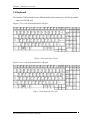
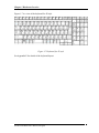
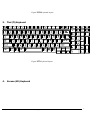
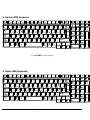
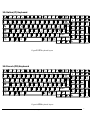
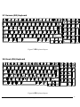
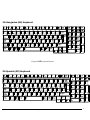
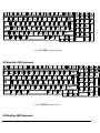
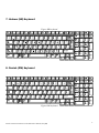
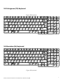
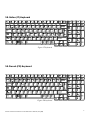
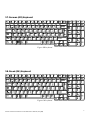
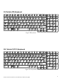
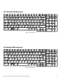
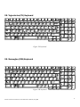
1.5 Keyboard
The Satellite P300 keyboard has two different kinds of placement, one is for JP style and the
other is for US/UK style
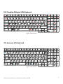
Figure 1-5 is a view of the keyboard for US style
Figure 1-5 Keyboard for US style
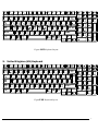
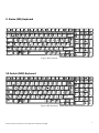
Figure 1-6 is a view of the keyboard for UK style.
Figure 1-6 Keyboard for UK style
SatelliteP300 Maintenance Manual (960-Q08)
16
Chapter 1 Hardware Overview
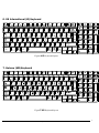
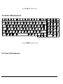
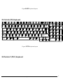
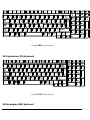
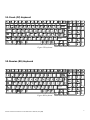
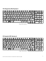
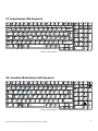
Figure 1-7 is a view of the keyboard for JP style.
Figure 1-7 Keyboard for JP style
See Appendix E for details of the keyboard layout.
Satellite P300 Maintenance Manual (960-Q08)
17
Chapter 1 Hardware Overview
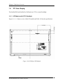
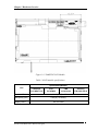
1.6
TFT Color Display
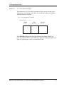
The SatelliteP300 and Satellite Pro 300 Panel use CCFL to control backlight.
1.6.1 LCD Module with CCFL Backlight
Figure 1-8 ~ 1-11 shows a view of the LCD module and Table 1-8 lists the specifications.
Figure 1-8 LG-Philips LCD Module
SatelliteP300 Maintenance Manual (960-Q08)
18
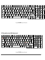
Chapter 1 Hardware Overview
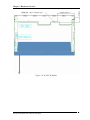
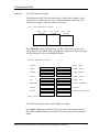
Figure 1-9 AUO LCD Module
Satellite P300 Maintenance Manual (960-Q08)
19
Chapter 1 Hardware Overview
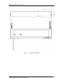
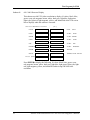
Figure 1-10 CMO LCD Module
SatelliteP300 Maintenance Manual (960-Q08)
20
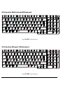
Chapter 1 Hardware Overview
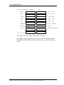
Figure 1-11 SAMSUNG LCD Module
Table 1-6 LCD module specifications
Specifications(WXGA+)
Item
LG-Philips
AUO
CMO
Samsung
LP171WP4-TLN1
B170PW06
N170C2-L02
LTN170X2-L02-S
Number of Dots
Dot spacing (mm)
Display Colors
Satellite P300 Maintenance Manual (960-Q08)
1,440 x 3(R,G,B) x 900
0.255(H)× 0.2555(V)
262,144 colors
21
Chapter 1 Hardware Overview
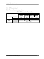
1.6.2 CCFL Inverter Board
Table 1-7 lists the FL inverter board specifications.
Table 1-7 FL inverter board specifications
Specifications
Foxconn
T18I095.00
Delta
DAC-08N035
AF
SUMIDA
TWS-449-308
TDK
TBD485NR
Voltage (V)
8~20
8~20
8~20
8~20
Power (W)
7.5W
7.5W
7.5W
7.5W
612~945
612~945
612~945
612~945
Item
Input
Voltage (Vrms)
Output
Current
(f=55KHz)(mArms)
SatelliteP300 Maintenance Manual (960-Q08)
2.3±0.4 ~ 6.5±0.3
22
Chapter 1 Hardware Overview
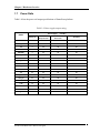
1.7
Power Rails
Table 1-8 lists the power rail output specifications of Santa Rosa platform.
Table 1-8 Power supply output rating
Power supply (Yes/No)
Name
Voltage [V]
Power OFF
Suspend mode
Power OFF
Boot mode
No Battery
+5VPCU
5
Yes
Yes
No
+5V_S5
5
Yes
No
No
+5V
5
No
No
No
+5VSATA
5
No
No
No
USBPWR1
5
No
No
No
+5V_TP
5
No
No
No
VCCRTC
3.3
Yes
Yes
Yes
TH_FAN_POWER
3.1~5
No
No
No
+3VPCU
3.3
Yes
Yes
No
+3V_S5
3.3
Yes
No
No
+3VSUS
3.3
Yes
No
No
+3V
3.3
No
No
No
CCD_POWER
3.3
No
No
No
VCC_XD
3.3
No
No
No
+1.8VSUS
1.8
Yes
No
No
+1.5V
1.5
No
No
No
+1.25V
1.25
No
No
No
+1.05V
1.05
No
No
No
VCC_CORE
0.55~1.575
No
No
No
Satellite P300 Maintenance Manual (960-Q08)
23
Chapter 1 Hardware Overview
1.8
Batteries
The PC has the following two batteries.
θ Main battery
θ Real time clock (RTC) battery
Table 1-9 lists the specifications for these two batteries.
Table 1-9 Battery specifications
Battery Name
Battery Element
Sanyo
6 cell
Panasonic
Main battery
Lithium ion
6 cell
Sanyo
9 cell
Real time clock
(RTC) battery
Panasonic
ML1220/F1BEMOLEX-58ZL1
Lithium ion
Output Voltage
Capacity
10.8v
4000mAh
10.8v
4000mAh
10.8v
6000mAh
3V
17mAh
1.8.1 Main Battery
The main battery is the primary power supply for the computer when the AC adapter is not
connected. In Standby, the main battery maintains the current status of the computer.
SatelliteP300 Maintenance Manual (960-Q08)
24
Chapter 1 Hardware Overview
1.8.2 Battery Charging Control
Battery charging is controlled by a power supply microprocessor. The power supply
microprocessor controls power supply and detects a full charge when the AC adaptor and
battery are connected to the computer.
θ Battery Charge
When the AC adapter is connected, normal charging is used while the system is
turned on and quick charge is used while the system is turned off. Refer to the
following Table 1-10.
Table 1-10 Time required for charges of main battery
Condition
Charging Time
Power On Charge
About 12 hours-
Power Off Charge
About 4 hours
Charge is stopped in the following cases.
1. The main battery is fully charged
2. The main battery is removed
3. Main battery or AC adapter voltage is abnormal
4. Charging current is abnormal
θ Data preservation time
When turning off the power in being charged fully, the preservation time is as
following Table 1-11.
Table 1-11 Data preservation time
Condition
Standby
Hibernation
Battery 3 cell
Pack
6 cell
9 cell
preservation time
About 3 days
About 1 month
Approximately 1.5 days(sleep mode)
Approximately 3 days(sleep mode)
Approximately 5 days(sleep mode)
Approximately 1 month(shutdown mode,All type of battery pack
Satellite P300 Maintenance Manual (960-Q08)
25
Chapter 1 Hardware Overview
1.8.3 RTC Battery
The RTC battery provides the power supply to maintain the date, time, and other system
information in memory.
Table 1-12 lists the Time required for charges of RTC battery and data preservation time.
Table 1-12 Time required for charges of RTC battery
Condition
Time
Power ON (Lights Power LED)
About 24 hours
Data preservation tome (Full-charged)
About a month
SatelliteP300 Maintenance Manual (960-Q08)
26
Chapter 1 Hardware Overview
1.9
AC Adapter
The AC adapter is used to charge the battery.
Table 1-13 lists the AC adapter specifications.
Table 1-13 AC adapter specifications
Parameter
With Led
Power
Specification
DELTA/ LITE-ON
DELTA/ LITE-ON
DELTA/ LITE-ON
75W
90W
120W
Input voltage
AC 100V/240V
Input frequency
50Hz/60Hz
Input current
≦1.5A
Output voltage
DC 19V
Output current
3.95A
Satellite P300 Maintenance Manual (960-Q08)
4.74A
6.3A
27
Chapter 2
Troubleshooting Procedures
Chapter 2
Contents
2.1
Troubleshooting ............................................................................................................ 1
2.2
Troubleshooting Flowchart........................................................................................... 3
2.3
Power Supply Troubleshooting..................................................................................... 8
2.4
2.5
Procedure 1
Power Status Check .................................................................. 8
Procedure 2
Error Code Check ................................................................... 10
Procedure 3
Connection Check................................................................... 12
Procedure 4
Charging Check ...................................................................... 12
Procedure 5
Replacement Check ................................................................ 14
System Board Troubleshooting................................................................................... 15
Procedure 1
Message Check ....................................................................... 16
Procedure 2
Debugging Port Check............................................................ 18
Procedure 3
Diagnostic Test Program Execution Check ............................ 23
Procedure 4
Replacement Check ................................................................ 23
USB FDD Troubleshooting ........................................................................................ 24
Procedure 1
FDD Head Cleaning Check .................................................... 24
Procedure 2
Diagnostic Test Program Execution Check ............................ 25
Procedure 3
Connector Check and Replacement Check............................. 26
[CONFIDENTIAL]
2-1
2.6
2.7
2.8
2.9
2.10
2.11
2.12
2.13
2.14
2.5” HDD Troubleshooting......................................................................................... 28
Procedure 1
Partition Check........................................................................ 29
Procedure 2
Message Check ....................................................................... 29
Procedure 3
Format Check.......................................................................... 30
Procedure 4
Diagnostic Test Program Execution Check ............................ 31
Procedure 5
Connector Check and Replacement Check............................. 32
Keyboard Troubleshooting ......................................................................................... 33
Procedure 1
Diagnostic Test Program Execution Check ............................ 33
Procedure 2
Connector and Replacement Check ....................................... 34
Touch pad Troubleshooting ........................................................................................ 35
Procedure 1
Diagnostic Test Program Execution Check ............................ 35
Procedure 2
Connector Check and Replacement Check............................. 36
Display Troubleshooting............................................................................................. 37
Procedure 1
External Monitor Check.......................................................... 37
Procedure 2
Diagnostic Test Program Execution Check ............................ 37
Procedure 3
Connector and Cable Check.................................................... 38
Procedure 4
Replacement Check ................................................................ 39
Optical Disk Drive Troubleshooting........................................................................... 40
Procedure 1
Diagnostic Test Program Execution Check ............................ 40
Procedure 2
Connector Check and Replacement Check............................. 40
Modem Troubleshooting............................................................................................. 42
Procedure 1
Diagnostic Test Program Execution Check ............................ 42
Procedure 2
Connector Check and Replacement Check............................. 42
LAN Troubleshooting................................................................................................. 44
Procedure 1
Diagnostic Test Program Execution Check ............................ 44
Procedure 2
Connector Check and Replacement Check............................. 45
Wireless LAN Troubleshooting.................................................................................. 46
Procedure 1
Transmitting-Receiving Check ............................................... 46
Procedure 2
Antennas' Connection Check .................................................. 47
Procedure 3
Replacement Check ................................................................ 48
Sound Troubleshooting............................................................................................... 49
Procedure 1
Connector Check..................................................................... 49
[CONFIDENTIAL]Satellite P300 and Satellite Pro P300 Maintenance Manual(960-Q08)
2-2
Procedure 2
2.15
2.16
Replacement Check................................................................. 50
Fingerprint Troubleshooting .................................................................................... 51
Procedure 1
Diagnostic Test Program Execution Check ............................ 51
Procedure 2
Connector Check and Replacement Check............................ 51
Bluetooth Troubleshooting ......................................................................................... 52
Procedure 1
Connector Check and Replacement Check............................ 52
Satellite P300 and Satellite Pro P300 Maintenance Manual(960-Q08)
2-3
2 Troubleshooting Procedures
2
2.1
Troubleshooting
Chapter 2 describes how to determine which Field Replaceable Unit (FRU) in the computer
is causing the computer to malfunction.
The FRUs covered are:
1. Power supply
6. Touch pad
11. Wireless LAN
2. System Board
7. Display
12. Sound
3. USB FDD
8. Optical Disk Drive
13, Finger Print Board
4. 2.5” HDD
9. Modem
14, Bluetooth
5. Keyboard
10. LAN
The Test Program operations are described in Chapter 3. Detailed replacement procedures are
described in Chapter 4.
NOTE: After replacing the system board or CPU, it is necessary to execute the subtest 01
initial configuration of the 3.3 Setting of the hardware configuration in Chapter
3. Also update with the latest BIOS as described in Appendix G “BIOS Rewrite
Procedures”
After replacing the LCD, update with the latest EC/KBC as described in
Appendix H “EC/KBC Rewrite Procedures” to set the SVP parameter.
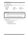
The implement for the Diagnostics procedures is referred to Chapter 3. Also, following
implements are necessary:
1. Phillips screwdrivers (For replacement procedures)
2. Implements for debugging port check
• Toshiba MS-DOS system FD
• RS-232C cross cable
• Test board with debug port test cable
• PC for displaying debug port test result
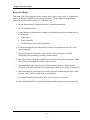
Satellite P300 and Satellite Pro P300 Maintenance Manual (960-Q08)
1
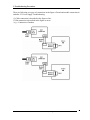
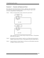
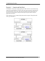
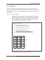
2 Troubleshooting Procedures
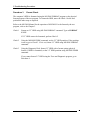
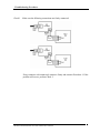
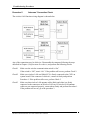
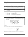
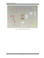
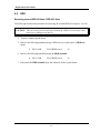
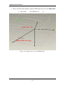
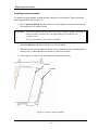
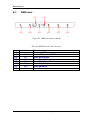
There are following two types of connections in the figure of board and module connection in
and after 2.3 Power Supply Troubleshooting.
(1) Cable connection is described in the figure as line.
(2) Pin connection is described in the figure as arrow.
<e.g.> Connection of modem
Satellite P300 and Satellite Pro P300 Maintenance Manual (960-Q08)
2
2 Troubleshooting Procedures
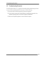
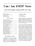
2.2
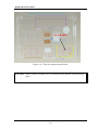
Troubleshooting Flowchart
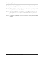
Use the flowchart in Figure 2-1 as a guide for determining which troubleshooting procedures
to execute. Before going through the flowchart steps, verify the following:
Ask him or her to enter the password if a password is registered.
Verify with the customer that Toshiba Windows is installed on the hard disk. NonWindows operating systems can cause the computer to malfunction.
Make sure all optional equipment is removed from the computer.
Satellite P300 and Satellite Pro P300 Maintenance Manual (960-Q08)
3
2 Troubleshooting Procedures
Figure 2-1 Troubleshooting flowchart (1/2)
Satellite P300 and Satellite Pro P300 Maintenance Manual (960-Q08)
4
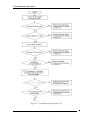
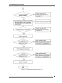
2 Troubleshooting Procedures
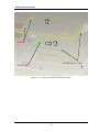
Figure 2-1 Troubleshooting flowchart (2/2)
Satellite P300 and Satellite Pro P300 Maintenance Manual (960-Q08)
5
2 Troubleshooting Procedures
If the diagnostics program cannot detect an error, the problem may be intermittent. The Test
program should be executed several times to isolate the problem. Check the Log Utilities
function to confirm which diagnostic test detected an error(s), and then perform the
appropriate troubleshooting procedures as follows:
1. If an error is detected on the system test, memory test, display test, CD-ROM/DVDROM test, expansion test, real timer test, sound test or Modem/LAN/Bluetooth
/IEEE1394 test, perform the System Board Troubleshooting Procedures in Section 2.4.
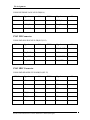
2. If an error is detected on the floppy disk test, perform the USB FDD Troubleshooting
Procedures in Section 2.5.
3. If an error is detected on the hard disk test, perform the HDD Troubleshooting
Procedures in Section 2.6.
4. If an error is found on the keyboard test (DIAGNOSTICS TEST) and pressed key
display test (ONLY ONE TEST), perform the Keyboard Troubleshooting Procedures
in Section 2.7.
5. If an error is found on the touch pad test (ONLY ONE TEST), perform the touch pad
Troubleshooting Procedures in Section 2.8.
6. If an error is detected on the display test, perform the Display Troubleshooting
Procedures in Section 2.9.
7. If an error is detected on the CD-ROM/DVD-ROM test, perform the Optical Disk
Drive Troubleshooting Procedures in Section 2.10.
8. If an error is detected on the modem test, perform the Modem Troubleshooting
Procedures in Section 2.11.
9. If an error is detected on the LAN test, perform the LAN Troubleshooting Procedures
in Section 2.12.
10. If an error is detected on the wireless LAN test, perform the Wireless LAN
Troubleshooting Procedures in Section 2.13.
11. If an error is detected on the sound test, perform the Sound Troubleshooting
Procedures in Section 2.14.
12. If an error is detected on the VGA daughter card test, perform the VGA
Troubleshooting Procedures in Section 2.15.
13. If an error is detected on the fingerprint test, perform the fingerprint Troubleshooting
Procedures in Section 2.16.
14. If an error is detected on the Bluetooth test, perform the Bluetooth Troubleshooting
Satellite P300 and Satellite Pro P300 Maintenance Manual (960-Q08)
6
2 Troubleshooting Procedures
Procedures in Section 2.17.
Satellite P300 and Satellite Pro P300 Maintenance Manual (960-Q08)
7
2 Troubleshooting Procedures
2.3
Power Supply Troubleshooting
The power supply controller controls many functions and components. To determine if the
power supply is functioning properly, start with Procedure 1 and continue with the other
Procedures as instructed. The procedures described in this section are:
Procedure 1: Power Status Check
Procedure 2: Error Code Check
Procedure 3: Connection Check
Procedure 4: Charging Check
Procedure 5: Replacement Check
Procedure 1
Power Status Check
The following LED indicates the power supply status:
Battery LED
DC IN LED
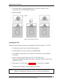
The Power Supply control displays the power supply status with the Battery LED and the DC
IN LED as listed in the tables below.
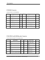
Table 2-1 Battery icon(Low cost)
Battery icon
Power supply status
Lights orange
Battery is charged and the external DC is input. It has no
relation with ON/OFF of the system power.
Lights white(Green)
Battery is fully charged and the external DC is input. It has
no relation with ON/OFF of the system power.
Blinks orange
(even intervals)
The battery level is low while the system power is ON.
Blinks orange once
(at being switched on)
The system is driven by only a battery and the battery level
is low.
Doesn’t light
Any condition other than those above.
Satellite P300 and Satellite Pro P300 Maintenance Manual (960-Q08)
8
2 Troubleshooting Procedures
Table 2-2 DC IN icon(Low cost)
DC IN icon
Power supply status
Lights white(Green)
DC power is being supplied from the AC adapter.
Blinks white(Green)
Power supply malfunction*1
Doesn’t light
Any condition other than those above.
*1 When the power supply controller detects a malfunction, the DC IN icon blinks
white. It shows an error code.
When the icon is blinking, perform the following procedure.
1.
Remove the battery pack and the AC adapter.
2.
Re-attach the battery pack and the AC adapter.
If the icon is still blinking after the operation above, check the followings:
Check 1 If the DC IN icon blinks white, go to Procedure 2.
Check 2 If the DC IN icon does not light, go to Procedure 3.
Check 3 If the battery icon does not light white or red, go to Procedure 4.
NOTE: Use a supplied AC adapter.
Satellite P300 and Satellite Pro P300 Maintenance Manual (960-Q08)
9
2 Troubleshooting Procedures
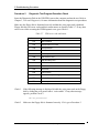
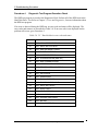
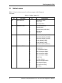
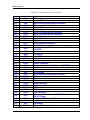
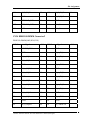
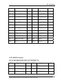
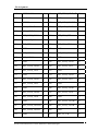
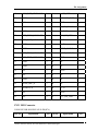
Procedure 2. Error Code Check
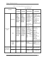
The following table lists the error codes and error status names for the Diagnostic Tests.
Table 2-3 Error codes and error status names (1/2)
Device Name
Error Code
Error Status Name
(Common)
FF
Data Compare Error
Memory
02
Protected Mode Not Changed
??
Other Error
01
Bad Command Error
02
Address Mark Not Found
03
Write Protected
04
Record Not Found
06
Media Change Line Error
08
DMA Overrun Error
09
DMA Boundary Error
0C
Select Media Error
10
CRC Error
20
FDC Error
40
Seek Error
80
Time Out Error
??
Other Error
01
Bad Command Error
02
Bad Address Mark Error
04
Record Not Found
05
HDC Not Reset Error
07
Drive Not Initialized
09
DMA Boundary Error
0A
Bad Sector
0B
Bad Track Error
10
ECC Error
11
ECC Recover Enabled
20
HDC Error
40
Seek Error
80
Time Out Error
AA
Drive Not Ready
FDD
HDD
Satellite P300 and Satellite Pro P300 Maintenance Manual (960-Q08)
10
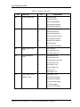
2 Troubleshooting Procedures
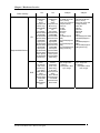
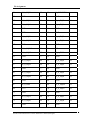
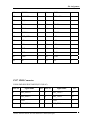
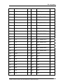
Table2 -3 Error codes and error status names (2/2)
Device Name
HDD
Cache Memory
Multimedia
Error Code
Error Status Name
BB
Undefined Error
CC
Write Fault
E0
Status Error
F0
No Sense Error
??
Other Error
02
Protect Mode Error
03
Caching Error
??
Other Error
01
Write Error
0F
Invalid Drive
15
Drive Not Ready
??
Other Error
NOTE: If error status name is Other Error , please reference the Error Code for error
information
Satellite P300 and Satellite Pro P300 Maintenance Manual (960-Q08)
11
2 Troubleshooting Procedures
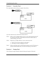
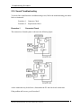
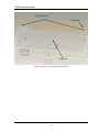
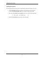
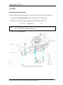
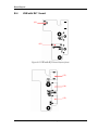
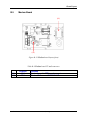
Procedure 3
Connection Check
The wiring diagram related to the power supply is shown below:
Any of the connectors may be disconnected. Perform Check 1.
Check 1
Make sure the AC adapter and the AC power cord is firmly plugged into the DC
IN connector PCN4 (REV.G and Griffin) and wall outlet. If these cables are
connected firmly, go to Check 2.
Check 2
Replace the AC adapter and the AC power cord with new ones.
•
•
Check 3
If the DC IN icon does not light, go to Procedure 5.
If the battery icon does not light, go to Check 3.
Make sure the battery pack is installed in the computer correctly. If the battery is
properly installed and the battery icon still does not light, go to Procedure 4.
Procedure 4
Charging Check
Check if the power supply controller charges the battery pack properly. Perform the
Satellite P300 and Satellite Pro P300 Maintenance Manual (960-Q08)
12
2 Troubleshooting Procedures
following procedures:
Check 1
Make sure the AC adapter is firmly plugged into the DC IN socket.
Check 2
Make sure the battery pack is properly installed. If it is properly installed, go to
Check 3.
Check 3
The battery pack may be completely discharged. Wait a few minutes to charge the
battery pack while connecting the battery pack and the AC adapter. If the battery
pack is still not charged, go to Check 4.
Check 4
The battery’s temperature is too high or low. Leave the battery for a while to
adjust it in the right temperature. If the battery pack is still not charged, go to
Check 5.
Check 5
Replace the battery pack with a new one. If the battery pack is still not charged,
go to Procedure 5.
Satellite P300 and Satellite Pro P300 Maintenance Manual (960-Q08)
13
2 Troubleshooting Procedures
Procedure 5
Replacement Check
The power is supplied to the system board by the AC adapter. If either the AC adapter or the
system board was damaged, perform the following Checks.
To disassemble the computer, follow the steps described in Chapter 4, Replacement
Procedures.
When AC adapter is connected;
Check 1
AC adapter may be faulty. Replace the AC adapter with a new one. If the problem
still occurs, perform Check 2.
Check 2
System board may be faulty. Replace the system board with a new one.
When AC adapter is not connected ;
(When driving with battery pack)
Check 1
Battery pack may be faulty. Replace it with a new one. If the problem still occurs,
perform Check 2.
Check 2
System board may be faulty. Replace it with a new one.
Satellite P300 and Satellite Pro P300 Maintenance Manual (960-Q08)
14
2 Troubleshooting Procedures
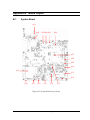
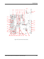
2.4
System Board Troubleshooting
This section describes how to determine if the system board is malfunctioning or not. Start
with Procedure 1 and continue with the other procedures as instructed. The procedures
described in this section are:
Procedure 1: Message Check
Procedure 2: Debugging Port Check
Procedure 3: Diagnostic Test Program Execution Check
Procedure 4: Replacement Check
Satellite P300 and Satellite Pro P300 Maintenance Manual (960-Q08)
15
2 Troubleshooting Procedures
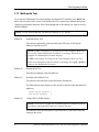
Procedure 1
Message Check
When the power is turned on, the system performs the Power On Self Test (POST) installed
in the BIOS ROM. The POST tests each IC on the system board and initializes it.
If an error message is shown on the display, perform Check 1.
If there is no error message, go to Procedure 2.
If MS-DOS or Windows XP is properly loaded, go to Procedure 4.
Check 1
If one of the following error messages is displayed on the screen, press the F1 key
as the message instructs. These errors occur when the system configuration
preserved in the RTC memory (CMOS type memory) is not the same as the actual
configuration or when the data is lost.
If you press the F1 key as the message instructs, the SETUP screen appears to set
the system configuration. If error message (b) appears often when the power is
turned on, replace the RTC battery. If any other error message is displayed,
perform Check 2.
Check 2
(a)
*** Bad HDD type ***
Check system. Then press [F1] key ......
(b)
*** Bad RTC battery ***
Check system. Then press [F1] key ......
(c)
*** Bad configuration ***
Check system. Then press [F1] key ......
(d)
*** Bad memory size ***
Check system. Then press [F1] key ......
(e)
*** Bad time function ***
Check system. Then press [F1] key ......
(f)
*** Bad check sum (CMOS) ***
Check system. Then press [F1] key ......
(g)
*** Bad check sum (ROM) ***
Check system. Then press [F1] key ......
If the following error message is displayed on the screen, press any key as the
message instructs.
The following error message appears when data stored in RAM under the resume
function is lost because the battery has become discharged or the system board is
damaged. Go to Procedure 3.
WARNING: RESUME FAILURE.
PRESS ANY KEY TO CONTINUE.
Satellite P300 and Satellite Pro P300 Maintenance Manual (960-Q08)
16
2 Troubleshooting Procedures
If any other error message displays, perform Check 3.
Check 3
The IRT checks the system board. When the IRT detects an error, the system
stops or an error message appears.
If one of the following error messages (1) through (17), (24) or (25) is displayed,
go to Procedure 4.
If error message (18) is displayed, go to the Keyboard Troubleshooting
Procedures.
If error message (19), (20) or (21) is displayed, go to the 2.5” HDD
Troubleshooting Procedures.
If error message (22) or (23) is displayed, go to the USB FDD Troubleshooting
Procedures.
(1)
(2)
(3)
(4)
(5)
(6)
(7)
(8)
(9)
(10)
(11)
(12)
(13)
(14)
(15)
(16)
(17)
(18)
(19)
(20)
(21)
(22)
(23)
(24)
(25)
PIT ERROR
MEMORY REFRESH ERROR
TIMER CH.2 OUT ERROR
CMOS CHECKSUM ERROR
CMOS BAD BATTERY ERROR
FIRST 64KB MEMORY ERROR
FIRST 64KB MEMORY PARITY ERROR
VRAM ERROR
SYSTEM MEMORY ERROR
SYSTEM MEMORY PARITY ERROR
EXTENDED MEMORY ERROR
EXTENDED MEMORY PARITY ERROR
DMA PAGE REGISTER ERROR
DMAC #1 ERROR
DMAC #2 ERROR
PIC #1 ERROR
PIC #2 ERROR
KBC ERROR
HDC ERROR
HDD #0 ERROR
HDD #1 ERROR
NO FDD ERROR
FDC ERROR
TIMER INTERRUPT ERROR
RTC UPDATE ERROR
Satellite P300 and Satellite Pro P300 Maintenance Manual (960-Q08)
17
2 Troubleshooting Procedures
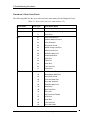
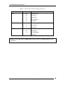
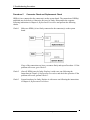
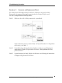
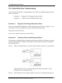
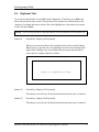
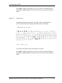
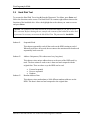
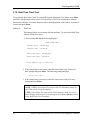
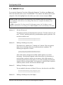
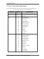
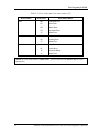
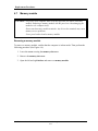
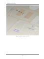
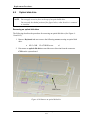
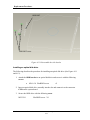
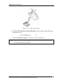
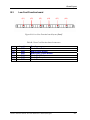
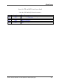
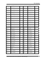
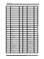
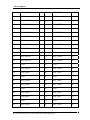
Procedure 2
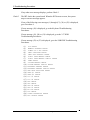
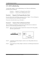
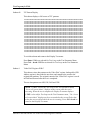
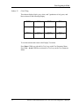
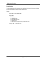
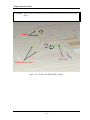
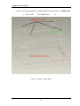
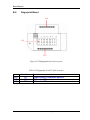
Debugging Port Check
Check the MiniPCI Debug board. The tool for debug port test is shown below.
Figure 2-2 A set of tool for debug port test
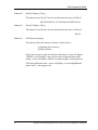
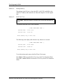
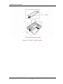
The test procedures are follows:
1. Replace Mini PCI debug port with Wireless LAN card, check LED in the Mini PCI
debug board
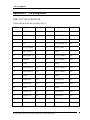
The following is a list of the Test Point codes written to port 80h at the start
of each routine, the beep codes issued for terminal errors, and a description
of the POST routine. Unless otherwise noted, these codes are valid for
Phoenix BIOS 4.0 Release 6.0.
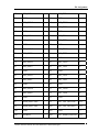
NOTE: The following routines are sorted by their test point numbers were assigned in the
BIOS code. Their actual order as executed during POST can
Be quite different.
Code Beeps POST Routine Description
02h
Verify Real Mode
03h
Disable Non-Maskable Interrupt (NMI)
04h
Get CPU type
06h
Initialize system hardware
08h
Initialize chipset with initial POST values
09h
Set IN POST flag
0Ah
Initialize CPU registers
0Bh
Enable CPU cache
0Ch
Initialize caches to initial POST values
0Eh
Initialize I/O component
0Fh
Initialize the local bus IDE
10h
Initialize Power Management
11h
Load alternate registers with initial POST values
12h
Restore CPU control word during warm boot
Satellite P300 and Satellite Pro P300 Maintenance Manual (960-Q08)
18
2 Troubleshooting Procedures
13h
Initialize PCI Bus Mastering devices
Code Beeps POST Routine Description
14h
Initialize keyboard controller
16h 1-2-2-3
BIOS ROM checksum
17h
Initialize cache before memory autosize
18h
8254 timer initialization
1Ah
8237 DMA controller initialization
1Ch
Reset Programmable Interrupt Controller
20h 1-3-1-1
Test DRAM refresh
22h 1-3-1-3
Test 8742 Keyboard Controller
24h
Set ES segment register to 4 GB
26h
Enable A20 line
28h
Autosize DRAM
29h
Initialize POST Memory Manager
2Ah
Clear 512 KB base RAM
2Ch 1-3-4-1
RAM failure on address line xxxx*
2Eh 1-3-4-3
RAM failure on data bits xxxx* of low byte of memory bus
2Fh
Enable cache before system BIOS shadow
30h 1-4-1-1
RAM failure on data bits xxxx* of high byte of memory bus
32h
Test CPU bus-clock frequency
33h
Initialize Phoenix Dispatch Manager
36h
Warm start shut down
38h
Shadow system BIOS ROM
3Ah
Autosize cache
3Ch
Advanced configuration of chipset registers
3Dh
Load alternate registers with CMOS values
42h
Initialize interrupt vectors
45h
POST device initialization
46h 2-1-2-3 Check ROM copyright notice
48h
Check video configuration against CMOS
49h
Initialize PCI bus and devices
4Ah
Initialize all video adapters in system
4Bh
QuietBoot start (optional)
4Ch
Shadow video BIOS ROM
4Eh
Display BIOS copyright notice
50h
Display CPU type and speed
51h
Initialize EISA board
52h
Test keyboard
54h
Set key click if enabled
58h 2-2-3-1 Test for unexpected interrupts
59h
Initialize POST display service
5Ah
Display prompt "Press F2 to enter SETUP"
5Bh
Disable CPU cache
5Ch
Test RAM between 512 and 640 KB
60h
Test extended memory
Satellite P300 and Satellite Pro P300 Maintenance Manual (960-Q08)
19
2 Troubleshooting Procedures
62h
64h
66h
67h
68h
69h
6Ah
6Bh
6Ch
6Eh
70h
72h
76h
7Ch
7Eh
80h
81h
82h
83h
84h
85h
86h
87h
88h
89h
8Ah
8Bh
8Ch
8Fh
90h
91h
92h
93h
95h
96h
97h
98h 1-2
Test extended memory address lines
Jump to UserPatch1
Configure advanced cache registers
Initialize Multi Processor APIC
Enable external and CPU caches
Setup System Management Mode (SMM) area
Display external L2 cache size
Load custom defaults (optional)
Display shadow-area message
Display possible high address for UMB recovery
Display error messages
Check for configuration errors
Check for keyboard errors
Set up hardware interrupt vectors
Initialize coprocessor if present
Disable onboard Super I/O ports and IRQs
Late POST device initialization
Detect and install external RS232 ports
Configure non-MCD IDE controllers
Detect and install external parallel ports
Initialize PC-compatible PnP ISA devices
Re-initialize onboard I/O ports.
Configure Motheboard Configurable Devices (optional)
Initialize BIOS Data Area
Enable Non-Maskable Interrupts (NMIs)
Initialize Extended BIOS Data Area
Test and initialize PS/2 mouse
Initialize floppy controller (optional)
Determine number of ATA drives (optional)
Initialize hard-disk controllers
Initialize local-bus hard-disk controllers
Jump to UserPatch2
Build MPTABLE for multi-processor boards
Install CD ROM for boot
Clear huge ES segment register
Fixup Multi Processor table
Search for option ROMs. One long, two short beeps on checksum failure
99h
9Ah
9Ch
9Dh
9Eh
9Fh
A0h
Check for SMART Drive (optional)
Shadow option ROMs
Set up Power Management
Initialize security engine (optional)
Enable hardware interrupts
Determine number of ATA and SCSI drives
Set time of day
Satellite P300 and Satellite Pro P300 Maintenance Manual (960-Q08)
20
2 Troubleshooting Procedures
A2h
Check key lock
A4h
Initialize Typematic rate
A8h
Erase F2 prompt
Code Beeps POST Routine Description
AAh
Scan for F2 key stroke
ACh
Enter SETUP
AEh
Clear Boot flag
B0h
Check for errors
B2h
POST done - prepare to boot operating system
B4h 1
One short beep before boot
B5h
Terminate QuietBoot (optional)
B6h
Check password (optional)
B9h
Prepare Boot
Bah
Initialize DMI parameters
BBh
Initialize PnP Option ROMs
BCh
Clear parity checkers
BDh
Display MultiBoot menu
BEh
Clear screen (optional)
BFh
Check virus and backup reminders
C0h
Try to boot with INT 19
C1h
Initialize POST Error Manager (PEM)
C2h
Initialize error logging
C3h
Initialize error display function
C4h
Initialize system error handler
C5h
PnPnd dual CMOS (optional)
C6h
Initialize notebook docking (optional)
C7h
Initialize notebook docking late
C8h
Force check (optional)
C9h
Extended checksum (optional)
D2h
Unknown interrupt
Satellite P300 and Satellite Pro P300 Maintenance Manual (960-Q08)
21
2 Troubleshooting Procedures
Code Beeps For Boot Block in Flash ROM
E0h
Initialize the chipset
E1h
Initialize the bridge
E2h
Initialize the CPU
E3h
Initialize system timer
E4h
Initialize system I/O
E5h
Check force recovery boot
E6h
Checksum BIOS ROM
E7h
Go to BIOS
E8h
Set Huge Segment
E9h
Initialize Multi Processor
EAh
Initialize OEM special code
EBh
Initialize PIC and DMA
ECh
Initialize Memory type
EDh
Initialize Memory size
EEh
Shadow Boot Block
EFh
System memory test
F0h
Initialize interrupt vectors
F1h
Initialize Run Time Clock
F2h
Initialize video
F3h
Initialize System Management Mode
F4h
1 Output one beep before boot
F5h
Boot to Mini DOS
F6h
Clear Huge Segment
F7h
Boot to Full DOS
Satellite P300 and Satellite Pro P300 Maintenance Manual (960-Q08)
22
2 Troubleshooting Procedures
Procedure 3
Diagnostic Test Program Execution Check
Execute the following tests from the Diagnostic Test Menu. These tests check the system
board. Refer to Chapter 3, Tests and Diagnostic, for more information on how to perform
these tests.
1. System test
2. Memory test
3. Keyboard test
4. Display test
5. Floppy Disk test
6. VGA test
7. VGA Memory test
8. Hard Disk test
9. CPU Temperature test
10. Main Battery test
11. BIOS test
12. CD-ROM/DVD-ROM test
13. System Status LED test
14. Wireless LAN test
15. LAN/Modem/Sound test
16. UUID test-DMI Information (Write DMI)
If an error is detected during these tests, go to Procedure 4.
Procedure 4
Replacement Check
System board may be faulty. Disassemble the computer following the steps described in
Chapter 4, Replacement Procedures and replace system board with a new one.
Satellite P300 and Satellite Pro P300 Maintenance Manual (960-Q08)
23
2 Troubleshooting Procedures
2.5 USB FDD Troubleshooting
To check if the USB FDD is malfunctioning or not, follow the troubleshooting procedures
below as instructed.
Procedure 1: FDD Head Cleaning Check
Procedure 2: Diagnostic Test Program Execution Check
Procedure 3: Connector Check and Replacement Check
Procedure 1
FDD Head Cleaning Check
FDD head cleaning is one option available in the Diagnostic Program.
After connecting USB FDD, insert the Diagnostics Disk in the floppy disk drive. Turn on the
computer and run the test. And then clean the FDD heads using the cleaning kit. If the FDD
still does not function properly after cleaning, go to Procedure 2.
Detailed operation is given in Chapter 3, Tests and Diagnostics.
If the test program cannot be executed on the computer, go to Procedure 3.
Satellite P300 and Satellite Pro P300 Maintenance Manual (960-Q08)
24
2 Troubleshooting Procedures
Procedure 2
Diagnostic Test Program Execution Check
Insert the Diagnostics Disk in the USB FDD, turn on the computer and run the test. Refer to
Chapter 3, Tests and Diagnostics, for more information about the diagnostics test procedures.
Make sure the floppy disk is formatted correctly and that the write protect tab is disabled.
Floppy disk drive test error codes and their status names are listed in Table 2-7. If any other
errors occur while executing the FDD diagnostics test, go to Check 1.
Table 2-7 FDD error code and status
Code
Check 1
Status
01h
Bad command
02h
Address mark not found
03h
Write protected
04h
Record not found
06h
Media replaced
08h
DMA overrun error
09h
DMA boundary error
10h
CRC error
20h
FDC error
40h
Seek error
60h
FDD not drive
80h
Time out error (Not ready)
EEh
Write buffer error
FFh
Data compare error
If the following message is displayed, disable the write protect tab on the floppy
disk by sliding the write protect tab to “write enable”. If any other message
appears, perform Check 2.
Write protected
Check 2
Make sure the floppy disk is formatted correctly. If it is, go to Procedure 3.
Satellite P300 and Satellite Pro P300 Maintenance Manual (960-Q08)
25
2 Troubleshooting Procedures
Procedure 3
Connector Check and Replacement Check
USB FDD is connected to USB port on system board and US board. US board is also
connected to system board by cable. The connection of cable and board may be defective.
Otherwise, they may be faulty. Disassemble the computer following the steps described in
Chapter 4, Replacement Procedures and perform the following checks.
USB FDD can be connected to the following 4 ports on system board.
Check 1
Make sure USB FDD is firmly connected to USB port. If the connection is loose,
connect firmly and repeat Procedure 2. If the problem still occurs, go to Check 2.
NOTE: When checking the connection, be sure to check it with care for the followings.
1. Cable can not be disconnected from the connector.
2. Cable is connected straight to the connector.
3. Cable is connected all the way seated in the connector.
4. Cable can not be broken.
Satellite P300 and Satellite Pro P300 Maintenance Manual (960-Q08)
26
2 Troubleshooting Procedures
Check 2
USB FDD may be faulty. Replace it with a new one. If the problem still occurs,
perform Check 3.
Check 3
Connect USB FDD to each port embedded on system board.
If it does not work properly when connected to CN6, CN7, CN31, CN35 or all
ports, perform Check 4.
Check 4
System board may be faulty. Replace it with a new one following the steps in
Chapter 4, Replacement Procedures.
Satellite P300 and Satellite Pro P300 Maintenance Manual (960-Q08)
27
2 Troubleshooting Procedures
2.6 2.5” HDD Troubleshooting
To check if 2.5” HDD is malfunctioning or not, follow the troubleshooting procedures below
as instructed.
Procedure 1: Partition Check
Procedure 2: Message Check
Procedure 3: Format Check
Procedure 4: Diagnostic Test Program Execution Check
Procedure 5: Connector Check and Replacement Check
CAUTION: The contents of the hard disk will be erased when the 2.5” HDD
troubleshooting procedures are executed. Transfer the contents of the hard
disk to floppy disks or other storage drive(s). For the backup, refer to the
User’s Manual.
Procedure 1
Partition Check
Insert the Toshiba MS-DOS system disk and start the computer. Perform the following
checks:
Check 1
Input C: and press Enter. If you cannot change to drive C, go to Check 2. If you
can change to drive C, go to Procedure 2.
Check 2
Input FDISK and press Enter. Choose Display Partition Information from the
FDISK menu. If drive C is listed in the Display Partition Information, go to Check
3. If drive C is not listed, return to the FDISK menu and choose the option to
create a DOS partition or a logical DOS drive on drive C. If the problem still
occurs, go to Procedure 2.
Check 3
If drive C is listed as active in the FDISK menu, go to Check 4. If drive C is not
listed as active, return to the FDISK menu and choose the option to set the active
partition for drive C. Then go to Procedure 2.
Check 4
Remove the system disk from the FDD and reboot the computer. If the problem
still occurs, go to Procedure 2. Otherwise, the 2.5” HDD is operating normally.
Satellite P300 and Satellite Pro P300 Maintenance Manual (960-Q08)
28
2 Troubleshooting Procedures
Procedure 2
Message Check
When the power is turned on, the system performs the Initial Reliability Test (IRT) installed
in the BIOS ROM. When the test detects an error, an error message is displayed on the screen.
Make sure no floppy disk is in the FDD. Turn on the computer and check the message on the
screen. When an OS starts from the 2.5” HDD, go to Procedure 3. Otherwise, start with
Check 1 below and perform the other checks as instructed.
Check 1
If any of the following messages appear, go to Procedure 3. If the following
messages do not appear, perform Check 2.
HDC ERROR
or
HDD #X ERROR
Check 2
(After 5 seconds this message will disappear.)
If either of the following messages appears, go to Check 3. If the following
messages do not appear, perform Check 4.
Insert system disk in drive
Press any key when ready .....
or
Non-System disk or disk error
Replace and press any key when ready
Check 3
Using the SYS command of the MS-DOS, transfer the system to the 2.5” HDD. If
the system is not transferred, go to Procedure 3. Refer to the MS-DOS Manual for
detailed operation.
If the following message appears on the display, the system program has been
transferred to the HDD.
System Transferred
If an error message appears on the display, perform Check 4.
Check 4
2.5” HDD(s) and the connector(s) of system board may be defective (Refer to the
steps described in Chapter 4, Replacement Procedures for disassembling.). Insert
HDD(s) to the connector(s) firmly. If it is (or they are) firmly connected, go to
Procedure 3.
Satellite P300 and Satellite Pro P300 Maintenance Manual (960-Q08)
29
2 Troubleshooting Procedures
Procedure 3
Format Check
The computer’s HDD is formatted using the MS-DOS FORMAT program or the physical
format program of the test program. To format the HDD, start with Check 1 below and
perform the other steps as required.
Refer to the MS-DOS Manual for the operation of MS-DOS. For the format by the test
program, refer to the Chapter 3.
Check 1
Format an 2.5” HDD using MS-DOS FORMAT command. Type as FORMAT
C:/S/U.
If 2.5” HDD can not be formatted, perform Check 2.
Check 2
Using the MS-DOS FDISK command, set the 2.5” HDD partition. If the partition
is not set, go to Check 3. If it is set, format 2.5” HDD using MS-DOS FORMAT
command.
Check 3
Using the Diagnostic Disk, format 2.5” HDD with a format option (physical
format). If HDD is formatted, set the 2.5” HDD partition using MS-DOS FDISK
command.
If you cannot format 2.5” HDD using the Tests and Diagnostic program, go to
Procedure 4.
Satellite P300 and Satellite Pro P300 Maintenance Manual (960-Q08)
30
2 Troubleshooting Procedures
Procedure 4
Diagnostic Test Program Execution Check
The HDD test program is stored in the Diagnostics Disk. Perform all of the HDD tests in the
Hard Disk Drive Test. Refer to Chapter 3, Tests and Diagnostics, for more information about
the HDD test program.
If an error is detected during the HDD test, an error code and status will be displayed. The
error codes and statuses are described in Table 2-8. If an error code is not displayed but the
problem still occurs, go to Procedure 5.
Table 2-8 2.5” Hard disk drive error code and status
Code
Status
05
HDD - HDC NOT RESET ERROR
07
HDD - DRIVE NOT INITIALIZE
09
HDD - DMA BOUNDARY ERROR
0B
HDD - BAD TRACK ERROR
BB
HDD - UNDEFINED ERROR
08
HDD - OVERRUN ERROR (DRQ ON)
01
HDD - BAD COMMAND ERROR
02
HDD - ADDRESS MARK NOT FOUND
04
HDD - RECORD NOT FOUND ERROR
10
HDD - ECC ERROR
20
HDD - HDC ERROR
40
HDD - SEEK ERROR
80
HDD - TIME OUT ERROR
11
HDD - ECC RECOVER ENABLE
AA
HDD - DRIVE NOT READY
CC
HDD - WRITE FAULT
E0
HDD - STATUS ERROR
0A
HDD - BAD SECTOR
EE
HDD - ACCESS TIME ERROR
DA
HDD - NO HDD
12
HDD - DMA CRC ERROR
Satellite P300 and Satellite Pro P300 Maintenance Manual (960-Q08)
31
2 Troubleshooting Procedures
Procedure 5
Connector Check and Replacement Check
HDD(s) is/are connected to the connector(s) on the system board. The connection of HDD(s)
and board may be defective. Otherwise, they may be faulty. Disassemble the computer
following instructions in Chapter 4, Replacement Procedures and perform the following
checks.
Check 1
Make sure HDD(s) is/are firmly connected to the connector(s) on the system
board.
If any of the connections are loose, reconnect firmly and repeat Procedure 1. If the
problem still occurs, go to Check 2.
Check 2
(One of) HDD(s) may be faulty. Replace it with a new one following the
instructions in Chapter 4, Replacement Procedures and check the operation. If the
problem still occurs, perform Check 3.
Check 3
System board may be faulty. Replace it with a new one following the instructions
in Chapter 4, Replacement Procedures.
Satellite P300 and Satellite Pro P300 Maintenance Manual (960-Q08)
32
2 Troubleshooting Procedures
2.7 Keyboard Troubleshooting
To check if the computer’s keyboard is malfunctioning or not, follow the troubleshooting
procedures below as instructed.
Procedure 1: Diagnostic Test Program Execution Check
Procedure 2: Connector and Replacement Check
Procedure 1
Diagnostic Test Program Execution Check
Execute the Keyboard Test (DIAGNOSTIC TEST) and Pressed key display test (ONLY
ONE TEST) in the Diagnostic Program. Refer to Chapter 3, Tests and Diagnostics, for more
information on how to perform the test program.
If an error occurs, go to Procedure 2. If an error does not occur, keyboard is functioning
properly.
Satellite P300 and Satellite Pro P300 Maintenance Manual (960-Q08)
33
2 Troubleshooting Procedures
Procedure 2
Connector and Replacement Check
The connection of cable and board may be defective. Otherwise, they may be faulty.
Disassemble the computer following the steps described in Chapter 4, Replacement
Procedures, and perform the following checks:
Check 1
Make sure keyboard cable is firmly connected to system board.
If the connection is loose, reconnect firmly and repeat Procedure 1. If the problem
still occurs, go to Check 2.
Check 2
Keyboard may be faulty. Replace it with a new one following the instructions in
Chapter 4, Replacement Procedures. If the problem still occurs, perform Check 3.
Check 3
System board may be faulty. Replace it with a new one following the instructions
in Chapter 4, Replacement Procedures.
Satellite P300 and Satellite Pro P300 Maintenance Manual (960-Q08)
34
2 Troubleshooting Procedures
2.8 Touch pad Troubleshooting
To check if the computer’s touch pad is malfunctioning or not, follow the troubleshooting
procedures below as instructed.
Procedure 1: Diagnostic Test Program Execution Check
Procedure 2: Connector and Replacement Check
Procedure 1
Diagnostic Test Program Execution Check
Execute the Touch pad test (ONLY ONE TEST) in the Diagnostic Program. Refer to Chapter
3, Tests and Diagnostics, for more information on how to perform the test program.
If an error occurs, go to Procedure 2. If an error does not occur, touch pad is functioning
properly.
Satellite P300 and Satellite Pro P300 Maintenance Manual (960-Q08)
35
2 Troubleshooting Procedures
Procedure 2
Connector and Replacement Check
The connection of cable and board may be defective. Otherwise, they may be faulty.
Disassemble the computer following the steps described in Chapter 4, Replacement
Procedures, and perform the following checks:
Check 1
Make sure the cable is firmly connected to system board.
If the connection is loose, reconnect firmly and repeat Procedure 1. If the problem
still occurs, go to Check 2.
Check 2
Touch Pad or the cable may be faulty. Replace it with a new one following the
instructions in Chapter 4, Replacement Procedures. If the problem still occurs,
perform Check 3.
Check 3
System board may be faulty. Replace it with a new one following the instructions
in Chapter 4, Replacement Procedures
Satellite P300 and Satellite Pro P300 Maintenance Manual (960-Q08)
36
Troubleshooting Procedures
2.9 Display Troubleshooting
To check if the computer’s display is malfunctioning or not, follow the troubleshooting
procedures below as instructed.
Procedure 1: External Monitor Check
Procedure 2: Diagnostic Test Program Execution Check
Procedure 3: Connector and Cable Check
Procedure 4: Replacement Check
Procedure 1
External Monitor Check
Connect an external monitor to the computer’s external monitor port, then boot the computer.
The computer automatically detects the external monitor.
If the external monitor works correctly, the internal LCD may be faulty. Go to Procedure 3.
If the external monitor appears to have the same problem as the internal monitor, system
board may be faulty. Go to Procedure 2.
Procedure 2
Diagnostic Test Program Execution Check
The Display Test program is stored in Diagnostics disk. This program checks the display
controller on system board. Insert the Diagnostics disk in the USB FDD, turn on the computer
and run the test. Refer to Chapter 3, Tests and Diagnostics for details. If an error is detected,
go to Procedure 3.
Satellite P300 and Satellite Pro P300 Maintenance Manual
37
Troubleshooting Procedures
Procedure 3
Connector and Cable Check
LCD Module is connected to system board by an LCD/FL cable. FL inverter board is also
connected to system board by an LCD/FL cable. And, fluorescent lamp is connected to FL
inverter board by HV cable. Their cables may be disconnected from system board or FL
inverter board. Disassemble the computer following the steps described in Chapter 4,
Replacement Procedures.
If the connection is loose, reconnect firmly and restart the computer. If the problem still
occurs, go to Procedure 4.
Satellite P300 and Satellite Pro P300 Maintenance Manual
38
Troubleshooting Procedures
Procedure 4
Replacement Check
Fluorescent lamp, FL inverter, LCD module, HV cable and LCD/FL cable are connected to
display circuits. Any of these components may be faulty. Refer to Chapter 4, Replacement
Procedures, for instructions on how to disassemble the computer and then perform the
following checks:
If fluorescent lamp does not light, perform Check 1.
If characters or graphics on the internal display are not displayed clearly, perform
Check 4.
If some screen functions do not operate properly, perform Check 4.
If fluorescent lamp remains lit when the display is closed, perform Check 5.
Check 1
Replace fluorescent lamp with a new one following the instructions in Chapter 4,
Replacement Procedures and test the display again. If the problem still occurs,
perform Check 2.
Check 2
LCD/FL cable may be faulty. Replace FL/LCD cable with a new one following the
instructions in Chapter 4, Replacement Procedure and test the display again. If the
problem still occurs, perform Check 3.
Check 3
FL inverter may be faulty. Replace FL inverter with a new one following the
instructions in Chapter 4, Replacement Procedure and test the display again. If the
problem still occurs, perform Check 4.
Check 4
LCD module may be faulty. Replace LCD module with a new one following the
instructions in Chapter 4, Replacement Procedure and test the display again. If the
problem still occurs, perform Check 5.
Check 5
System board may be faulty. Replace it with a new one following the instructions
in Chapter 4, Replacement Procedure.
Satellite P300 and Satellite Pro P300 Maintenance Manual
39
Troubleshooting Procedures
2.10 Optical Disk Drive Troubleshooting
To check if optical disk drive is malfunctioning or not, follow the troubleshooting procedures
below as instructed.
Procedure 1:
Diagnostic Test Program Execution Check
Procedure 2:
Connector Check and Replacement Check
Procedure 1
Diagnostic Test Program Execution Check
Execute the CD-ROM/DVD-ROM Test in the Diagnostic Program. Refer to Chapter 3, Tests
and Diagnostics for more information on how to perform the test program.
Prepare the tools before the test.
If any error is detected by the test, go to Procedure 2.
Procedure 2
Connector Check and Replacement Check
The connection of optical disk drive and system board may be defective. Otherwise, they may
be faulty. Disassemble the computer following the steps described in Chapter 4 and perform
the following checks:
Check 1
Make sure optical disk drive is firmly connected to the connector on system board.
If the connection is loose, reconnect it firmly and return to Procedure 2. If the
problem still occurs, perform Check 2.
Check 2
Optical disk drive may be faulty. Replace it with a new one following the steps in
Satellite P300 and Satellite Pro P300 Maintenance Manual
40
Troubleshooting Procedures
Chapter 4. If the problem still occurs, perform Check 3.
Check 3
System board may be faulty. Replace it with new one following the instructions in
Chapter 4.
Satellite P300 and Satellite Pro P300 Maintenance Manual
41
Troubleshooting Procedures
2.11 Modem Troubleshooting
To check if modem is malfunctioning or not, follow the troubleshooting procedures below as
instructed.
Procedure 1:
Diagnostic Test Program Execution Check
Procedure 2:
Connector Check and Replacement Check
Procedure 1
Diagnostic Test Program Execution Check
Execute Modem test in the LAN/Modem/Bluetooth/IEEE1394 test program. Refer to Chapter
3, Tests and Diagnostics for more information on how to perform the test program.
If any error is detected, perform Procedure 2.
Procedure 2
Connector Check and Replacement Check
MDC (Modem Daughter Card) is used as the modem for this computer. MDC is connected to
system board by connector CN43(REV.G) or CN43(GRIFFIN). And also, MDC is connected
to system and LAN board by modem cable. If modem malfunctions, the connection of cable,
board and module may be defective. Otherwise, they may be faulty.
Disassemble the computer following the steps described in Chapter 4 and perform the
following checks:
Satellite P300 and Satellite Pro P300 Maintenance Manual
42
Troubleshooting Procedures
Check 1
Make sure the following connections are firmly connected.
If any connector is disconnected, connect it firmly and return to Procedure 1. If the
problem still occurs, perform Check 2.
Satellite P300 and Satellite Pro P300 Maintenance Manual
43
Troubleshooting Procedures
Check 2
Modem cable may be faulty. Replace it with a new one. If the problem still occurs,
perform Check 3.
Check 3
MDC may be faulty. Replace it with a new one following the steps in Chapter 4. If
the problem still occurs, perform Check 4.
Check 4
Cable between MDC and system board may be faulty. Replace it with a new one
following the instructions in Chapter 4. If the problem still occurs, perform Check
5.
Check 6
System board may be faulty. Replace it with a new one following the instruction in
Chapter 4.
Satellite P300 and Satellite Pro P300 Maintenance Manual
44
Troubleshooting Procedures
2.12 LAN Troubleshooting
To check if the computer’s LAN is malfunctioning or not, follow the troubleshooting
procedures below as instructed.
Procedure 1:
Diagnostic Test Program Execution Check
Procedure 2:
Connector Check and Replacement Check
Procedure 1
Diagnostic Test Program Execution Check
Execute LAN test in the LAN/Modem test program. Refer to Chapter 3, Tests and Diagnostics
for more information on how to perform the test program.
If any error is detected by the test, go to Procedure 2.
Procedure 2
Connector Check and Replacement Check
The LAN function is embedded on system board. If LAN malfunctions, its connection is
defective or LAN cable and system board may be faulty.
Check 1
Make sure LAN cable is firmly connected to the connector CN9. If the problem
still occurs, perform Check 2.
Check 2
LAN cable may be faulty. Replace it with a new one. If the problem still occurs,
perform Check 3.
Check 3
System board may be faulty. Replace it with a new one following the instruction in
Chapter 4.
Satellite P300 and Satellite Pro P300 Maintenance Manual
45
Troubleshooting Procedures
2.13 Wireless LAN Troubleshooting
To check if the computer's Wireless LAN is malfunctioning or not, follow the troubleshooting
procedures below as instructed.
Procedure 1: Transmitting-Receiving Check
Procedure 2: Antennas' Connection Check
Procedure 3: Replacement Check
Procedure 1
Transmitting-Receiving Check
Before starting the test, make sure the wireless communication switch is set in the ON
position.
Check 1
Execute Wireless LAN test program to check the transmitting-receiving function
of wireless LAN. You will need a second computer that can communicate by
wireless LAN. Perform the test following the instructions described in Chapter 3.
If the computer passes the test, the function is correctly working. If the computer
does not pass the test, perform Procedure 2.
Satellite P300 and Satellite Pro P300 Maintenance Manual
46
Troubleshooting Procedures
Procedure 2
Antennas' Connection Check
The wireless LAN function-wiring diagram is shown below:
Any of the connections may be defective. Disassemble the computer following the steps
described in Chapter 4, Replacement Procedures, and perform the following checks:
Check 1
Make sure the wireless communication switch is “On”.
If the switch is “Off”, turn it “On”. If the problem still occurs, perform Check 2.
Check 2
Make sure wireless LAN card (Mini-PCI) is firmly connected to the CN21 on
system board. If the connector is defective, connect it firmly and perform
Procedure 1. If the problem still occurs, perform Check 3.
Check 3
Make sure that wireless LAN antenna cables (black and white) are firmly
connected to the connectors on Wireless LAN card. If wireless LAN antenna
cables are not connected properly, connect them firmly and perform Procedure 1.
If the problem still occurs, go to the procedure 3.
Satellite P300 and Satellite Pro P300 Maintenance Manual
47
Troubleshooting Procedures
Procedure 3
Replacement Check
Wireless LAN card, wireless LAN antenna or system board may be faulty. Refer to Chapter 4,
Replacement Procedures, for instructions on how to disassemble the computer and then
perform the following checks:
Check 1
Wireless LAN antenna may be faulty. Replace it with a new one following the
instructions in Chapter 4, Replacement Procedures. If the problem still occurs,
perform Check 2.
Check 2
Wireless LAN card may be faulty. Replace it with a new one following the
instructions in Chapter 4, Replacement Procedures. If the problem still occurs,
perform Check 3.
Check3
System board may be faulty. Replace it with a new one following the instructions
in Chapter 4, Replacement Procedures.
Satellite P300 and Satellite Pro P300 Maintenance Manual
48
Troubleshooting Procedures
2.14 Sound Troubleshooting
To check if the sound function is malfunctioning or not, follow the troubleshooting procedures
below as instructed.
Procedure 1: Connector Check
Procedure 2:
Procedure 1
Replacement Check
Connector Check
The connection of sound system is shown in the following figure.
As the connection may be defective, disassemble the PC and check each connection.
If the problem still occurs, go to Procedure 2.
Satellite P300 and Satellite Pro P300 Maintenance Manual
49
Troubleshooting Procedures
Procedure 2
Replacement Check
If External microphone/Headphone does not work properly, perform check 1.
If Internal microphone /Speaker does not work properly, perform check 2.
If HP out does not work properly, perform check 3.
If Volume control does not work properly, perform check 4.
Check 1
External microphone/Headphone may be faulty. Replace it with a new one
following the steps in Chapter 4.
Check 2
Internal microphone /Speaker may be faulty. Replace it with a new one following
the steps in Chapter 4. If the problem still occurs, perform Check 5.
Check 3
HP out may be faulty. Replace it with a new one following the steps in Chapter 4.
Check 4
Volume control may be faulty. Replace it with a new one following the steps in
Chapter 4.
Check 5
Flat cable between CN5 and CN39 may be faulty. Replace it with new cable
following the instructions in Chapter 4.
Satellite P300 and Satellite Pro P300 Maintenance Manual
50
Troubleshooting Procedures
2.15 Fingerprint Troubleshooting
To check if the computer’s Fingerprint is malfunctioning or not, follow the troubleshooting
procedures below as instructed.
Procedure 1: Connector Check and Replacement Check
Procedure 1
Diagnostic Test Program Execution Check
Execute Fingerprint test in the test program. Refer to Chapter 3, Tests and Diagnostics for
more information on how to perform the test program.
If any error is detected, perform Procedure 2.
Procedure 2
Connector Check and Replacement Check
The Fingerprint function is embedded on system board. If Fingerprint malfunctions, its
connection is defective or Fingerprint cable and system board may be faulty.
Check 1
Make sure Fingerprint cable is firmly connected to the connector CN11(REV.G) or
CN11(Griffin). If the problem still occurs, perform Check 2.
Check 2
Fingerprint cable may be faulty. Replace it with a new one. If the problem still
occurs, perform Check4.
Check 3
Fingerprint may be faulty. Replace it with a new one following the steps in
Chapter 4. If the problem still occurs, perform Check 4.
Check 4
System board may be faulty. Replace it with a new one following the instruction in
Satellite P300 and Satellite Pro P300 Maintenance Manual
51
Troubleshooting Procedures
Chapter 4.
Satellite P300 and Satellite Pro P300 Maintenance Manual
52
Troubleshooting Procedures
2.16 Bluetooth Troubleshooting
To check if the computer’s Bluetooth is malfunctioning or not, follow the troubleshooting
procedure below as instructed.
Procedure 1: Connector Check and Replacement Check
Procedure 1
Connector Check and Replacement Check
The Bluetooth function is connected to system board. If Bluetooth malfunctions, its
connection is defective or Bluetooth cable and system board may be faulty.
Check 1
Make sure Bluetooth cable is firmly connected to the connector CN14(REV.G) or
CN14(Griffin). If the problem still occurs, perform Check 2.
Check 2
Bluetooth cable may be faulty. Replace it with a new one. If the problem s till
occurs, perform Check 3.
Check 3
Bluetooth may be faulty. Replace it with a new one following the steps in Chapter
4. If the problem still occurs, perform Check 4.
Check 4
System board may be faulty. Replace it with a new one following the instruction in
Chapter 4.
Satellite P300 and Satellite Pro P300 Maintenance Manual
53
Troubleshooting Procedures
Satellite P300 and Satellite Pro P300 Maintenance Manual
54
Test Program for Field.
Chapter 3
Diagnostic Programs
Satellite P300 and Satellite Pro P300 Tests and Diagnostics Manual
1
Test Program for Field.
Chapter 3 Contents
3.1
Tests and Diagnostics Software Overview ............................................................... 3
3.2
Executing the Diagnostic Test .................................................................................. 4
3.3
Subtest names............................................................................................................ 8
3.4
System Test............................................................................................................. 11
3.5
Memory Test........................................................................................................... 13
3.6
Keyboard Test......................................................................................................... 17
3.7
Display Test ............................................................................................................ 20
3.8
Floppy Disk Test..................................................................................................... 35
3.9
Hard Disk Test ........................................................................................................ 37
3.10 Real Time Clock Test ............................................................................................. 40
3.11 Cache Memory Test................................................................................................ 42
3.12 High Resolution Display Test................................................................................. 44
3.13 Multimedia Test ...................................................................................................... 50
3.14 MEMORY2 Test..................................................................................................... 51
3.15 Error Codes and Error Status Names ...................................................................... 53
3.16 Running Test........................................................................................................... 55
3.17 DMI INFOEMATION ............................................................................................ 56
3.17.1
Check DMI Information ................................................................................. 56
3.17.2
Write DMI Information................................................................................... 56
3.17.3
Computrace Disabled...................................................................................... 58
3.18 Log Utilities ............................................................................................................ 59
3.18.1
Operations ....................................................................................................... 59
3.19 System Configuration ............................................................................................. 61
3.20 Running Test Edit Item........................................................................................... 62
3.20.1
Function Description....................................................................................... 62
3.20.2
Operation Description..................................................................................... 62
3.21 Common Tests and Operation ................................................................................ 64
3.21.1
How to operate a window ............................................................................... 64
3.21.2
How to Stop the Test Program........................................................................ 64
3.21.3
Test Status Screen ........................................................................................... 64
3.21.4
Test Stop Display............................................................................................ 66
3.21.5
How to enter data ............................................................................................ 66
2
Satellite P300 and Satellite Pro P300 Tests and Diagnostics Manual
Test Program for Field.
3.1
Tests and Diagnostics Software Overview
This chapter explains how to use the Tests and Diagnostics Software for the Satellite P300
and Satellite Pro P300 computer systems.
NOTES: Before starting the Tests and Diagnostics software:
1. Check all cables for loose connections.
2. Exit any application and close Windows.
The Diagnostics Menu consists of the following options:
Diagnostic Test
Running Test
DMI Information
Log Utilities
System Configuration
Option
The Diagnostic Test Menu consists of the following functional tests:
System Test
Memory Test
Keyboard Test
Display Test
Floppy Disk Test
Hard Disk Test
Real Time Clock Test
Cache Memory Test
High Resolution Display Test
Multimedia Test
Memory2 Test
FDD & HDD Error Retry Count Set
The following equipment is required to perform some of the diagnostic test programs:
The Diagnostics Disk (all tests)
A formatted working disk for the floppy disk drive test (all tests)
A CD test media (Toshiba Backup CD ROM for the CD-ROM test)
The following sections detail the tests contained within the Diagnostic Test Menu. Refer to
Sections 3.18, 3.19, 3.20 and, 3.21 for detailed information on the remaining functions of the
Tests and Diagnostics software.
Satellite P300 and Satellite Pro P300 Tests and Diagnostics Manual
3
Test Program for Field.
3.2
Executing the Diagnostic Test
DOS is required to run the Diagnostics Program. To start the programs follow these steps:
1. Create a DOS bootable disk and copy all the files from the Tests and Diagnostics
software to the disk.
2. Insert the boot disk into the computer’s floppy disk drive and turn on the computer.
The following screen displays:
TOSHIBA Satellite(Pro) P300 Diagnostics
Version v1.10
ESC
::Select item
:Escape
[ DIAGNOSTICS MENU ]
01.DIAGNOSTIC TEST
02.RUNNING TEST
03.DMI INFORMATION
04.LOG UTILITIES
05.SYSTEM CONFIGURATION
06.OPTION
99.EXIT
3. To select the Diagnostic Test from the Diagnostics Menu use the arrow keys to set the
highlight bar to 01 and press Enter.
4
Satellite P300 and Satellite Pro P300 Tests and Diagnostics Manual
Test Program for Field.
The following menu displays:
TOSHIBA Satellite(Pro) P300 Diagnostics
Version V1.10
ESC
::Select item
:Escape
[ DIAGNOSTICS MENU ]
01.
02.
03.
04.
05.
01.
01.
06.
02.
99.
03.
04.
05.
06.
07.
DIAGNOSTIC TEST
RUNNING TEST
DMI INFORMATION [ DIAGNOSTIC TEST MENU ]
LOG UTILITIES
SYSTEM
CONFIGURATION
SYSTEM TEST
TEST
08. CACHE MEMORY TEST
SYSTEM
OPTION
MEMORY TEST
09. HIGH RESOLUTION DISPLAY TEST
EXIT
KEYBOARD TEST
10. MULTIMEDIA TEST
DISPLAY TEST
11. MEMORY2 TEST
FLOPPY DISK TEST
88. FDD&HDD ERROR RETRY COUNT SET
HARD DISK TEST
99. EXIT TO DIAGNOSTICS MENU
REAL TIME CLOCK TEST
:Select item Enter:Decision item Esc:Escape
Refer to Sections 3.4 through 3.14 for detailed descriptions of Diagnostics Tests 1 through
11. Item 88 sets the floppy disk drive and hard disk drive error retry count. Item 99 exits the
submenu of the Diagnostic Test and returns to the Diagnostics Menu.
Satellite P300 and Satellite Pro P300 Tests and Diagnostics Manual
5
Test Program for Field.
4. Select the subtest you want to execute and press Enter. The following menu displays:
TOSHIBA Satellite(Pro) P300 Diagnostics
Version V1.10
ESC
: :Select item
:Escape
[ DIAGNOSTICS MENU ]
[ SYSTEM TEST ]
01. DIAGNOSTIC TEST
02. RUNNING TEST
01. FAN ON/OFF
03. DMI INFORMATION
01.
FAN
ON/OFF
02.TEST
Battery
[ DIAGNOSTIC
MENU Test
]
04. LOG UTILITIES
03.
CPU
Temperature
05. SYSTEM CONFIGURATION
DIAGNOSTIC
TEST MENU
01.
SYSTEM
01.OPTION
SYSTEM TEST
TEST
9. 99.
REALExit
TIMEtoCLOCK
TEST
06.
02.
MEMORY
TEST
08.
CACHE
MEMORY
TEST
99. EXIT
03. KEYBOARD TEST
09. HIGH RESOLUTION DISPLAY TEST
04. DISPLAY TEST
10. MULTIMEDIA TEST
05. FLOPPY DISK TEST
11. MEMRY2 TEST
06. HARD DISK TEST
88. FDD&HDD ERROR RETRY COUNT SET
07. REAL TIME CLOCK TEST 99. EXIT TO DIAGNOSTICS MENU
5. Select the desired test from the subtest menu and press Enter. The following Test
Parameter menu displays:
TOSHIBA Satellite(Pro) P300 Diagnostics
Version V1.10
ESC
: :Select item
:Escape
[ DIAGNOSTICS MENU ]
[ SYSTEM TEST ]
[ TEST PARAMETER ]
01. DIAGNOSTIC TEST
01.
01. FAN
FAN ON/OFF
01.
Go
01.TEST
Go To
To Test
Test02. Battery Test
02. RUNNING
02. Test Loop 03.: CPU
YESTemperature
03. DISK UTILITIES
[ DIAGNOSTIC
TEST
MENU ]
03. Error
Stop99.: Exit
NO to
04. LOG UTILITIES
DIAGNOSTIC TEST MENU
05. SYSTEM CONFIGURATION
01.
TEST
09. REAL TIME CLOCK TEST
01. SYSTEM
SYSTEM
TEST
06.
OPTION
02.
MEMORY
TEST
10. NPX TEST
99.KEYBOARD
EXIT
03.
TEST
11. HIGH RESOLUTION DISPLAY TEST
04. DISPLAY TEST
12. MULTIMEDIA TEST
05. FLOPPY DISK TEST
13. USB TEST
06. HARD DISK TEST
14. MEMORY2 TEST
07. REAL TIME CLOCK TEST 88. FDD&HDD ERROR RETRY COUNT SET
99. EXIT TO DIAGNOSTICS MENU
Use the arrow keys to highlight the desired option and press Enter.
6
Satellite P300 and Satellite Pro P300 Tests and Diagnostics Manual
Test Program for Field.
NOTES: The Item2 and 3 of Test Parameter are not used by some tests.
Go To Test
Move the highlight bar to Go To Test and press Enter to start executing the test.
Test Loop
Select NO to return the screen to the subtest menu after the test is complete.
Select YES to set the test to run continuously until it is halted by the user.
Error Stop
Select NO to keep the test running even if an error is found.
Select YES to stop the test program when an error is found and display the HALT
OPERATION screen as shown below:
[[ HALT OPERATION ]]
1: Test end
2: Continue
3: Retry
These three selections have the following functions:
1: Terminates the test program and exits to the subtest menu.
2: Continues the test from the error.
3: Restarts the test from the beginning.
Use the arrow keys to move the cursor to the desired option and press Enter.
Table 3-1 in Section 3.3 lists the function of each test on the subtest menu. Table 3-2 in
Section 3.15 lists the error codes and error status for each error.
Satellite P300 and Satellite Pro P300 Tests and Diagnostics Manual
7
Test Program for Field.
3.3
Subtest names
Table 3-1 lists the subtest names for each test program in the Diagnostic
Test menu.
Table 3-1 Subtest Names(1/3)
No.
01
02
03
04
8
Test Name
SYSTEM TEST
MEMORY TEST
KEYBOARD TEST
DISPLAY TEST
No.
Subtest Name
01
FAN ON/OFF check
02
Battery TEST
03
CPU Temperature
01
Conventional Memory
02
Protected Mode
03
Protected Mode (32MB-MAX)
04
RAM Refresh
05
Stress Test
01
Pressed Key Display [109 KBD]
02
Pressed Key Display [105 KBD]
03
Pressed Key Display [104 KBD]
04
Hot Key Display [7 KBD]
05
Hot Key Display [1 KBD]
06
PS/2 Mouse (Pointing 2Button)
01
Character Attributes
02
Character Set
03
80* 25 Character Display
04
320* 200 Graphics Display
05
640* 200 Graphics Display
06
640* 480 Graphics Display
07
Display Page
08
“H” Pattern Display
09
Video DAC Register W/R/C
10
Color Graphics Display
11
Color Attributes Display
12
Color Tiling
Satellite P300 and Satellite Pro P300 Tests and Diagnostics Manual
Test Program for Field.
Table 3-1 Subtest Names(2/3)
No.
05
06
07
08
09
Test Name
No.
Subtest Name
01
Sequential Read
02
Sequential W/R/C
03
Random Address/Data
04
Write Specified Address
05
Read Specified Address
01
Sequential Read
02
Address Uniqueness
03
Random Address Data
04
Cross Talk and Peek Shift
05
Write Specified Address
06
Read Specified Address
07
Sequential Write
08
W-R-C Specified Address
01
Real Time Test
02
Backup Memory Test
03
Real Time Carry Test
01
Constant Data Test
02
Address Pattern Test
03
Increment/Decrement Test
04
Bit Shift Pattern Test
05
*Write Disturb Test
06
Checker Board Test
07
Marching Test
08
Working Data Test
HIGH RESOLUTION
01
VRAM W/R/C Test
DISPLAY TEST
02
640* 480 Mode Display
03
800* 600 Mode Display
04
1024* 768 Mode Display
05
“H” Pattern Display
06
Focus Test (“E” Pattern)
FLOPPY DISK TEST
HARD DISK TEST
REAL TIME CLOCK
TEST
CACHE MEMORY
TEST
Satellite P300 and Satellite Pro P300 Tests and Diagnostics Manual
9
Test Program for Field.
Table 3-1 Subtest Names(3/3)
No.
10
11
Test Name
MULTIMEDIA TEST
MEMORY2
No.
Subtest Name
01
Sequential Read Test
02
Random Read Test
03
Read Specified Address Test
04
1 point W/R/C Test
01
All one/zero Test
02
Walking 1/Walking 0 Test(Left)
03
Walking 1/Walking 0 Test(Right)
04
Walking 1/Walking 0 Test(Left /Right)
*This test cannot support.
10
Satellite P300 and Satellite Pro P300 Tests and Diagnostics Manual
Test Program for Field.
3.4
System Test
To execute the System Test select 01 from the Diagnostic Test Menu, press Enter and follow
the directions on the screen. The System Test contains three subtests. Move the highlight bar
to the subtest you want to execute and press Enter.
Subtest 01
FAN ON/OFF Checking
Select 1,2,3 to control FAN on/off , 1=Fan on , 2=Fan off , 3=Exit .
[BU1FAN.EXE] Program Version : 1.0
1: Fan On 2: Fan Off 3: Exit
Fan1 Status On Fan1RPM : 5000 or Fan1 Status OFF Fan1RPM : 0
Subtest 02
Battery Test
This will display battery information for check , press [ESC] to exit .
[BOIPCU.EXE] Program Version : 1.0 03-27-2007
voltage
: 12522 mV
Remaining capacity alarm
temperature
: 24.4 ‘C
Remaining time alarm
current
: 1330 mA
Battery mode
average current
: 1327 mA
AtRate
relative state of charge : 93 %
At rate time to full
absolute state of charge : 89 %
At rate time to empty
remaining capacity
: 3546 mAh
At rate O. K.
full charge capacity
: 3800 mAh
Maximun error
run time to empty
: -1 min.
Charging current
average time to empty
: -1 min.
Charging voltage
average time to full
: 101 min.
Manufacturer name
cycle count
: 10 times
Device name
design capacity
: 4000 mAh
Device chemistry
design voltage
: 11100 mV
Manufacturer data
specification information : 2.1
Manufacture date
serial no.
: 32009
STATUS
: INIT
: 400 mAh
: 10 min
:0
: 0 mA
: 65535 min
: 65535 min
: FFFF
:2%
: 2800 mA
: 12600 mA
: SANYO
: NS2P3SZDNVWR
: LION
:0
: 9/13/2005
Press [ESC] KEY to exit
Satellite P300 and Satellite Pro P300 Tests and Diagnostics Manual
11
Test Program for Field.
Subtest 03
CPU Temperature
This will display CPU Temperature for check , press [ESC] to exit .
[CPU_TEMP.EXE] Program Version : 1.0 03-27-2007
CPU Temperature : XX
12
Satellite P300 and Satellite Pro P300 Tests and Diagnostics Manual
Test Program for Field.
3.5
Memory Test
To execute the Memory Test select 02 from the Diagnostic Test Menu, press Enter and
follow the directions on the screen. The Memory Test contains five subtests that test the
computer’s memory. Move the highlight bar to the subtest you want to execute and press
Enter.
NOTE: If NO is selected for Test Loop on the Test Parameter menu, the Test Status
screen displays while the test is executing. When the test is complete the Memory Test
menu displays.
If YES is selected for Test Loop on the Test Parameter menu, the Test Status screen
displays while the test is executing. Press Ctrl + break to return to the Memory Test menu.
Subtest 01
Conventional Memory
This subtest first writes test data patterns to conventional memory (0 to 640
KB), then reads the new data and compares the result with the original data
patterns.
If a compare error occurs, the write data, read data, and test address display on
the screen. Addresses are displayed in 4KB increments during the test.
Test Process:
1. Byte Enable Test
One bit write/ 8 bit read” is executed and the new data is compared
with the original data.
Test data = CCAA5533H, 80000000H
2. Byte Enable Test
“One bit write/16 bit read” is executed and the new data is compared
with the original data.
Test data = CCAA5533H, 80000000H
3. Data bus test
“One bit write/16 bit read” is executed and the new data is compared
with the original data.
Test data = 1H, 2H, 4H, 8H, 10H, through 80000000H.
4. Fixed data test
“16 bit write/ 16 bit read” is executed and the new data is compared
to the original data.
Test data = FFFFFFFFH, 00000000H, 80018001H
Satellite P300 and Satellite Pro P300 Tests and Diagnostics Manual
13
Test Program for Field.
5. Address pattern test
“16 bit write and 16 bit read” of address pattern data is executed and
the new data is compared with the original data.
Test data = 0000H, 0004H, 0008H, 000CH,...8000H, 8004H, through
FFECH
Subtest 02
Protected Mode
This subtest first writes data patterns and address data from 1 to 32 MB, then
reads the new data and compares the result with the original data patterns.
Addresses are displayed in 64KB increments during the test.
.
Test Process:
1. Byte Enable Test
One bit write/ 8 bit read” is executed and the new data is compared
with the original data.
Test data = CCAA5533H, 80000000H
2. Byte Enable Test
“One bit write/16 bit read” is executed and the new data is compared
with the original data.
Test data = CCAA5533H, 80000000H
3. Data bus test
“One bit write/16 bit read” is executed and the new data is compared
with the original data.
Test data = 1H, 2H, 4H, 8H, 10H, through 80000000H.
4. Fixed data test
“16 bit write/ 16 bit read” is executed and the new data is compared
to the original data.
Test data = FFFFFFFFH, 00000000H, 80018001H
5. Address pattern test
“16 bit write and 16 bit read” of address pattern data is executed and
the new data is compared with the original data.
Test data = 0000H, 0004H, 0008H, 000CH,...8000H, 8004H, through
FFECH
Subtest 03
Protected Mode [32MB - MAX]
This subtest first writes data patterns and address data from 32MB to the
maximum installed memory, reads the new data, and then compares the result
14
Satellite P300 and Satellite Pro P300 Tests and Diagnostics Manual
Test Program for Field.
with the original data patterns. Addresses are displayed in 64KB increments
during the test.
Test Process:
1. Byte Enable Test
One bit write/ 8 bit read” is executed and the new data is compared
with the original data.
Test data = CCAA5533H, 80000000H
2. Byte Enable Test
“One bit write/16 bit read” is executed and the new data is compared
with the original data.
Test data = CCAA5533H, 80000000H
3. Data bus test
“One bit write/16 bit read” is executed and the new data is compared
with the original data.
Test data = 1H, 2H, 4H, 8H, 10H, through 80000000H.
4. Fixed data test
“16 bit write/ 16 bit read” is executed and the new data is compared
to the original data.
Test data = FFFFFFFFH, 00000000H, 80018001H
5. Address pattern test
“16 bit write and 16 bit read” of address pattern data is executed and
the new data is compared with the original data.
Test data = 0000H, 0004H, 0008H, 000CH,...8000H, 8004H, through
FFECH
Subtest 04
RAM Refresh
This subtest writes a data pattern (CCAA5533H ) in 4KB from 0 to the
maximum installed memory, then waits for a memory refresh cycle (16 ms or
more), reads the new data, and compares the result with the original data
pattern.
Satellite P300 and Satellite Pro P300 Tests and Diagnostics Manual
15
Test Program for Field.
Test Process:
1. Checks the memory size to determine the maximum size of installed
memory.
2. Tests memory addresses 0 to the maximum installed.
3. Writes, reads, and compares test data after a memory refresh cycle
(16ms or more).
NOTE: There may be a short delay between write and read operations,
depending on the memory size.
Subtest 05
Stress Test
This subtest writes the following 16KB data patterns to the Write/Read Buffer
in conventional memory.
data:
16
FFFFFFFFFFFFFFFF0000000000000000
5555555555555555AAAAAAAAAAAAAAAA
CCCCCCCCCCCCCCCC3333333333333333
0000000000000000FFFFFFFFFFFFFFFF
AAAAAAAAAAAAAAAA5555555555555555
3333333333333333CCCCCCCCCCCCCCCC
FFFFFFFFFFFFFFFF0000000000000000
0000000000000000FFFFFFFFFFFFFFFF
5555555555555555AAAAAAAAAAAAAAAA
AAAAAAAAAAAAAAAA5555555555555555
CCCCCCCCCCCCCCCC3333333333333333
3333333333333333CCCCCCCCCCCCCCCC
Satellite P300 and Satellite Pro P300 Tests and Diagnostics Manual
Test Program for Field.
3.6
Keyboard Test
To execute the Keyboard Test select 03 from the Diagnostic Test Menu, press Enter and
follow the directions on the screen. The Keyboard Test contains five subtests that test the
computer’s keyboard and mouse actions. Move the highlight bar to the subtest you want to
execute and press Enter.
NOTE: The Test Loop and Error Stop parameters are not enabled for the Keyboard test.
Subtest 01
Pressed Key Display [109 Keyboard]
When you execute this subtest, the keyboard layout is drawn on the display.
When any key is pressed, the corresponding key on the screen changes from
light to dark. Holding a key down enables the auto-repeat function which
causes the key’s display character to blink.
[[[ Press Key Display ]]]
Layout of a keyboard (109 keys)
Subtest 02
Pressed Key Display [105 Keyboard]
This subtest is used for the 105 keyboard and functions the same as Subtest 1.
Subtest 03
Pressed Key Display [104 Keyboard]
This subtest is used for the 104 keyboard and functions the same as Subtest 1.
Satellite P300 and Satellite Pro P300 Tests and Diagnostics Manual
17
Test Program for Field.
Subtest 04
Hot Key Display [7 Key]
This subtest is used for the 7 hot key and functions the same as Subtest 1.
MUTE MUSIC PLAY STOP BACK NEXT WLAN
Subtest 05
Hot Key Display [1 Key]
This subtest is used for the 1 hot key and functions the same as Subtest 1.
WLAN
Subtest 06
PS/2 Mouse (Pointing)
This subtest checks the function of mouse as shown below.
A) Pointing device (mouse)
B) Mouse buttons
Please move cursor to upper left and press left button , screen will display
<PRESS> in left rectangle , move cursor to lower right and press right
button , screen will display <PRESS> in right rectangle , the program exit .
If left and right button short , screen will display <Left and Right Button
maybe short > , the program exit .
18
Satellite P300 and Satellite Pro P300 Tests and Diagnostics Manual
Test Program for Field.
LEFT
PRESS
TOUCH_PAD TEST
RIGHT
PRESS
Please Do Not Press the Left and Right Button At The Same Time
Satellite P300 and Satellite Pro P300 Tests and Diagnostics Manual
19
Test Program for Field.
3.7
Display Test
To execute the Display Test select 04 from the Diagnostic Test Menu, press Enter and
follow the directions displayed on the screen. The Display Test contains twelve subtests that
test the display in various modes. Move the highlight bar to the subtest you want to execute
and press Enter.
Subtest 01
Character Attributes
This subtest displays character attributes and color attributes. The character
attributes are: normal, intensified, reverse, and blinking. The color attributes
are: blue, red, magenta, cyan, yellow, and white. These seven colors each
display a background color, foreground color and high resolution color. The
screen below displays when this subtest is executed.
CHARACTER ATTRIBUTES
NEXT LINE SHOWS NORMAL DISPLAY
NNNNNNNNNNNNNNNNNNNNNNNNNNNNNNNN
NEXT LINE SHOWS INTENSIFIED DISPLAY
IIIIIIIIIIIIIIIIIIIIIIIIIIIIIIII
NEXT LINE SHOWS REVERSE DISPLAY
RRRRRRRRRRRRRRRRRRRRRRRRRRRRRRRR
RRRRRRRRRRRRRRRRRRRRRRRRRRRRRRRR
NEXT LINE
SHOWS BLINKING DISPLAY
BBBBBBBBBBBBBBBBBBBBBBBBBBBBBBBB
BLUE
RED
MAGENTA
GREEN
CYAN
YELLOW
WHITE
Press
[ Enter ] KEY
To exit this subtest and return to the Display Test menu:
20
Satellite P300 and Satellite Pro P300 Tests and Diagnostics Manual
Test Program for Field.
Press Enter if NO was selected for Test Loop on the Test Parameter Menu.
Press Ctrl + break if YES was selected for Test Loop on the Test Parameter
Menu.
Subtest 02
Character Set
This subtest displays the character codes 00H - FFH, using Mode 01H
(40*25). The screen below displays when this subtest is executed.
CHARACTER SET IN 40*25
Press
[Enter] Key
To exit this subtest and return to the Display Test menu:
Press Enter if NO was selected for Test Loop on the Test Parameter Menu.
Press Ctrl + break if YES was selected for Test Loop on the Test Parameter
Menu.
Satellite P300 and Satellite Pro P300 Tests and Diagnostics Manual
21
Test Program for Field.
Subtest 03
80 * 25 Character Display
This subtest uses 80*25 video resolution to display character codes 20H 7EH using Mode 03H (80*25). The data displayed is shifted 1 byte to the left
for each line as shown below.
80*25 CHARACTER DISPLAY
01234567890123456789012345678901234567890123456789012345678901234567890123456789
!”#$%&’()*=,.-/0123456789:;Ù?@ABCDEFGHIJKLMNOPQRSTUVWXYZ[\]^_’abcdefghIjklmno
!”#$%&’()*=,.-/0123456789:;Ù?@ABCDEFGHIJKLMNOPQRSTUVWXYZ[\]^_’abcdefghIjkl mnop
”#$%&’()*=,.-/0123456789:;Ù?@ABCDEFGHIJKLMNOPQRSTUVWXYZ[\]^_’abcdefghIjklmnopq
#$%&’()*=,.-/0123456789:;Ù?@ABCDEFGHIJKLMNOPQRSTUVWXYZ[\]^_’abcdefghIjklmnopqr
$%&’()*=,.-/0123456789:;Ù?@ABCDEFGHIJKLMNOPQRSTUVWXYZ[\]^_’abcdefghIjklmnopqrs
%&’()*=,.-/0123456789:;Ù?@ABCDEFGHIJKLMNOPQRSTUVWXYZ[\]^_’abcdefghIjklmnopqrst
&’()*=,.-/0123456789:;Ù?@ABCDEFGHIJKLMNOPQRSTUVWXYZ[\]^_’abcdefghIjkl mnopqrstu
’()*=,.-/0123456789:;Ù?@ABCDEFGHIJKLMNOPQRSTUVWXYZ[\]^_’abcdefghIjklmnopqrstuv
Shifted to the left one letter by one letter.
23456789:;Ù?@ABCDEFGHIJKLMNOPQRSTUVWXYZ[\]^_’abcdef gh I j k l mnopqrst
3456789:;Ù?@ABCDEFGHIJKLMNOPQRSTUVWXYZ[\]^_’abcdef gh I j k l mnopqrst
456789:;Ù?@ABCDEFGHIJKLMNOPQRSTUVWXYZ[\]^_’abcdef gh I j k l mnopqrst
Press [Enter] KEY
To exit this subtest and return to the Display Test menu:
Press Enter if NO was selected for Test Loop on the Test Parameter Menu.
Press Ctrl + break if YES was selected for Test Loop on the Test Parameter
Menu.
22
Satellite P300 and Satellite Pro P300 Tests and Diagnostics Manual
Test Program for Field.
Subtest 04
320 * 200 Character Display
This subtest uses 320*200 video resolution to display green, red and yellow
followed by cyan, magenta, and white. The screen below shows the displays
when this subtest is executed.
320 * 200 GRAPHICS DISPLAY
COLOR SET 0 : [ 4 ]
GREEN
CYAN
RED
MAGENTA
YELLOW
WHITE
Press ENTER to display the following sixteen colors: black, blue, green,
cyan, red, magenta, brown, white, dark gray, light blue, light green, light cyan,
light red, light magenta, yellow, and intensified white.
Satellite P300 and Satellite Pro P300 Tests and Diagnostics Manual
23
Test Program for Field.
320*200 GRAPHICS DISPLAY
BLACK
:
[ D ]
D
GRAY
BLUE
L
BLUE
GREEN
L
GREEN
CYAN
L
CYAN
RED
L
RED
MAGENTA
L
MAGENTA
BROWN
YELLOW
WHITE
I
WHITE
Press [Enter] KEY
Press ENTER to display 64 gradations of red, green, blue and white on the
screen
320*200 GRAPHICS DISPLAY
:
[ 13 ]
64 gradations of red are displayed.
64 gradations of green are displayed.
64 gradations of blue are displayed.
64 gradations of white are displayed.
Press [Enter] KEY
To exit this subtest and return to the Display Test menu:
Press Enter if NO was selected for Test Loop on the Test Parameter Menu.
Press Ctrl + break if YES was selected for Test Loop on the Test Parameter
Menu.
24
Satellite P300 and Satellite Pro P300 Tests and Diagnostics Manual
Test Program for Field.
Subtest 05
640 * 200 Character Display
This subtest uses 640*200 video resolution to display three windows, each
window drives a different set of dots: even dots, odd dots and all dots. The
screen below displays when this subtest is executed.
640 * 200 GRAPHICS DISPLAY
EVEN DOTS
DRIVEN
: [ 6 ]
ODD DOTS
DRIVEN
ALL DOTS
DRIVEN
Press ENTER to display the following 16 colors: black, blue, green, cyan,
red, magenta, brown, white, dark gray, light blue, light green, light cyan, light
red, light magenta, yellow, and intensified white.
640*200 GRAPHICS DISPLAY
:
[ E ]
BLACK
DARK
GRAY
BLUE
LIGHT
GREEN
LIGHT GREEN
CYAN
LIGHT
CYAN
RED
LIGHT
RED
MAGENTA
LIGHT
MAGENTA
BROWN
YELLOW
WHITE
INTENSIFIED WHITE
BLUE
Press [Enter] KEY
To exit this subtest and return to the Display Test menu:
Press Enter if NO was selected for Test Loop on the Test Parameter Menu.
Press Ctrl + break if YES was selected for Test Loop on the Test Parameter
Menu.
Satellite P300 and Satellite Pro P300 Tests and Diagnostics Manual
25
Test Program for Field.
Subtest 06
640 * 480 Character Display
This subtest uses 640*350 video resolution to display 16 colors: black, blue,
green, cyan, red, magenta, brown, white, dark gray, light blue, light green,
light cyan, light red, light magenta, yellow, and intensified white. The screen
below displays when this subtest is executed.
640*350 GRAPHICS DISPLAY
:
[10 ]
BLACK
DARK
GRAY
BLUE
LIGHT
GREEN
LIGHT GREEN
CYAN
LIGHT
CYAN
RED
LIGHT
RED
MAGENTA
LIGHT
MAGENTA
BROWN
YELLOW
WHITE
INTENSIFIED WHITE
BLUE
Press [Enter] KEY
Press ENTER to display the following 16 colors: black, blue, green, cyan,
red, magenta, brown, white, dark gray, light blue, light green, light cyan, light
red, light magenta, yellow, and intensified white using 640*480 video
resolution.
26
Satellite P300 and Satellite Pro P300 Tests and Diagnostics Manual
Test Program for Field.
640*480 GRAPHICS DISPLAY
:
[12 ]
BLACK
DARK
GRAY
BLUE
LIGHT
GREEN
LIGHT GREEN
CYAN
LIGHT
CYAN
RED
LIGHT
RED
MAGENTA
LIGHT
MAGENTA
BROWN
YELLOW
WHITE
INTENSIFIED WHITE
BLUE
Press [Enter] KEY
To exit this subtest and return to the Display Test menu:
Press Enter if NO was selected for Test Loop on the Test Parameter Menu.
Press Ctrl + break if YES was selected for Test Loop on the Test Parameter
Menu.
Satellite P300 and Satellite Pro P300 Tests and Diagnostics Manual
27
Test Program for Field.
Subtest 07
Display Page
This subtest displays video pages zero through seven.
DISPLAY PAGE 0
000000000000000000000000000000000000000000000000000000000000000
............................................................0
0............................................................0
0............................................................0
0............................................................0
0............................................................0
0............................................................0
0............................................................0
0............................................................0
0............................................................0
0............................................................0
0............................................................0
0............................................................0
0............................................................0
0............................................................0
0............................................................0
0............................................................0
0............................................................0
0............................................................00
............................................................0
000000000000000000000000000000000000000000000000000000000000000
To exit this subtest and return to the Display Test menu:
Press Enter if NO was selected for Test Loop on the Test Parameter Menu.
Press Ctrl + break if YES was selected for Test Loop on the Test Parameter
Menu.
28
Satellite P300 and Satellite Pro P300 Tests and Diagnostics Manual
Test Program for Field.
Subtest 08
"H" Pattern Display
This subtest displays a full screen of "H" patterns.
HHHHHHHHHHHHHHHHHHHHHHHHHHHHHHHHHHHHHHHHHHHHHHHHHHHHHHHHHHHHHHHHHHHHH
HHHHHHHHHHHHHHHHHHHHHHHHHHHHHHHHHHHHHHHHHHHHHHHHHHHHHHHHHHHHHHHHHHHHH
HHHHHHHHHHHHHHHHHHHHHHHHHHHHHHHHHHHHHHHHHHHHHHHHHHHHHHHHHHHHHHHHHHHHH
HHHHHHHHHHHHHHHHHHHHHHHHHHHHHHHHHHHHHHHHHHHHHHHHHHHHHHHHHHHHHHHHHHHHH
HHHHHHHHHHHHHHHHHHHHHHHHHHHHHHHHHHHHHHHHHHHHHHHHHHHHHHHHHHHHHHHHHHHHH
HHHHHHHHHHHHHHHHHHHHHHHHHHHHHHHHHHHHHHHHHHHHHHHHHHHHHHHHHHHHHHHHHHHHH
HHHHHHHHHHHHHHHHHHHHHHHHHHHHHHHHHHHHHHHHHHHHHHHHHHHHHHHHHHHHHHHHHHHHH
HHHHHHHHHHHHHHHHHHHHHHHHHHHHHHHHHHHHHHHHHHHHHHHHHHHHHHHHHHHHHHHHHHHHH
HHHHHHHHHHHHHHHHHHHHHHHHHHHHHHHHHHHHHHHHHHHHHHHHHHHHHHHHHHHHHHHHHHHHH
HHHHHHHHHHHHHHHHHHHHHHHHHHHHHHHHHHHHHHHHHHHHHHHHHHHHHHHHHHHHHHHHHHHHH
HHHHHHHHHHHHHHHHHHHHHHHHHHHHHHHHHHHHHHHHHHHHHHHHHHHHHHHHHHHHHHHHHHHHH
HHHHHHHHHHHHHHHHHHHHHHHHHHHHHHHHHHHHHHHHHHHHHHHHHHHHHHHHHHHHHHHHHHHHH
HHHHHHHHHHHHHHHHHHHHHHHHHHHHHHHHHHHHHHHHHHHHHHHHHHHHHHHHHHHHHHHHHHHHH
HHHHHHHHHHHHHHHHHHHHHHHHHHHHHHHHHHHHHHHHHHHHHHHHHHHHHHHHHHHHHHHHHHHHH
HHHHHHHHHHHHHHHHHHHHHHHHHHHHHHHHHHHHHHHHHHHHHHHHHHHHHHHHHHHHHHHHHHHHH
HHHHHHHHHHHHHHHHHHHHHHHHHHHHHHHHHHHHHHHHHHHHHHHHHHHHHHHHHHHHHHHHHHHHH
HHHHHHHHHHHHHHHHHHHHHHHHHHHHHHHHHHHHHHHHHHHHHHHHHHHHHHHHHHHHHHHHHHHHH
HHHHHHHHHHHHHHHHHHHHHHHHHHHHHHHHHHHHHHHHHHHHHHHHHHHHHHHHHHHHHHHHHHHHH
HHHHHHHHHHHHHHHHHHHHHHHHHHHHHHHHHHHHHHHHHHHHHHHHHHHHHHHHHHHHHHHHHHHHH
HHHHHHHHHHHHHHHHHHHHHHHHHHHHHHHHHHHHHHHHHHHHHHHHHHHHHHHHHHHHHHHHHHHHH
HHHHHHHHHHHHHHHHHHHHHHHHHHHHHHHHHHHHHHHHHHHHHHHHHHHHHHHHHHHHHHHHHHHHH
HHHHHHHHHHHHHHHHHHHHHHHHHHHHHHHHHHHHHHHHHHHHHHHHHHHHHHHHHHHHHHHHHHHHH
HHHHHHHHHHHHHHHHHHHHHHHHHHHHHHHHHHHHHHHHHHHHHHHHHHHHHHHHHHHHHHHHHHHHH
HHHHHHHHHHHHHHHHHHHHHHHHHHHHHHHHHHHHHHHHHHHHHHHHHHHHHHHHHHHHHHHHHHHHH
To exit this subtest and return to the Display Test menu:
Press Enter if NO was selected for Test Loop on the Test Parameter Menu.
Press Ctrl + break if YES was selected for Test Loop on the Test Parameter
Menu.
Subtest 9
Video DAC Register W/R/C
This subtest writes data patterns to the Video DAC register lookup table (PEL
Address register), then reads the new data, and compares the result to the
original data patterns. The original content of the Video DAC register is saved
in RAM and restored after the test is completed.
The test data patterns are 00H,15H, 2AH and 3FH.
NOTE: If NO is selected for Test Loop on the Test Parameter menu,
“Screen will remain blank” displays on the screen while the test is
executing. When the test is complete the Display Test menu displays.
If YES is selected for Test Loop on the Test Parameter menu, “The Screen
will remain blank” displays on the screen and then the screen flickers due
to the fast screen refresh while the test is executing. Press Ctrl + break to
return to the Display Test menu.
Satellite P300 and Satellite Pro P300 Tests and Diagnostics Manual
29
Test Program for Field.
Subtest 10
Color Graphics Display
This subtest displays three colors, cyan, white and yellow on the screen as
shown below.
640 * 480 GRAPHICS DISPLAY
CYAN
WHITE
YELLOW
To exit this subtest and return to the Display Test menu:
Press Enter if NO was selected for Test Loop on the Test Parameter Menu.
Press Ctrl + break if YES was selected for Test Loop on the Test Parameter
Menu.
30
Satellite P300 and Satellite Pro P300 Tests and Diagnostics Manual
Test Program for Field.
Subtest 11
Color Attributes Display
This subtest displays 16 colors: black, blue, green, cyan, red, magenta, brown,
white, dark gray, light blue, light green, light cyan, light red, light magenta,
yellow, and intensified white. The screen below displays when this subtest is
executed.
640*480 COLOR ATTRIBUTE DISPLAY
0
1
2
3
4
5
6
7
8
9
A
B
C
D
E
F
Press [Enter] Key
Pressing Enter executes VRAM mapping test which indicates vertical lines
Press Enter to execute the VRAM mapping test which displays a horizontal
line at one dot intervals using Mode 12.
Satellite P300 and Satellite Pro P300 Tests and Diagnostics Manual
31
Test Program for Field.
NOTE: The following screen does not display correctly. It will be
amended in the next version.
Press [Enter] Key
Press Enter to execute the VRAM mapping test which displays a vertical line
at four dot intervals using Mode 12.
Press [Enter] Key
Press Enter to display VRAM mapping test using the all dots Mode.
32
Satellite P300 and Satellite Pro P300 Tests and Diagnostics Manual
Test Program for Field.
Press [Enter] Key
To exit this subtest and return to the Display Test menu:
Press Enter if NO was selected for Test Loop on the Test Parameter Menu.
Press Ctrl + break if YES was selected for Test Loop on the Test Parameter
Menu.
Satellite P300 and Satellite Pro P300 Tests and Diagnostics Manual
33
Test Program for Field.
Subtest 12
Color Tiling
This subtest displays black, gray, white, and 3 gradations of red, green, and
blue as shown in the following display.
Black
Red
Green
Blue
Gray
Red
Gradation
Green
Gradation
Blue
Gradation
White
Red
Gradation
Green
Gradation
Blue
Gradation
To exit this subtest and return to the Display Test menu:
Press Enter if NO was selected for Test Loop on the Test Parameter Menu.
Press Ctrl + break if YES was selected for Test Loop on the Test Parameter
Menu.
34
Satellite P300 and Satellite Pro P300 Tests and Diagnostics Manual
Test Program for Field.
3.8
Floppy Disk Test
CAUTION: Before running the floppy disk test, prepare a formatted work disk. Remove
the diagnostics disk and insert the work disk into the FDD. The contents of the floppy disk
will be erased.
To execute the Floppy Disk Test select 05 from the Diagnostic Test Menu, press Enter and
follow the directions on the screen. The Floppy Disk Test contains five subtests that test the
FDD. Move the highlight bar to the subtest you want to execute and press Enter.
Subtest 01
Sequential Read
This subtest sequentially reads all the tracks (Tracks 0 to 79)on the floppy
disk.
Subtest 02
Sequential W/R/C
This subtest continuously writes the data pattern B5ADADh to all the
specified tracks selected in Subtest 01. The data pattern is then read and
compared to the original data.
Subtest 03
Random Address/Data
This subtest writes random data to random addresses on all tracks defined in
Subtest 01. The data is then read and compared to the original data.
Satellite P300 and Satellite Pro P300 Tests and Diagnostics Manual
35
Test Program for Field.
Subtest 04
Write Specified Address
NOTE: The first two digits of the ADDRESS indicate which track is being
tested, the next two digits indicates the head, and the last two digits
indicate the sector.
This subtest allows you to verify the errors from Subtest 02. It writes specified
data to a specified track and head. Use the Log Utilities (see Section 3.21) to
specify the track number and head number where the error(s) occurred during
Subtest 02. The following message displays on the screen to enter the test
data, track number, and head number.
TEST DATA ??
TRACK NO (00~79) ??
HEAD NO (0~1) ?
Subtest 05
Read Specified Address
This subtest reads data from a specified track and head.
The following message displays on the screen to enter the test track number
and head number.
TRACK NO (00~79) ??
HEAD NO (0~1) ?
36
Satellite P300 and Satellite Pro P300 Tests and Diagnostics Manual
Test Program for Field.
3.9
Hard Disk Test
To execute the Hard Disk Test select 06 from the Diagnostic Test Menu, press Enter and
follow the directions on the screen. The Hard Disk Test contains eight subtests that test the
functions of the hard disk drive. Move the highlight bar to the subtest you want to execute
and press Enter.
NOTES: The contents of the hard disk will be erased when subtest 02, 03, 04, 05, 07 or
08 is executed. Before running the test, transfer the contents of the hard disk to other disk.
A password is necessary to execute the Hard Disk Test. The password is: hard disk
Subtest 01
Sequential Read
This subtest sequentially reads all the tracks on the HDD starting at track 0.
When all tracks have been read, the test starts at the maximum track and reads
sequentially back to track 0.
Subtest 02
Address Uniqueness (This subtest need very long time)
This subtest writes unique address data to each sector of the HDD track-bytrack. The data written to each sector is then read and compared with the
original data. There are three ways the HDD can be read:
Subtest 03
• Forward sequential
• Reverse sequential
• Random
Random Address Data
This subtest writes random data to 1000 different random addresses on the
HDD. This data is then read and compared to the original data.
Satellite P300 and Satellite Pro P300 Tests and Diagnostics Manual
37
Test Program for Field.
Subtest 04
Cross Talk and Peak Shift
This subtest writes eight of the most likely to fail data patterns (shown below)
to a cylinder on the HDD, then reads the data while moving from cylinder to
cylinder.
Data Pattern
B5ADADH
4A5252H
EB6DB6H
149249H
63B63BH
9C49C4H
2DB6DBH
D24924H
Subtest 05
Write Specified Address
NOTE: This subtest is designed to run with the Test Loop set to NO. This
subtest is a debug tool and the operator should enter the Test Parameters
each time.
.
This subtest allows you to verify the errors from Subtest 01. It writes specified
data to a specified LBA. Use the Log Utilities (see Section 3.18) to specify the
LBA number where the error(s) occurred during Subtest 01. The following
message displays on the screen to enter the test data, and Sector count.
TEST DATA
??
SECTOR COUNT (01~39) ??
START ADDRESS (00000000~MAX Address) ?
Subtest 06
Read Specified Address
NOTE: This subtest is designed to run with the Test Loop set to NO. This
subtest is a debug tool and the operator should enter the Test Parameters
each time.
This subtest allows you to verify the errors from Subtest 01. It reads specified
data (Subtest 06) from a specified LBA. Use the Log Utilities (see Section
3.18) to specify the LBA number where the error(s) occurred during Subtest
01. The following message displays on the screen to enter the test sector
count.
SECTOR COUNT (01~39) ??
START ADDRESS (00000000~MAX Address) ?
38
Satellite P300 and Satellite Pro P300 Tests and Diagnostics Manual
Test Program for Field.
Subtest 07
Sequential Write
This subtest writes specified data to all cylinders on the HDD. The following
message displays on the screen to enter the test data.
TEST DATA
Subtest 08
????(=37b3H)
W-R-C Specified Address
This subtest writes specified data to a specified sector count, then reads and
compares the result. The following message displays on the screen to enter the
test data, sector count.
TEST DATA
????(=37b3H)
SECTOR COUNT (01~39) ??
START ADDRESS (00000000~Max Address) ?
Satellite P300 and Satellite Pro P300 Tests and Diagnostics Manual
39
Test Program for Field.
3.10 Real Time Clock Test
To execute the Real Time Clock Test select 07 from the Diagnostic Test Menu, press Enter
and follow the directions on the screen. The Real Time Clock Test contains three subtests
that test the computer’s real time functions. Move the highlight bar to the subtest you want to
execute and press Enter.
Subtest 01
Real Time
This subtest allows you to change the date and time. To execute the Real Time
Subtest, follow these steps:
1. Select Subtest 01 and the following displays:
[ REAL TIME TEST
]
Current date : mm-dd-yyyy
Current time : hh:mm:ss
Enter new date : mm-dd-yyyy
Enter new time : hh:mm:ss
Press [Enter] key to exit test
2. If the current date is not correct, enter the correct date at the "Enter new
date" prompt and press Enter. The following prompt displays:
Enter new time :
3. If the current time is not correct, enter the correct time using a 24-hour
format and press Enter.
NOTE: If NO is selected for Test Loop on the Test Parameter menu, the
Real Time Clock Test menu displays.
If YES is selected for Test Loop on the Test Parameter menu, the screen
above displays and the test is executed again. Press Ctrl + break to return
to the Real Time Clock Test menu.
40
Satellite P300 and Satellite Pro P300 Tests and Diagnostics Manual
Test Program for Field.
Subtest 02
Backup Memory
This subtest writes 50 bytes of test data (FFH, AAH, 55H, and 00H) to the
CMOS 14th address, then reads the new data and compares it to the original
data.
Subtest 03
Real Time Carry
CAUTION: When this subtest is executed, the current date and time are
reset.
This subtest checks the clock’s carry function.
[ REAL TIME CARRY TEST
]
Current date : 12-31-1999
Current time : 23:59:55
Press [Enter] key to exit test
The following is the display after the date carry function is executed.
[ REAL TIME CARRY TEST
]
Current date : 01-01-2000
Current time : 00:00:01
Press [Enter] key to exit test
To exit this subtest and return to the Real Time Clock menu:
Press Enter if NO was selected for Test Loop on the Test Parameter Menu.
Press Ctrl + break if YES was selected for Test Loop on the Test Parameter
Menu.
Satellite P300 and Satellite Pro P300 Tests and Diagnostics Manual
41
Test Program for Field.
3.11 Cache Memory Test
To execute the Cache Memory Test select 08 from the Diagnostic Test Menu, press Enter
and follow the directions on the screen. The Cache Memory Test contains eight subtests that
test the computer's cache memory. Move the highlight bar to the subtest you want to execute
and press Enter.
NOTE: If NO is selected for Test Loop on the Test Parameter menu, the screen will
remain blank while the subtest is executing. When the test is complete the Cache Memory
Test menu displays.
If YES is selected for Test Loop on the Test Parameter menu, the Test Status screen
displays while the subtest is executing. Press Ctrl + break to return to the Cache Memory
Test menu.
Subtest 01
Constant Data Test
This subtest reads the contents of cache memory and saves it into RAM. The
subtest then writes constant data (FFFFH, AAAAH, 5555H, 0101H, 0000H),
reads the new data and compares the result with the original data pattern. The
original cache memory content is then restored to the cache memory.
Subtest 02
Address Pattern Test
This subtest reads the contents of cache memory and saves it into RAM. The
subtest then writes address data patterns (0000H, 0001H, 0002H, through
3FFDH, 3FFEH, 3FFFH), reads the new data and compares the result with the
original data. The original cache memory content is then restored to the cache
memory.
Subtest 03
Increment/Decrement Test
This subtest reads the contents of cache memory and saves it into RAM. The
subtest then writes the increment data (00H, 01H, 02H, through FDH, FEH,
FFH), reads the new data and compares the result with the original data. After
comparing the incremental data, decrement data (FFH, FEH, FEH, through
02H, 01H, 00H) is written and the new data is read and compared with the
original data. The original cache memory content is then restored to the cache
memory.
42
Satellite P300 and Satellite Pro P300 Tests and Diagnostics Manual
Test Program for Field.
Subtest 04
Bit Shift Pattern Test
This subtest reads the contents of cache memory and saves it into RAM. The
subtest then writes the bit shift data patterns (1 bit shifted every 4 bytes), reads
the new data and compares the result with the original data. The original
cache memory content is then restored to the cache memory.
Subtest 05
Write Disturb Test (We can’t support this time)
This subtest reads the contents of cache memory and saves it into RAM. The
subtest then writes the “write disturb data,” reads the new data and compares
the result with the original data. The original cache memory content is then
restored to the cache memory.
Subtest 06
Checker Board Test
This subtest reads the contents of cache memory and saves it into RAM. The
subtest then writes the “checker board data,” (data which is inverted
front/back and left/right) reads the new data and compares the result with the
original data. The original cache memory content is then restored to the cache
memory.
Subtest 07
Marching Test
This subtest reads the contents of cache memory and saves it into RAM. The
subtest then writes the “marching data,” (00H through 01H and 01H through
00H) reads the new data and compares the result with the original data. The
original cache memory content is then restored to the cache memory.
Subtest 08
Working Data Test
This subtest reads the contents of cache memory and saves it into RAM. The
subtest then writes the “working data,” reads the new data and compares the
result with the original data. The original cache memory content is then
restored to the cache memory.
Satellite P300 and Satellite Pro P300 Tests and Diagnostics Manual
43
Test Program for Field.
3.12 High Resolution Display Test
To execute the High Resolution Display Test select 09 from the Diagnostic Test Menu, press
Enter and follow the directions on the screen. The High Resolution Display Test contains six
subtests that test the computer's high resolution video display. Move the highlight bar to the
subtest you want to execute and press Enter.
Subtest 01
VRAM W/R/C Test
This subtest writes address and data patterns to Video RAM, then reads the
values from the Video RAM and compares them to the original test patterns.
During the execution of this test 13 different color screens display: black,
green, green, blue, blue, red, red, red, black, white, pink, cyan, and black.
Test Process:
1. Sets the video display to 1024*768 mode
2. Bank change test
Writes 1 byte data in order 0, 1, through Fh, and compares the result,
at every bank, to the original data patterns.
3. Bit shift data test
Writes 01h data into addresses A000:0000h through A000:FFFFh for
each bank, reads the new data and, then compares the results with the
original data. Data is then shifted 1 bit to the left, and all bits (01h,
02h, 04h, 08h, through 80h) are tested again.
4. Fixed data test
Writes test data (in order FFh, AAh, 55h, 00h) into addresses
A000:0000h through A000:FFFFh for each bank by, reads the new
data and, then compares the results with the original data. Data is then
shifted 1 bit to the left, and all bits are tested again
NOTE: If NO is selected for Test Loop on the Test Parameter menu, the
screen displays the colors listed above and then the High Resolution
Display Test menu displays.
If YES is selected for Test Loop on the Test Parameter menu, the screen
displays the colors listed above. Press Ctrl + break to return to the High
Resolution Display Test menu.
44
Satellite P300 and Satellite Pro P300 Tests and Diagnostics Manual
Test Program for Field.
Subtest 02
640*480 Mode Display
This subtest uses 640*480 video resolution to display a high resolution white
frame, 256 letter types (8*16 pixels) and 64 gradations of white, red, green,
and blue as shown below.
[ 640*480 256 ]
Press [ Enter ]key
256 letter
types
indication
0---+---1---+---2---+---3---+---4---+---5---+---6--WHITE
64 gradations
RED
64 gradations
GREEN
64 gradations
64 gradations
BLUE
To exit this subtest and return to the High Resolution Display Test menu:
Press Enter if NO was selected for Test Loop on the Test Parameter Menu.
Press Ctrl + break if YES was selected for Test Loop on the Test Parameter
Menu.
Satellite P300 and Satellite Pro P300 Tests and Diagnostics Manual
45
Test Program for Field.
Subtest 03
800 * 600 Mode Display
This subtest uses 800*600 video resolution to display a high resolution white
frame, 256 letter types (8*16 pixels) and 256 gradations of white, red, green,
and blue as shown below.
Press [ Enter ] key
[ 800*600 256 ]
256 letter types
indication
0---+---1---+---2---+---3---+---4---+---5---+---6--WHITE
64 gradations
RED
64 gradations
GREEN
64 gradations
64 gradations
BLUE
To exit this subtest and return to the High Resolution Display Test menu:
Press Enter if NO was selected for Test Loop on the Test Parameter Menu.
Press Ctrl + break if YES was selected for Test Loop on the Test Parameter
Menu
46
Satellite P300 and Satellite Pro P300 Tests and Diagnostics Manual
Test Program for Field.
Subtest 04
1024* 768 Mode Display
This subtest uses 1024*768 video resolution to display a high resolution white
frame, 256 letter types (8*16 pixels) and 64 gradations of white, red, green,
and blue as shown below.
[ 1024*768 256 ]
Press [ Enter ] key
256 letter types
indication
0---+---1---+---2---+---3---+---4---+---5---+---6--WHITE
64 gradations
RED
64 gradations
GREEN
64 gradations
BLUE
64 gradations
To exit this subtest and return to the High Resolution Display Test menu:
Press Enter if NO was selected for Test Loop on the Test Parameter Menu.
Press Ctrl + break if YES was selected for Test Loop on the Test Parameter
Menu.
Satellite P300 and Satellite Pro P300 Tests and Diagnostics Manual
47
Test Program for Field.
Subtest 05
“H” Pattern Display
This subtest uses the 1024*768 Mode to display a high resolution white
frame, “H” letters (8*16 pixels fonts), at 128 letters by 48 lines.
HHHHHHHHHHHHHHHHHHHHHHHHHHHHHHHHHHHHHHHHHHHHHHHHHHHHHHHHHHHHHHHHHHHHH
HHHHHHHHHHHHHHHHHHHHHHHHHHHHHHHHHHHHHHHHHHHHHHHHHHHHHHHHHHHHHHHHHHHHH
HHHHHHHHHHHHHHHHHHHHHHHHHHHHHHHHHHHHHHHHHHHHHHHHHHHHHHHHHHHHHHHHHHHHH
HHHHHHHHHHHHHHHHHHHHHHHHHHHHHHHHHHHHHHHHHHHHHHHHHHHHHHHHHHHHHHHHHHHHH
HHHHHHHHHHHHHHHHHHHHHHHHHHHHHHHHHHHHHHHHHHHHHHHHHHHHHHHHHHHHHHHHHHHHH
HHHHHHHHHHHHHHHHHHHHHHHHHHHHHHHHHHHHHHHHHHHHHHHHHHHHHHHHHHHHHHHHHHHHH
HHHHHHHHHHHHHHHHHHHHHHHHHHHHHHHHHHHHHHHHHHHHHHHHHHHHHHHHHHHHHHHHHHHHH
HHHHHHHHHHHHHHHHHHHHHHHHHHHHHHHHHHHHHHHHHHHHHHHHHHHHHHHHHHHHHHHHHHHHH
HHHHHHHHHHHHHHHHHHHHHHHHHHHHHHHHHHHHHHHHHHHHHHHHHHHHHHHHHHHHHHHHHHHHH
HHHHHHHHHHHHHHHHHHHHHHHHHHHHHHHHHHHHHHHHHHHHHHHHHHHHHHHHHHHHHHHHHHHHH
HHHHHHHHHHHHHHHHHHHHHHHHHHHHHHHHHHHHHHHHHHHHHHHHHHHHHHHHHHHHHHHHHHHHH
HHHHHHHHHHHHHHHHHHHHHHHHHHHHHHHHHHHHHHHHHHHHHHHHHHHHHHHHHHHHHHHHHHHHH
HHHHHHHHHHHHHHHHHHHHHHHHHHHHHHHHHHHHHHHHHHHHHHHHHHHHHHHHHHHHHHHHHHHHH
HHHHHHHHHHHHHHHHHHHHHHHHHHHHHHHHHHHHHHHHHHHHHHHHHHHHHHHHHHHHHHHHHHHHH
HHHHHHHHHHHHHHHHHHHHHHHHHHHHHHHHHHHHHHHHHHHHHHHHHHHHHHHHHHHHHHHHHHHHH
HHHHHHHHHHHHHHHHHHHHHHHHHHHHHHHHHHHHHHHHHHHHHHHHHHHHHHHHHHHHHHHHHHHHH
HHHHHHHHHHHHHHHHHHHHHHHHHHHHHHHHHHHHHHHHHHHHHHHHHHHHHHHHHHHHHHHHHHHHH
HHHHHHHHHHHHHHHHHHHHHHHHHHHHHHHHHHHHHHHHHHHHHHHHHHHHHHHHHHHHHHHHHHHHH
HHHHHHHHHHHHHHHHHHHHHHHHHHHHHHHHHHHHHHHHHHHHHHHHHHHHHHHHHHHHHHHHHHHHH
HHHHHHHHHHHHHHHHHHHHHHHHHHHHHHHHHHHHHHHHHHHHHHHHHHHHHHHHHHHHHHHHHHHHH
HHHHHHHHHHHHHHHHHHHHHHHHHHHHHHHHHHHHHHHHHHHHHHHHHHHHHHHHHHHHHHHHHHHHH
HHHHHHHHHHHHHHHHHHHHHHHHHHHHHHHHHHHHHHHHHHHHHHHHHHHHHHHHHHHHHHHHHHHHH
HHHHHHHHHHHHHHHHHHHHHHHHHHHHHHHHHHHHHHHHHHHHHHHHHHHHHHHHHHHHHHHHHHHHH
HHHHHHHHHHHHHHHHHHHHHHHHHHHHHHHHHHHHHHHHHHHHHHHHHHHHHHHHHHHHHHHHHHHHH
To exit this subtest and return to the High Resolution Display Test menu:
Press Enter if NO was selected for Test Loop on the Test Parameter Menu.
Press Ctrl + break if YES was selected for Test Loop on the Test Parameter
Menu.
48
Satellite P300 and Satellite Pro P300 Tests and Diagnostics Manual
Test Program for Field.
Subtest 06
Focus Test ( “E” Pattern)
This subtest sets the 1024*768 Mode and displays “E” patterns (18*18 dot
fonts), at 56 letters *42 lines surrounded by a high resolution white frame.
To exit this subtest and return to the High Resolution Display Test menu:
Press Enter if NO was selected for Test Loop on the Test Parameter Menu.
Press Ctrl + break if YES was selected for Test Loop on the Test Parameter
Menu.
Satellite P300 and Satellite Pro P300 Tests and Diagnostics Manual
49
Test Program for Field.
3.13 Multimedia Test
To execute the Multimedia Test select 10 from the Diagnostic Test Menu, press Enter and
follow the directions on the screen. The Multimedia Test contains four subtests that test the
computer's multimedia functions. Move the highlight bar to the subtest you want to execute
and press Enter.
NOTE: Use the Toshiba Backup CD-ROM for Subtests 01, 02, and 03.
Subtest 01
Sequential Read Test
This subtest sequentially reads one block unit (2K bytes) of all logical
addresses from the test CD.
NOTE: If NO is selected for Test Loop on the Test Parameter Menu, the
screen will remain blank while the subtest is executing. When the test is
complete the Multimedia Test menu displays.
If YES is selected for Test Loop on the Test Parameter Menu, the Test
Status screen displays while the subtest is executing. Press Ctrl + break to
return to the Multimedia Test menu.
Subtest 02
Random Read Test
This subtest randomly reads all addresses.
Subtest 03
Read Specified Address Test
This subtest reads data from a specified block of addresses.
The following message displays on the screen to enter the start and end block
addresses:
START BLOCK ADDRESS ?
END BLOCK ADDRESS
?
Subtest 04
1 Point W/R/C (R/RW Media)
NOTE: Use CD-R or CD-RW, the CD-ROM and DVD cannot be used for
this subtest, and some DVD-dual can’t support this test.
This subtest writes specified data to a specified block count, then reads and
compares the result.
50
Satellite P300 and Satellite Pro P300 Tests and Diagnostics Manual
Test Program for Field.
3.14 MEMORY2 Test
To execute the Expansion Test select 11 from the Diagnostic Test Menu, press Enter and
follow the directions on the screen. The MEMORY2 Test contains four subtests that test the
computer's. Move the highlight bar to the subtest you want to execute and press Enter.
NOTE: If NO is selected for Test Loop on the Test Parameter menu, the Test Status
screen displays while the test is executing. When the test is complete the Memory Test
menu displays.
If YES is selected for Test Loop on the Test Parameter menu, the Test Status screen
displays while the test is executing. Press Ctrl + break to return to the Memory Test menu
Subtest 01
All one/All zero test
This subtest performs pseudorandom data read/write. The data consists of “all
ones”/”all zero” patterns produced by pseudorandom sequence generator. The
test checks address error.
FFFFFFFFFFFFFFFF0000000000000000
0000000000000000FFFFFFFFFFFFFFFF
Subtest 02
Walking 1/Walking 0 test (Left)
This subtest uses “running one”/”running zero” patterns. This test sequence
allows also to checking system bus in maximum noise conditions. The
following test sequence is written.
7FFF7FFF7FFF7FFF8000800080008000
BFFFBFFFBFFFBFFF4000400040004000
After all the memory being tested is filled with the pattern, it is read in
descanting direction and compared with reference data. As the memory is
read, the data is replaced with inverse test pattern. After all the memory is
read and replaced with inverted pattern, it is read in descanting direction and
compare with new reference data. As the memory is read, the data is replaced
with next pattern, which is like first one shifted to right.
Subtest 03
Walking 1/Walking 0 test (Right)
Tee test method is the same as Subtest2. However, the data to be used differs.
80008000800080007FFF7FFF7FFF7FFF
4000400040004000BFFFBFFFBFFFBFFF
Subtest 04
Walking 1/Walking 0 test (Left/ Right)
Satellite P300 and Satellite Pro P300 Tests and Diagnostics Manual
51
Test Program for Field.
Tee test method is the same as Subtest2. However, the data to be used differs.
7FFF7FFF7FFF7FFF8000800080008000
BFFFBFFFBFFFBFFF4000400040004000
DFFFDFFFDFFFDFFF2000200020002000
FFFBFFFBFFFBFFFB0004000400040004
FFFDFFFDFFFDFFFD0002000200020002
FFFEFFFEFFFEFFFE0001000100010001
80008000800080007FFF7FFF7FFF7FFF
4000400040004000BFFFBFFFBFFFBFFF
0004000400040004FFFBFFFBFFFBFFFB
0002000200020002FFFDFFFDFFFDFFFD
0001000100010001FFFEFFFEFFFEFFFE
52
Satellite P300 and Satellite Pro P300 Tests and Diagnostics Manual
Test Program for Field.
3.15 Error Codes and Error Status Names
The following table lists the error codes and error status names for the Diagnostic Tests.
Table 3-2 Error codes and error status names (1/2)
Device Name
Error Code
Error Status Name
(Common)
FF
Data Compare Error
Memory
02
Protected Mode Not Changed
??
Other Error
01
Bad Command Error
02
Address Mark Not Found
03
Write Protected
04
Record Not Found
06
Media Change Line Error
08
DMA Overrun Error
09
DMA Boundary Error
0C
Select Media Error
10
CRC Error
20
FDC Error
40
Seek Error
80
Time Out Error
??
Other Error
01
Bad Command Error
02
Bad Address Mark Error
04
Record Not Found
05
HDC Not Reset Error
07
Drive Not Initialized
09
DMA Boundary Error
0A
Bad Sector
0B
Bad Track Error
10
ECC Error
11
ECC Recover Enabled
20
HDC Error
40
Seek Error
80
Time Out Error
AA
Drive Not Ready
FDD
HDD
Satellite P300 and Satellite Pro P300 Tests and Diagnostics Manual
53
Test Program for Field.
Table 3-2 Error codes and error status names (2/2)
Device Name
HDD
Cache Memory
Multimedia
Error Code
Error Status Name
BB
Undefined Error
CC
Write Fault
E0
Status Error
F0
No Sense Error
??
Other Error
02
Protect Mode Error
03
Caching Error
??
Other Error
01
Write Error
0F
Invalid Drive
15
Drive Not Ready
??
Other Error
NOTE: If error status name is Other Error , please reference the Error Code for error
information
54
Satellite P300 and Satellite Pro P300 Tests and Diagnostics Manual
Test Program for Field.
3.16 Running Test
NOTES:
1. You may add or delete subtests using the Running Test Edit Item function, see Section
3.20.
2. Do not forget to insert a work disk in the FDD. If a work disk is not inserted an error
will be generated during the Floppy Disk Test.
3. If the test completes successfully an “PASS” sign with blue letters displays on the
screen.
4. If the test fails or is interrupted before completion an “FAIL” sign with red letters
displays on the screen.
5. If running item not select an “NOITEM” sign with green letters display on the screen.
6. All errors which occur during execution of the Running Test are logged in the Log
File.
7. This program is executed according to the Count Loop number selected in the
Running Test Edit Item, see Section 3.20. To terminate the program, press Ctrl +
Break.
Satellite P300 and Satellite Pro P300 Tests and Diagnostics Manual
55
Test Program for Field.
3.17 DMI INFOEMATION
Select 03 from the Diagnostics Menu and press Enter to Check or Write DMI Information
Data:
3.17.1 Check DMI Information
The Check DMI Configuration program contains the following configuration information for
the computer:
NOTE: Please set the media of DVD before starting a test.
System information (Type 1)
1. Manufacture : TOSHIBA
2. Product Name : Satellite XXXXXX
3. Version
:(TOSHIBA Part Number)
4. Serial Number : Serial Number
5. UUID Number: xxxxxxxxxxxxxxxxxxxxxxxxxxxxxx
OEM Strings (Type 11)
1. OEM String : xxxxxxxxxxxxxxxxxxxxxxxxxxx
On Board LAN MAC
1. MAC ADR : xxxxxxxxxxxx
DVD Region Code
1. User Change Time : X
2. Region Code
:X
3.17.2 Write DMI Information
The Write DMI Information program contains the following information for the computer :
1.
2.
3.
4.
5.
6.
7.
8.
56
Manufacture Name ( TOSHIBA )
Product Name ( Satellite XXXXXX )
Part Number ( PSL20X-XXXXXX )
Serial Number ( 12345678W )
OEM String ( PSL20X-XXXXX,SXXXXXXXXXX )
Model Select [1]Dyn-Jpn [2]Tos-Jpn [3]Tos-Eng [4]Tos-FR
Write UUID ( XXXXXXXXXXXXXXXX )
Brightness Write ( XXXXXXXX )
Satellite P300 and Satellite Pro P300 Tests and Diagnostics Manual
Test Program for Field.
9. Project Identifier [1]LCD13”[2]LCD14”[3]LCD15”[4]LCD17”
a. SLP2.0 Build Sig [1]Non OS [2]OS
b. Wireless LAN ID (001E4CXXXXXX)
Select 1 ~ b to keyin new data , select 0 to exit program , program will compare input data
length with the max length , if over will retry keyin
Note : Please Check New DMI Information After System Restart !!
V2.6
1. **** Manufacture Name ( TOSHIBA ) - (15)
2. **** Product Name ( Satellite XXXXXX ) - (31)
3. **** Part Number ( PSL20X-XXXXXX ) - (15)
4. **** Serial Number ( 12345678W ) - (9)
5. **** OEM String ( PSL20X-XXXXX,SXXXXXXXXXX ) - (31)
6. **** Model Select [1]Dyn-Jpn [2]Tos-Jpn [3]Tos-Eng [4]Tos-FR – (2)
7. **** Write UUID ( XXXXXXXXXXXXXXXX ) – (16)
8. **** Brightness Write ( XXXXXXXX ) – (8)
9. **** Project Identifier [1]LCD13”[2]LCD14”[3]LCD15”[4]LCD17”-(1)
a. **** SLP2.0 Build Sig [1]Non OS [2]OS-(2)
b. **** Wireless LAN ID ( 001E4CXXXXXX ) –(6)
0. **** Exit
Please Select (1 ~ b) To Modify DMI String :
Current Data of EEPROM : Toshiba
1. Enter the Manufacture Name : TOSHIBA
Your Keyin is
: TOSHIBA
…… This is your keyin data
EEPROM return : TOSHIBA
……. This is read from eeprom back
Press any key to continue
Note : Please Check New DMI Information After System Restart !!
If Keyin length too long will retry :
Current Data of EEPROM : 12345678W
4. Enter the Serial Number : 12345678901234
Your Keyin String Length Not Correct 14 > 9 !!!
Current Data of EEPROM : 12345678W
4. Enter the Serial Number :
NOTE: The SLP2.0 is Microsoft SPEC , call “System Locked Pre-Installation”or”SLP”,
It is for OEM pre install Windows and no need to Active , If you select Non OS , then you
need to Active your OS before you use .
Satellite P300 and Satellite Pro P300 Tests and Diagnostics Manual
57
Test Program for Field.
3.17.3 Computrace Disabled
The Write Computrace Information to disabled computrace function before ship :
The information as below :
dmiStorageBase = df010h
dmiStorageSize = 841h
NVR 72h/0ah
*** Setting SMBIOS data! ***
Type 11 base 26h
UUID = "e0f43ec347f4db118688001b24f463c5"
Type 12 DSN: Serial Number: "
Y7KFT037T"
Type 12 DSN: Serial Number: "00000590"
Type 12 DSN: Serial Number: "SANYO002A2007/12/14"
*** Setting SMBIOS data! ***
Type 11 Length: 5 Handle : 0009h
String 1: "PSU400-123321,S123456789
", 0
String 2: "XQMG1hLoEhYLF", 0
String 3: "GKpncOhAIONam", 0
String 4: "Z87E-Kr8+kIg8", 0, 0
*** Disabled! ***
Press Any Key To Return!
58
Satellite P300 and Satellite Pro P300 Tests and Diagnostics Manual
Test Program for Field.
3.18 Log Utilities
This function logs error information generated while a test is in progress and stores the
results in RAM (Maximum error log : 500 times). This function can store data on a floppy
disk. If the power switch is turned off, the error information will be lost. Error information is
displayed in the following order:
1.
2.
3.
4.
5.
6.
7.
8.
Error count (CNT)
Test name and subtest number (TEST)
Pass count (PASS)
Error status (STS)
FDD/HDD or memory address (ADDR)
Write data (WD)
Read data (RD)
Error Name ( ERROR NAME/DETAILS)
3.18.1 Operations
1. Select 04 and press Enter in the Diagnostics Menu to log error information into
RAM or onto a floppy disk. Error information is displayed in the following format:
XXXX ERRORS
CNT
001
002
TEST
FDD 02
FDD 01
PASS
0000
0000
STS
180
120
PASSCOUNT = XXXX
ADDR
0000001
0000001
Address
Error Status
Pass Count
Subtest Number
Test Name
Error Count
WD
00
00
RD
00
00
ERROR NAME/DETAILS
WRITE PROTECTED
TIME OUT ERROR
Read Data
Write Data
Error Name and Detail
[[1:Next, 2:Prev, 3:Exit, 4;Clear, 5:FD Log Read, 6:FD Log Write, 7:Log Save]]
Satellite P300 and Satellite Pro P300 Tests and Diagnostics Manual
59
Test Program for Field.
2. Error information displayed on the screen can be manipulated with the following
number keys:
The 1 key scrolls the display to the next page.
The 2 key scrolls the display to the previous page.
The 3 key returns to the Diagnostics Menu.
The 4 key erases all error log information in RAM.
The 5 key reads the log information from a floppy disk.
The 6 key writes the log information to a floppy disk.
The 7 key save the log information to a floppy disk.
The following are the test abbreviations for each Diagnostics Test.
Test Name
System Test
Memory Test
Keyboard Test
Display Test
Floppy Disk Test
Hard Disk Test
Real Time Clock Test
Cache Memory Test
Height Resolution Display Test
Multimedia Test
Memory2 Test
60
Test Abbreviations
ROM
RAM
KBD
CRT
FDD
HDD
RTM
CAH
KIF
MLT
RAM
Satellite P300 and Satellite Pro P300 Tests and Diagnostics Manual
Test Program for Field.
3.19 System Configuration
Select 05 from the Diagnostics Menu and press Enter to display the following system
configuration:
SYSTEM CONFIGURATION :
*
*
*
*
-
*
*
*
*
*
-
BIOS VER = VX.XX KBC VER = XXXX
MAC ADDRESS : XXXXXXXXXXXX
0 ASYNC ADAPTER
1 HDD DRIVE(S):XXXXXXXXXXXXXXXXXXXXXXXXXX
FW Rev.:XXXXXXXX
CUR LBA:XXXXXXXX ORG LBA:XXXXXXXX
BATTERY TYPE:XXXXXXXXXX
XXXMB MEMORY SIZE
XXX CPU
1 Vedio Chip XXXXXXXXXXXXX
1 ODD DRIVE(S):XXXXXXXX
FW Rev.:XXXX
Press Enter to return to the Diagnostics Menu.
Satellite P300 and Satellite Pro P300 Tests and Diagnostics Manual
61
Test Program for Field.
3.20
Running Test Edit Item
3.20.1 Function Description
Function description lets you add or delete the subtests used to execute the Running Test.
The following screen displays after pressing the Tab key to edit an item in the Running Test.
KEY OPERATION
Ð
Ï
PgDn
PgUp
Home
End
Ins
Del
Enter
Cursor Down
Cursor Up
Page Down
Page Up
Top of ITEM
End of ITEM
Insert ITEM
Delete ITEM
End
3.20.2 Operation Description
Select 05 from the Diagnostics Menu and press Enter to display the following:
Test Item Editor
[RUNNING TEST]
Loop Count (1-65535, 0 = infinity) 00000
T-No
01
02
02
02
02
04
04
04
04
04
04
04
04
05
08
08
Test Name
System Test
Memory Test
Memory Test
Memory Test
Memory Test
Display Test
Display Test
Display Test
Display Test
Display Test
Display Test
Display Test
Display Test
Floppy Disk Test
Hard Disk Test
Real Time Clock Test
S-No
Subtest
Subtest
Subtest
Subtest
Subtest
Subtest
Subtest
Subtest
Subtest
Subtest
Subtest
Subtest
Subtest
Subtest
Subtest
Subtest
Error Stop
01
01
02
03
04
01
02
03
04
05
06
07
08
02
01
02
NO
Subtest Name
ROM Checksum
Conventional Memory
Protect Mode
Protect Mode (32MB Max)
RAM Refresh
VRAM W/R/C
Character Attribute Set
Character Set
80 * 25 Character Display
320 * 200 Graphics Display
640 * 200 Graphics Display
640 * 480 Graphics Display
Display Page
Sequential W/R/C
Sequential Read
Backup Memory Test
Tab: HELP (Key Operation)
62
Satellite P300 and Satellite Pro P300 Tests and Diagnostics Manual
Test Program for Field.
1. Enter a number or 0 for Loop Count and press Enter.
Select a number from 1 to 65535 to define the number of times the Running Test
executes.
Select 0 to run the test continuously until halted by the user.
2. Select the NO or YES for Error Stop and press Enter.
Select NO to keep the test running even if an error is found.
Select YES to stop the test program when an error is found.
NOTE: All errors which occur during execution of the Running Test are logged
in the Log File.
3. Press Insert to add a subtest.
4. Press Delete to remove the selected subtest.
5. Press Enter when you have finished editing the Running Test list.
6. The following message displays:
Do you want to save the data?
Save to disk
Do not save
7. Select the option and press Enter.
8. Select 03 from the Diagnostics Menu and press Enter to execute the Running Test.
NOTE: If press Ctrl+break in the runin process, please press more one any key
to exit.
Satellite P300 and Satellite Pro P300 Tests and Diagnostics Manual
63
Test Program for Field.
3.21 Common Tests and Operation
3.21.1 How to operate a window
To input parameters, or open a window use the following keys.
key
[Enter] key
[Esc] key
: to move a highlight bar
: to select an item at the highlight bar
: to close the current window and go back to the previous
window
3.21.2 How to Stop the Test Program
To stop a test:
[Ctrl]+[Break]
Press the Ctrl key and the Break key simultaneously.
3.21.3 Test Status Screen
NOTE: The Test Status Screen does not display during all the tests. See the specific test
description Sections 3.4 through 3.14.
The following Test Status screen displays during most tests. See the description of each test
Sections 3.4 through 3.14 for specific screen information.
Test Name
Sub Test
Pass Count
Write Data
Address
Test Name
Subtest No.
:0101
:00000
:00
:00000000
Error Count
Read Data
Status
:00000
:00
:00
Displays the name of the test being executed.
Displays the Subtest number in the following format:
ffgg
ff = Subtest No.
gg = Step Number (Will be blank if the test does not have a
Step Number.)
64
Satellite P300 and Satellite Pro P300 Tests and Diagnostics Manual
Test Program for Field.
Pass Count
Displays the number of times the test has been executed.
Error Count
Displays the number of errors which have occurred during the test.
Write Data
Displays only the test data that has failed to compare during the
test while being written during the test.
Read Data
Displays test data that has failed to compare during the test while
being read during the test.
Test Address
Displays the Test Address. (The format differs for each test.)
Error Status
Displays the error status.
Error Name
Displays the name of the error.
Satellite P300 and Satellite Pro P300 Tests and Diagnostics Manual
65
Test Program for Field.
3.21.4 Test Stop Display
If an error occurs during a Subtest and YES is selected for Error Stop, the following message
displays:
[HALT OPERATION]
1. Test end
2. Continue
3. Retry
* Select 1, 2, or 3
The three selections have the following functions:
1: Terminates the test program and exits to the subtest menu.
2: Continues the test from the error.
3: Restarts the test from the beginning.
Use the arrow keys to move the cursor to the desired option and press Enter.
3.21.5 How to enter data
Letters which must be entered are always shown in [ ]. Simultaneous entries are displayed
by a “+” mark. For example:
[a] [Enter]
Press the “a” key, then press the [Enter] key.
[Ctrl] + [c]
Press the [Ctrl] key and the “c” key simultaneously.
66
Satellite P300 and Satellite Pro P300 Tests and Diagnostics Manual
Replacement Procedures
Chapter 4
Replacement Procedures
Satellite P300 and Satellite Pro P300 Maintenance Manual (960-Q08)
4-i
Replacement Procedures
Chapter 4
4.1
Contents
Overview.................................................................................................................... 4-1
Safety Precautions ................................................................................................ 4-2
Before You Begin ................................................................................................ 4-3
Disassembly Procedure........................................................................................ 4-4
Assembly Procedure ............................................................................................ 4-5
Tools and Equipment ........................................................................................... 4-5
Screw Tightening Torque .................................................................................... 4-6
Grip Color ............................................................................................................ 4-6
Screw Notation..................................................................................................... 4-7
4.2
Battery pack ............................................................................................................... 4-8
4.3
PC card....................................................................................................................... 4-9
4.4
HDD(main HDD)..................................................................................................... 4-12
4.5
HDD(second HDD) ................................................................................................ 4-17
4.6
Wireless LAN card .................................................................................................. 4-22
4.7
Memory module....................................................................................................... 4-25
4.8
Keyboard.................................................................................................................. 4-29
4.9
Optical disk drive..................................................................................................... 4-33
4.10
Display assembly ..................................................................................................... 4-35
4.11
Cover assembly........................................................................................................ 4-41
4.12
Touch pad................................................................................................................. 4-44
4.13
USB board ................................................................................................................ 4-47
4.14
System board............................................................................................................4-48
4.15
CPU..........................................................................................................................4-51
4.16
LCD unit / FL inverter ............................................................................................. 4-54
4.17
Application for grease(Denka FCR-AS) on North Bridge.………………………..4-59
Satellite P300 and Satellite Pro P300 Maintenance Manual (960-Q08)
4-ii
Replacement Procedures
Figures
Figure 4-1
Remove the battery pack................................................................................. 4-8
Figure 4-2-1 Install the battery pack.................................................................................... 4-9
Figure 4-3
Remove a PC card......................................................................................... 4-10
Figure 4-2-1 Insert a PC card............................................................................................. 4-11
Figure 4-3
Turn the compute upside down .................................................................... 4-10
Figure 4-3
Remove the main HDD assembly ................................................................. 4-14
Figure 4-4
Remove main HDD...................................................................................... 4-15
Figure 4-4-1 Turn the compute upside down .................................................................... 4-18
Figure 4-4
Remove the second HDD............................................................................. 4-19
Figure 4-4
Remove the screws and HDD holder ........................................................... 4-20
Figure 4-5
Remove a wireless LAN card ...................................................................... 4-23
Figure 4-6
Remove a memory slot cover....................................................................... 4-26
Figure 4-6-1 Remove a memory module .......................................................................... 4-27
Figure 4-7
Insert a memory module............................................................................... 4-28
Figure 4-8
Remove screws for KB Holder .................................................................... 4-30
Figure 4-9
Remove the keyboard/KB Holder................................................................ 4-31
Figure 4-10
Remove an optical disk drive....................................................................... 4-33
Figure 4-11
Disassemble the side bracket ....................................................................... 4-34
Figure 4-12
Remove the screws (securing display assembly) ......................................... 4-35
Figure 4-12-1 Remove the KB screws................................................................................ 4-36
Figure 4-13
Remove the screws(from bottom side) ........................................................ 4-37
Figure 4-14
Remove the screws(from top side)............................................................... 4-37
Figure 4-15
Remove the Wireless Antenna and LCD cable............................................ 4-38
Figure 4-16
Remove the hinge screws............................................................................. 4-38
Figure 4-17
Remove the LCD harness and remove display assembly ............................ 4-39
Figure 4-18
Remove the Screws(back)............................................................................ 4-41
Figure 4-19
Disconnect the touch pad flat cable/Fingerprint cable................................. 4-42
Figure 4-20
Remove the screws (front) and cover assy................................................... 4-43
Figure 4-21
Remove the touch pad.................................................................................. 4-45
Satellite P300 and Satellite Pro P300 Maintenance Manual (960-Q08)
4-iii
Replacement Procedures
Figure 4-22
Remove the USB Board ............................................................................... 4-47
Figure 4-23
Disconnect the power cable ......................................................................... 4-48
Figure 4-24
Remove the system board ............................................................................ 4-51
Figure 4-25
Remove the CPU heat sink .......................................................................... 4-51
Figure 4-26
Remove the CPU.......................................................................................... 4-52
Figure 4-27 Apply silicon grease...................................................................................... 4-53
Figure 4-28
Remove the display mask............................................................................. 4-54
Figure 4-29
Remove the FL inverter ............................................................................... 4-55
Figure 4-30
Remove the LCD unit .................................................................................. 4-56
Figure 4-31
Remove the LCD supports ........................................................................... 4-57
Figure 4-32
Thermal pad on North Bridge ...................................................................... 4-59
Figure 4-33
Apply silicon grease on North Bridge,VGA,V-RAM.................................. 4-60
Figure 4-34
Thermal pad & VRAM position…………………………………………...4-60
Figure 4-35
Thermal pad position……………………………………………………...4-61
Figure 4-36
Thermal pad & VRAM position…………………………………………...4-62
Satellite P300 and Satellite Pro P300 Maintenance Manual (960-Q08)
4-iv
Replacement Procedures
4
2
4.1
Overview
This chapter describes the procedure for removing and replacing the field replaceable units
(FRUs) in the PC. It may not be necessary to remove all the FRUs in order to replace one.
The chart below provides a guide as to which other FRUs must be removed before a
particular FRU can be removed. The numbers in the chart indicate the relevant section
numbers in this manual.
In all cases when removing an FRU, the battery pack must also be removed. When repairing
an FRU that is the potential cause of a computer fault, use the chart to determine the order in
which FRUs need to be removed.
The tilt stand, if it is installed, can be removed without any other FRUs removed.
• Chart Notation
The chart shows the case for the
following example:
• Removing a MDC
All FRUs down to the “4.2 Battery
pack” to “4.11 Cover assembly” above
a SD board/Microphone/MDC must be
removed.
Satellite P300 and Satellite Pro P300 Maintenance Manual (960-Q08)
4-1
Replacement Procedures
Safety Precautions
Please read the following safety instructions before disassembling the computer and always
follow the instructions while working on the computer.
DANGER:
1. In the case of the battery, always use authentic parts or equivalent parts
approved by Toshiba. Other batteries may have different specifications
that are incompatible with the computer and may result in fire or
explosion.
Due to the risk of alkali fluid leaks, never attempt to heat or disassemble
the battery. Similarly, due to the risk of explosion, never expose the
battery to flame.
2. Some parts including the power supply and FL inverter generate high
voltages. If you need to turn on the power while disassembling the
computer, do not touch any connectors or other components due to the
risk of electric shock. Also, do not disassemble individual parts when
performing routine maintenance.
WARNING: 1. To prevent electric shock, turn off the power unplug the AC adapter from
the power source.
2. As the battery installed to the computer is typically already charged, the
risk of electric shock remains even when the AC adapter is unplugged
from the socket. To prevent electric shock, always take off any metal
jewelry or accessories such as necklaces, bracelets or rings before
working on the computer. Never work with wet or moist hands.
3. Take care not to injury yourself on any edges or corners.
CAUTION:
1. Confirm that replacement parts have compatible specifications before
replacing on the computer. Never use incorrect parts as these may cause
faults on the computer.
2. To prevent internal damage such as short circuits or burning, do not
allow any screws, paper clips, or other metal objects to fall into the
computer. When removing screws, always replace with the same size
screws. Ensure that all screws are fully tightened. Loose screws may
result in short circuits leading to overheating, smoke or flame.
3. To prevent electric shock, check that you have disconnected all cables
from a part before removing the part.
4. When connecting to the AC power supply, use only an AC adapter and
cable approved by Toshiba.
5. To prevent electric shock, ensure that all replacement parts are
compatible with the computer and that all cables and connectors are
securely connected.
Satellite P300 and Satellite Pro P300 Maintenance Manual (960-Q08)
4-2
Replacement Procedures
Before You Begin
Take note of the following points before starting work. Always remove the AC adapter and
battery pack before commencing any of the procedures. The procedure for removing the
battery pack is described in section “4.2.1 Battery Pack”.
1. Do not disassemble the computer unless it is operating abnormally.
2. Use the designated tools.
3. Ensure that the environment for working on and storing parts does not contain any of
the following.
•
Dust or dirt
•
Static electricity
•
Extremely hot, cold or humid conditions
4. Perform the diagnostic tests described in Chapter 2 to determine which FRU is the
cause of the fault.
5. Do not perform any unnecessary work. Always work in accordance with the
disassembly and reassembly procedures in this manual.
6. Keep parts removed from the computer in a safe place away from the computer where
they will not be damaged or interfere with your work.
7. Disassembling requires the removal of a large number of screws. Keep removed
screws in a safe place such that you can determine which screws belong to which part.
8. When reassembling, ensure that you use the correct screws and fit parts in the correct
position. Screw sizes are noted in the text and figures.
9. As all parts have sharp edges and corners, take care not to cut yourself.
10. After replacing an FRU, check that the computer and replaced part operate correctly.
Satellite P300 and Satellite Pro P300 Maintenance Manual (960-Q08)
4-3
Replacement Procedures
Disassembly Procedure
Three main types of cable connector are used.
•
Pressure plate connector
•
Spring connector
•
Normal pin connector
When disconnecting a pressure plate connector, lift up the tag on one side of the plastic
pressure plate on the connector and pull the cable out from the connector. When reconnecting
a cable to a pressure plate connector, lift up the pressure plate to a suitable height and insert
the cable into the connector. Press down on both sides of the pressure plate such that both
sides of the plate and connector are at the same height and that the cable is fixed in the
correct position. Pull the cable to ensure that it is securely connected. If the cable is
disconnected from the connector, reconnect it making sure that you lift the pressure plate
high enough to insert fully the cable.
For spring connectors, lifting up the stopper frees the cable and allows it to be pulled out. To
reconnect, hold the stopper in the up position and insert the cable, then lower the stopper to
secure the cable.
Normal pin connectors are used for all other cables. Simply pull out or push in these
connectors to disconnect or reconnect.
Pressure plate connector
Spring connector
Satellite P300 and Satellite Pro P300 Maintenance Manual (960-Q08)
4-4
Replacement Procedures
Assembly Procedure
After the computer has been disassembled and the part that caused the fault has been repaired
or replaced, the computer must be reassembled.
Take note of the following general points when assembling the computer.
•
Take your time and follow the instructions carefully. Hurrying the assembly work
will only introduce new problems.
•
Check that all cables and connectors are securely connected.
•
Before fastening FRUs or other parts in place, ensure that no cables are caught on
screws or the FRU.
•
Check that all latches are securely closed.
•
Ensure that you have installed all FRUs correctly and do not have any screws left
over. Using an incorrect screw may damage the thread or screw head and result in
the FRU not being securely fastened in place.
After installing FRUs, check that the computer operates correctly.
Tools and Equipment
For your safety and the safety of the people around you, it is important that you use
Electrostatic Discharge (ESD) equipment. Correctly utilizing of the equipment increases the
percentage of successful repairs and saves on the cost of damaged or destroyed parts. The
following equipment is required for disassembly and assembly.
•
One Philips screwdriver with type 0 bit (for THIN HEAD screws)
•
One Philips screwdriver with type 1 bit (for screws other than above)
•
Tweezers (for lifting screws)
•
ESD mats (lay on work table or floor)
•
An ESD wrist strap and heel grounder
•
Anti-static carpet or flooring
Satellite P300 and Satellite Pro P300 Maintenance Manual (960-Q08)
4-5
Replacement Procedures
Screw Tightening Torque
Use the following torque when tightening screws.
CAUTION: Overtightening may damage screws or parts. Undertightening may allow
screws to loosen (and possibly fall out) causing a short circuit or other
damage.
NOTE: To tighten screws quickly and accurately, an electric screwdriver is
recommended.
•
M2 (2mm)
0.167 N·m (1.7 kgf·cm)
•
M2.5 (2.5mm)
0.245 N·m(2.5 kgf·cm)
•
M2.5 (2.5mm)
0.392 N·m(4.0 kgf·cm) for Hinge support
•
M3.0 (3mm)
0.245 N・m (2.5 kgf・cm)
NOTE: To prevent damage to THIN HEAD screws, press along the axis of the
screwdriver while turning the screw. This is because the contact area between
the screw and driver is less than for a pan head screw (standard pan-shaped
screw head).
Grip Color
Some screws have a colored grip area to help you determine the length of the screw.
•
Even numbered length screws: Brown
•
Odd numbered length screws: White
•
Special length screw: Blue
G r ip a r e a
“Special length screw” means screws whose length is indicated in an integral number to the
first decimal places such as 2.5 mm, 2.8 mm and so on.
Satellite P300 and Satellite Pro P300 Maintenance Manual (960-Q08)
4-6
Replacement Procedures
Screw Notation
To make maintenance of the computer easier, markings of the kinds of the screws including
the types and lengths are indicated on the computer body.
Format:
Screw shape + Screw length (mm)
Screw shape
B: Bind screw
F: Thin head screw
S: Super thin head screw
T: Tapping screw
U: Other screws (Unique screws: pan head, stud, etc.)
Example: B6 … 6mm bind screw
Satellite P300 and Satellite Pro P300 Maintenance Manual (960-Q08)
4-7
Replacement Procedures
4.2
Battery pack
Removing the battery pack
The following describes the procedure for removing the battery pack (See Figure 4-1).
CAUTION: Take care not to short circuit the terminals when removing the battery pack.
Similarly, do not drop, knock, scratch, disassemble, twist, or bend the battery
pack.
1. Turn off the power of the computer.
2. Disconnect the AC adapter and all external devices from the computer.
3. Turn the computer upside down.
4. Slide and hold the battery release latch (2) to free the battery pack after moving the
battery release lock (1) into it unlock position – pick the battery pack out of the
computer from fillister.
Release
Latch 1
Latch 2
Figure 4-1 Remove the battery pack
Satellite P300 and Satellite Pro P300 Maintenance Manual (960-Q08)
4-8
Replacement Procedures
NOTE: Dispose of the used battery pack in accordance with the laws and ordinances of
your local authority.
Installing the battery pack
The following describes the procedure for installing the battery pack (See Figure 4-1).
CAUTION: There is a danger that the lithium ion battery pack may explode if not fitted,
operated, handled, or disposed correctly. Dispose always the used battery
pack in accordance with the laws and ordinances of your local authority.
Use only the batteries approved by Toshiba.
NOTE: Check visually the battery terminals and clean off any dirt with a dry cloth.
1. Turn off the power of the computer.
2. Disconnect the AC adapter and all external devices from the computer.
3. Attach the battery cover to the battery pack.
4. Insert the battery pack
5. Ensure the battery release lock (1) is moved into its locked position
Lock
Lock1
Figure 4-2-1 Install the battery pack
Satellite P300 and Satellite Pro P300 Maintenance Manual (960-Q08)
4-9
Replacement Procedures
4.3 PC card
Removing a PC card
The following describes the procedure for removing a PC card (See Figure 4-2-1).
CAUTION: Insert or remove a PC card in accordance with any instructions in a PC card
manual or the manuals of the computer system you are using.
1. Push the PC card. It will pop out PCMCIA Card when you release it. And NEW
Card same as PC card. Then press the card once more to eject a card.
2. Grasp one of PC card and remove it.
NOTE: If a PC card is not inserted all the way, the eject button may not pop out. Be
sure to push a PC card firmly and press the eject button again.
Push
Figure 4-2 Remove a PC card
Satellite P300 and Satellite Pro P300 Maintenance Manual (960-Q08)
4-10
Replacement Procedures
Installing a PC card
The following describes the procedure for inserting a PC card (See Figure 4-2-2).
1. Make sure the PC card does not stick out.
2. Insert a PC card and press it until it is securely connected.
Figure 4-3-1 Insert a PC card
Satellite P300 and Satellite Pro P300 Maintenance Manual (960-Q08)
4-11
Replacement Procedures
4.4
HDD
Removing a MAIN HDD-H9.5mm / HDD-H12.5mm
The following describes the procedure for removing the main HDD (See Figure 4-3 to 4-4).
CAUTION: Take care not to press on the top or bottom of a HDD. Pressure may cause
data loss or damage to the device.
1. Turn the computer upside down.
2. Remove the following screws securing a HDD slot cover and remove a HDD slot
cover.
•
M2.5×4.0B
FLAT BIND screw
x2
3. Remove the following screws securing the HDD assembly.
•
M2.5×5.0B
FLAT BIND screw
x2
4. Disconnect the HDD assembly from the connector on the system board.
Satellite P300 and Satellite Pro P300 Maintenance Manual (960-Q08)
4-12
Replacement Procedures
MAIN HDD
Figure 4-4 Turn the compute upside down
Satellite P300 and Satellite Pro P300 Maintenance Manual (960-Q08)
4-13
Replacement Procedures
CAUTION: When a HDD is installed, they are installed in the position as the following
figure.
SCREW
PULL TAB
SCREW M2.5*5—2pcs
Figure 4-5-1 Remove the MAIN HDD assembly
Satellite P300 and Satellite Pro P300 Maintenance Manual (960-Q08)
4-14
Replacement Procedures
5. Remove the following screws securing the HDD holder and remove the HDD holder.
•
M3.0×3.0B
FLAT BIND screw
SCREW M3*3—4pcs
HDD H=9.5mm / H=12.5mm
Figure 4-4 Remove MAIN HDD
Satellite P300 and Satellite Pro P300 Maintenance Manual (960-Q08)
4-15
x4
Replacement Procedures
Installing MAIN HDD-H9.5mm / HDD-H12.5mm
The following describes the procedure for installing the main HDD (See Figure 4-3 to 4-4).
1. Install a HDD to the HDD holder and secure it with the following screws.
•
M3.0×3.5F
FLAT BIND screw
x4
NOTE: Although they are 3mm head screws, screw torque must be set in 2.5kg-cm for
four screws securing the HDD holder.
2. Insert the HDD assembly into the HDD slot and connect it carefully to the MAIN
HDD on the system board.
3. Secure the HDD assembly with the following screw.
•
M2.5×4.0B
FLAT BIND screw
Satellite P300 and Satellite Pro P300 Maintenance Manual (960-Q08)
4-16
x2
Replacement Procedures
4.5
HDD
Removing second HDD-H9.5mm / HDD-H12.5mm
The following describes the procedure for removing the second HDD (See Figure 4-3 to 4-4).
CAUTION: Take care not to press on the top or bottom of a HDD. Pressure may cause
data loss or damage to the device.
4. Turn the computer upside down.
5. Remove the following screws securing a HDD slot cover and remove a HDD slot
cover.
•
M2.5×4.0B
FLAT BIND screw
x2
6. Remove the following screws securing the HDD assembly.
•
M2.5×5.0B
FLAT BIND screw
x2
7. Disconnect the HDD assembly from the connector on the system board.
Satellite P300 and Satellite Pro P300 Maintenance Manual (960-Q08)
4-17
Replacement Procedures
SECOND HDD
Figure 4-4-1 Turn the computer upside down
CAUTION: When a HDD is installed, they are installed in the position as the following
figure.
Satellite P300 and Satellite Pro P300 Maintenance Manual (960-Q08)
4-18
Replacement Procedures
SCREW
SCREW M2.5*5—2pcs
PULL TAB
Figure 4-4-2 Remove the SECOND HDD assembly
Satellite P300 and Satellite Pro P300 Maintenance Manual (960-Q08)
4-19
Replacement Procedures
8. Remove the following screws securing the HDD holder and remove the HDD holder.
•
M3.0×3.0B
FLAT BIND screw
x4
SCREW M3*3—4pcs
HDD H=9.5mm / H=12.5mm
Figure 4-4-3 Remove the screws and HDD holder
Satellite P300 and Satellite Pro P300 Maintenance Manual (960-Q08)
4-20
Replacement Procedures
Installing Second HDD-H9.5mm / HDD-H12.5mm
The following describes the procedure for installing a HDD (See Figure 4-3 to 4-4).
9. Install a HDD to the HDD holder and secure it with the following screws.
•
M3.0×3.5F
FLAT BIND screw
x4
NOTE: Although they are 3mm head screws, screw torque must be set in 2.5kg-cm for
four screws securing the HDD holder.
10. Insert the HDD assembly into the HDD slot and connect it carefully to the MAIN
HDD on the system board.
11. Secure the HDD assembly with the following screw.
•
M2.5×4.0B
FLAT BIND screw
Satellite P300 and Satellite Pro P300 Maintenance Manual (960-Q08)
4-21
x2
Replacement Procedures
4.6
Wireless LAN card
Removing a Wireless LAN card
The following describes the procedure for removing a Wireless LAN card (See Figure 4-5).
1. Remove the following screw of wireless cover securing wireless LAN card cover
and remove it. And remove screw of wireless board
•
2.5.0 x 4.0B
BIND screw
x3
2. Disconnect the wireless LAN antenna cable from the connectors on a wireless LAN
card.
3. Open the left and right latches holding a wireless LAN card and remove a wireless
LAN card from the connector on the system board.
Satellite P300 and Satellite Pro P300 Maintenance Manual (960-Q08)
4-22
Replacement Procedures
RAM Door 3 screws
Wireless LAN with 2 screws
Wireless LAN antenna cable
CN30
Wireless LAN card
Figure 4-5 Remove a wireless LAN card
Satellite P300 and Satellite Pro P300 Maintenance Manual (960-Q08)
4-23
Replacement Procedures
Installing a Wireless LAN car
The following describes the procedure for installing a Wireless LAN card (See Figure 4-5).
1. Insert a wireless LAN card terminals slantwise into the connector on the computer
and press a wireless LAN card and lock the secure screws.
2. Connect the wireless LAN antenna cables to the terminals on a wireless LAN card.
3. Install the wireless LAN card cover and secure it with the following screw.
Satellite P300 and Satellite Pro P300 Maintenance Manual (960-Q08)
4-24
Replacement Procedures
4.7
Memory module
CAUTION: The power of the computer must be turned off when you remove a memory
module. Removing a memory module with the power on risks damaging the
module or the computer itself.
Do not touch memory module terminals. Any dirt on the terminals may cause
memory access problems.
Never press hard or bend a memory module.
Removing a memory module
To remove a memory module, confirm that the computer is in boot mode. Then perform the
following procedure (See Figure 4-6).
1. Loose the screw securing the memory slot cover.
2. Remove the memory slot cover.
3. Open the left and right latches and remove a memory module.
Satellite P300 and Satellite Pro P300 Maintenance Manual (960-Q08)
4-25
Replacement Procedures
RAM Door 3 screw
Figure 4-6 Remove memory slot cover
Satellite P300 and Satellite Pro P300 Maintenance Manual (960-Q08)
4-26
Replacement Procedures
Figure 4-6-1 Remove a memory module
Satellite P300 and Satellite Pro P300 Maintenance Manual (960-Q08)
4-27
Replacement Procedures
Installing a memory module
To install a memory module, confirm that the computer is in boot mode. Then perform the
following procedure (See Figure 4-7).
1. Insert a memory module into the connector of the computer slantwise (terminal side
first) and press it to connect firmly.
CAUTION: The power must be turned off when you insert a memory module. Inserting a
memory module with the power on might damage the module or the
computer itself.
Never press hard or bend a memory module.
2. Install the memory slot cover and secure it with the screw.
3. When the power of the computer is turned on, the computer checks automatically the
memory size. Confirm that the new memory is detected correctly.
4. If the memory is not detected, check that it is connected correctly.
Socket1
Socket2
Figure 4-7 Insert a memory module
Satellite P300 and Satellite Pro P300 Maintenance Manual (960-Q08)
4-28
Replacement Procedures
4.8
Keyboard
Removing the keyboard
The following describes the procedure for removing the keyboard (See Figure 4-8 to 4-9).
CAUTION: As the keycap may fall out, when handling the keyboard always hold it by the
frame and do not touch the keycap.
1. Turn the computer upside down
2. Loose the screw securing KBD Holder.
M2.5x3.0B
Flat BIND screws x3
3. Upside down the computer.
4. Open the display.
5. Remove KBD holder. Insert your finger into the slot between the KBD holder and the
keyboard. Then, lift up the keyboard cover to remove it.
6. Insert your finger into the keyboard slot and keyboard. Then lift up the keyboard to
remove it.
7. Disconnect keyboard cable.
Satellite P300 and Satellite Pro P300 Maintenance Manual (960-Q08)
4-29
Replacement Procedures
Battery
KB Holder 3 screw
Figure 4-8 Remove screws for KB Holder
Satellite P300 and Satellite Pro P300 Maintenance Manual (960-Q08)
4-30
Replacement Procedures
Keyboard 2screw
KB holder
Keyboard
Figure 4-9 Remove the keyboard/KB Holder
Satellite P300 and Satellite Pro P300 Maintenance Manual (960-Q08)
4-31
Replacement Procedures
Installing the keyboard
The following describes the procedure for installing the keyboard (See Figure 4-8 to 4-9).
1. Turn the keyboard upside down and place it on the palm rest as its face down.
Connect the keyboard flexible cable to the connector on the system board.
2. Slide and set the speaker cover assembly and secure it with the following screw.
•
M2.5×5.0B
FLAT BIND screw
x2
3. Install the keyboard brace by pressing it from the topside.
Satellite P300 and Satellite Pro P300 Maintenance Manual (960-Q08)
4-32
Replacement Procedures
4.9
Optical disk drive
NOTE: Do not apply excessive force to the top of an optical disk drive.
Do not touch the shaded portion of the figure below, when the drive is removed
or installed.
Removing an optical disk drive
The following describes the procedure for removing an optical disk drive (See Figure 411and 4-12).
1. Remove Keyboard and next remove the following screws securing an optical disk
drive.
•
M2.5×5.0B
FLAT BIND screw
x1
2. Disconnect an optical disk drive toward the arrow direction from the connector
CN26 on the system board.
ODD screw
Figure 4-10 Remove an optical disk drive
Satellite P300 and Satellite Pro P300 Maintenance Manual (960-Q08)
4-33
Replacement Procedures
ODD BKT
ODD BKT screw
Figure 4-11 Disassemble the side bracket
Installing an optical disk drive
The following describes the procedure for installing an optical disk drive (See Figure 4-11
and 4-12).
1. Attach the ODD bracket to an optical disk drive and secure it with the following
screws.
•
M2.0×3.0 Flat BIND screw
x3
2. Insert an optical disk drive assembly into the slot and connect it to the connector
CN26 on the system board.
3. Secure the ODD drive with the following screw.
M2.5X5.0
Flat BIND screw X1
Satellite P300 and Satellite Pro P300 Maintenance Manual (960-Q08)
4-34
Replacement Procedures
4
4.10 Display assembly
Removing the display assembly
The following describes the procedure for removing the display assembly (See Figure 4-13 to
4-17).
1. Close the display and turn the computer upside down.
2. Open the RAM Door and remove antenna cable Connector.
M2.5x4.0 FLAT BIND
(Locktight)
Figure 4-12 Remove the screws (securing display assembly)
Satellite P300 and Satellite Pro P300 Maintenance Manual (960-Q08)
4-35
Replacement Procedures
3. Remove Battery and disassembly k/b holder and keyboard screw. (please refer
figure 4-8,figure4-9).
KB holder screw * 3
M2.5x3.0 FLAT BIND
(Locktight)
KB screw * 2
M2.5x5.0 FLAT BIND
(Locktight)
Figure 4-12-1 Remove the KB screws
Satellite P300 and Satellite Pro P300 Maintenance Manual (960-Q08)
4-36
Replacement Procedures
4. Disassembly TOP ASSY
M2.5x5.0
M2.5x8.0
M2.5x3.0
M2.5x8.0
M2.5x5.0
M2.5x6.5
M2.5x6.5
M2.5x3.0
M2.5x8.0
M2.5x5.0
Figure 4-13 Remove the screws (from bottom side)
M2.5x5.0
Figure 4-14 Remove the screws (from top side)
Satellite P300 and Satellite Pro P300 Maintenance Manual (960-Q08)
4-37
Replacement Procedures
5. Pull out the wireless LAN antenna and LCD cables from the guide
Antenna cable
LCD cable
Figure 4-15 Remove the Wireless Antenna and LCD cable
Opening the display to 135degree, and remove the hinge screw.
M2.5×6.5 FLAT BIND screw
x6
(Locktight)
M2.5x6.5
M2.5x6.5
..
Satellite P300 and Satellite Pro P300 Maintenance Manual (960-Q08)
4-38
Replacement Procedures
Figure 4-16 Remove the hinge screws
Satellite P300 and Satellite Pro P300 Maintenance Manual (960-Q08)
4-39
Replacement Procedures
6. Pulling out the pole of hinge from the hole of hinge assembly, remove the display
assembly from the base assembly.
Display assembly
Base assembly
.
Figure 4-17 Remove the LCD harness and remove display assembly
Satellite P300 and Satellite Pro P300 Maintenance Manual (960-Q08)
4-40
Replacement Procedures
Installing the display assembly
The following describes the procedure for installing the display assembly (See Figure 4-13 to
4-17).
1. Inserting the pole of hinge to the hole of hinge assembly, set the display assembly
on the base assembly.
2. Secure the hinges with the following screws secure the display mask with the
following screws and stick the mask seal on them.
•
M2.5×6.5 FLAT BIND screw
(Locktight)
x6
NOTE: Be sure to apply the locktight to the screws instructed in the figure above.
3. Connect the LCD harness to the connector on the system board.
4. Arrange the wireless antenna cables along the guide (front) and secure them with
guide.
5. Pass the cables to the back of computer through the slot.
6. Arrange the wireless LAN antenna along the guide and contact with the connector.
7. Install the LAN board and cover ASSY of the system.
Satellite P300 and Satellite Pro P300 Maintenance Manual (960-Q08)
4-41
Replacement Procedures
4.11 Cover assembly
Removing the cover assembly
The following describes the procedure for removing the cover assembly (See Figure 4-19 to
4-21).
1. Turn over the computer.
2. Remove the following screws securing the cover assembly from the back and bottom
of computer.
M2.5x5.0
•
M2.0×5.0
FLAT BIND screw Back
x4
•
M2.5×6.5
FLAT BIND screw Back
x11
•
M2.5×8.0
FLAT BIND screw Back
x4
•
M2.0×3.0
FLAT BIND screw Back
x5
M2.5x8.0
M2.5x3.0
M2.5x8.0
M2.5x5.0
M2.5x6.5
M2.5x6.5
M2.5x3.0
M2.5x8.0
M2.5x5.0
Figure 4-18 remove the screws (back)
Satellite P300 and Satellite Pro P300 Maintenance Manual (960-Q08)
4-42
Replacement Procedures
3. Disconnect the touch pad flat cable/Fingerprint cable from the connector on the
system board.
Finger print
cable
Power FFC
cable
TP FFC
cable
Figure 4-19 Disconnect the touch pad flat cable/Fingerprint cable
Satellite P300 and Satellite Pro P300 Maintenance Manual (960-Q08)
4-43
Replacement Procedures
4. Remove the following screws securing the cover assembly from the front of
computer. Pull up and remove the cover assembly from the base assembly.
M2.0×5.0
FLAT BIND screw Front
x3
KB Holder
Keyboard
M2.5x5.0
TOP case assy
Base case assy
Figure 4-20 Remove the screws (front) and cover assy
Satellite P300 and Satellite Pro P300 Maintenance Manual (960-Q08)
4-44
Replacement Procedures
Installing the cover assembly
The following describes the procedure for installing the cover assembly (See Figure 4-19 to
4-21).
1. Install the cover assembly to the base assembly.
NOTE: Be careful not to catch the cables between cover assembly and base assembly.
2. Connect the touch pad flat cable to the connector on the system board.
3. Secure the cover assembly with the following screws from the back and bottom of
computer.
•
M2.0×5.0
FLAT BIND screw Back
x4
•
M2.5×6.5
FLAT BIND screw Back
x11
•
M2.5×8.0
FLAT BIND screw Back
x4
•
M2.0×3.0
FLAT BIND screw Back
x5
4. Free the cable from cable-drain when through the antenna cable to PCB hole.
Satellite P300 and Satellite Pro P300 Maintenance Manual (960-Q08)
4-45
Replacement Procedures
4.12 Touch pad
Removing the touch pad
The following describes the procedure for removing the touch pad (See Figure 4-22).
1. Peel off the glass tape and disconnect the touch pad flat cable, finger print cable
from the connector on the touch pad.
2. Remove the following screws securing the touch pad plate.
•
M2.0×3.0B
SUPER THIN HEAD screw
x6
3. Remove the touch pad board and touch pad plate.
4. Peel off and remove the touch pad from the cover assembly.
Touch pad
flat cable
Touch pad
Finger print
cable
M2.5x3.0
Touch pad
board
Touch pad
flat plate
M2.5x3.0
Figure 4-21 Remove the touch pad
Satellite P300 and Satellite Pro P300 Maintenance Manual (960-Q08)
4-46
Replacement Procedures
Installing the touch pad
The following describes the procedure for installing the touch pad (See Figure 4-22).
1. Peel off the separator covering on the sensor portion of a new touch pad.
NOTE: Do not reuse the touch pad so that it can not be used after peeling off from the
computer. Be sure to stick a new touch pad.
When sticking the touch pad, be careful not to get the bubbles under the touch
pad.
2. Stick and install the touch pad on the cover assembly.
3. Install the touch pad plate and secure it with the following screws.
•
M2.0×3.0 SUPER THIN HEAD screw
x7
4. Stick the insulator on the touch pad plate.
5. Connect the touch pad flat cable to the connector on the touch pad and stick the
glass tape on the connector.
Satellite P300 and Satellite Pro P300 Maintenance Manual (960-Q08)
4-47
Replacement Procedures
4.13 USB Board
The following describes for removing the cover assembly (See Figure 4-23).
Removing the USB board
1. Pull out the USB cable, Modem cable, from USB board connector.
2. Loose the below screws and then incline pull out USB board.
z
M2.0x5.0
FLAT BIND screw
x2
Modem cable
USB cable
Figure 4-22 Remove the USB Board
Installing the USB board
1. Insert the usb board into base case and connect USB board cable, Modem cable
2. Fix the below screws
M2.0x5.0
FLAT BIND screw
x2
NOTE: Be careful not to catch the cables between cover assembly and base assembly.
Satellite P300 and Satellite Pro P300 Maintenance Manual (960-Q08)
4-48
Replacement Procedures
4.14 System board
CAUTION: 1. when handling the system board, always hold by the edges. Do not touch
the printed circuit face.
2. if replacing with a new system board, execute the subtest01 Initial
configuration in section 3.3 “Setting of the hardware configuration”. Also
update with the latest BIOS as described in Appendix G “BIOS Rewrite
Procedures” and with the latest EC/KBC as described in Appendix H
“EC/KBC Rewrite Procedures”.
Removing the system board
The following describes the procedure for removing the system board.
1. Disconnect the power cable from the system board (See Figure 4-25)
Power Cable
Figure 4-23 Disconnect the power cable
2. Disconnect the speaker cable, USB cable, FM CABLE, MDC CABLE and
BLUETOOTH CABLE from the connector on the system board.
Satellite P300 and Satellite Pro P300 Maintenance Manual (960-Q08)
48
Replacement Procedures
3. Remove the following screws securing the system board and remove the system
board. (See Figure 4-26)
•
M2.5×5.0
BIND screw
x4
Figure 4-24 Remove the system board
Satellite P300 and Satellite Pro P300 Maintenance Manual (960-Q08)
49
Replacement Procedures
Installing the system board
The following describes the procedure for installing the system board (See Figure 4-26).
1. Secure the system board with the following screws.
•
M2.5×5.0
BIND screw
x4
2. Connect the speaker cable, USB cable, FM CABLE, MDC CABLE and
BLUETOOTH CABLE to the connector on the system board.
3. Connect the power cable to the connector on the system board
Satellite P300 and Satellite Pro P300 Maintenance Manual (960-Q08)
50
Replacement Procedures
4.15 CPU
Removing the CPU heat sink
The following describes the procedure for removing the CPU heat sink (See Figure 4-27).
1. Disconnect the Heat sink cable from the connector on the system board
2. Remove the following screws securing the heat sink holder along 1 to 6.
•
M2.5×5.0
BIND screw
x8
NOTE: When removing the heat sink holder, be sure to remove the screws in the reverse
order of the number marked on the holder.
3. Remove the CPU heat sink.
Figure 4-25 Remove the CPU heat sink
Satellite P300 and Satellite Pro P300 Maintenance Manual (960-Q08)
51
Replacement Procedures
4. Unlock the CPU by rotating the cam on the CPU socket 120 degrees to the
counterclockwise with a flat-blade screwdriver.
5. Remove the CPU.
Figure 4-26 Remove the CPU
Installing the CPU
The following describes the procedure for installing the CPU (See Figure 4-27 to 4-28).
1. Check that the mark of cam is in the unlocking position.
2. Attach the CPU to the correct position in the CPU socket.
3. Fix the CPU by rotating the cam 120 degrees to the clockwise with a flat-blade
screwdriver.
4. If there is already silicon grease on the CPU, clean it with a cloth.
Using a special applicator, apply silicon grease so that the CPU chip on the CPU is
completely covered.
5. Please apply 0.1cc silicon grease (Shinetsu 7762) for each repair. And apply
Thermal pad for N-bridge, VGA&V-RAM for each repair
NOTE: Apply the silicon grease enough to cover the chip surface using the special
applicator. Thermal pad is fixed for each one, no need special applicator.
Satellite P300 and Satellite Pro P300 Maintenance Manual (960-Q08)
52
Replacement Procedures
Figure 4-27
Apply silicon grease
6. Install the CPU heat sink and heat sink holder and secure them with the following
screws along 1 to 6.
M2.5×5.0 BIND screw
x8
7. Connect the Heat sink cable to the connector on the system board
NOTE: When securing the heat sink holder, be sure to secure the screws in the order of
the number marked on the holder.
Satellite P300 and Satellite Pro P300 Maintenance Manual (960-Q08)
53
Replacement Procedures
4.16 LCD unit / FL inverter
CAUTION: When replacing a LCD, it is required that SVP parameter is set. Update with
the latest EC/KBC as described in Appendix H “EC/KBC Rewrite
Procedures”.
Removing the LCD unit / FL inverter
The following describes the procedure for removing the LCD unit and FL inverter (See
Figure 4-30 to 4-33)
Remove Screw rubber cover X8
1. Remove the following screws securing the display mask
M2.5×5.0
M2.5×4.0
BIND screw X4
BIND screw X4
2. Insert your finger between the edge of the display mask and the LCD, and remove the
display mask while releasing the latches of display mask.
Figure 4-28
Remove the display mask
Satellite P300 and Satellite Pro P300 Maintenance Manual (960-Q08)
54
Replacement Procedures
3. Pull out one insulator and peel off the other one adhered to the FL inverter.
4. Disconnect the LCD harnesses from the connectors CN1 on the FL inverter.
5. Disconnect the HV harnesses from the connectors CN2 on the FL inverter.
6. Remove the FL inverter while peeling off the double-sided tape.
CN1
Insulator
CN2
LCD harness
FL inverter
Double-sided tape
HV harness
Figure 4-29
Remove the FL inverter
Satellite P300 and Satellite Pro P300 Maintenance Manual (960-Q08)
55
Replacement Procedures
7. Remove the following screws securing the LCD unit.
•
M2.5x5.0 BINK HEAD screw
x4
8. With the bottom edge of the LCD unit on the display cover, lift only the top edge of
the LCD unit. After peeling off the CONDUTIVE tape, disconnect the LCD harness
from the connector on the back of the LCD.
9. Remove the LCD unit.
LCD UNIT
LCD HARNESS
Figure 4-30
Remove the LCD unit
Satellite P300 and Satellite Pro P300 Maintenance Manual (960-Q08)
56
Replacement Procedures
10. Remove the following screws securing the LCD support (LCD unit side) and remove
the LCD supports and LCD top bracket from the LCD unit.
•
M2.0x2.5 BINK screw
Figure 4-31
x6
Remove the LCD supports
Satellite P300 and Satellite Pro P300 Maintenance Manual (960-Q08)
57
Replacement Procedures
Installing the LCD unit/FL Inverter
The following describes the procedure for installing the LCD unit and FL inverter (See
Figure 4-31 to 4-34).
1. Install the LCD supports (LCD unit side) and LCD top bracket to the LCD and secure
them with the following screws.
•
M2.0×2.5 BINK screw
x6
2. Stand the LCD unit on the display cover and connect the LCD harness to the
connector on the back of LCD.
3. Stick the conductive tape on the connector of LCD harness.
4. Secure the LCD unit with the following screws.
•
M2.5×5.0 BINK screw
x4
5. Connect LCD harnesses to the connector CN1 of the FL inverter.
CAUTION: Be careful not to connect the LCD harnesses to the wrong connectors of FL
inverter.
6. Connect HV harnesses to the connector CN2 of the FL inverter.
7. Install the display mask while fitting the latches.
8. Secure the display mask with following screws
M2.5×5.0
BIND screw X8
9. Cover screws with Screw rubber cover
X8
NOTE: When installing the display mask, make sure there is no gap between the display
mask and the display cover.
Satellite P300 and Satellite Pro P300 Maintenance Manual (960-Q08)
58
Replacement Procedures
4.17 Application for Grease (Denka FCR-AS)/Thermal pad on North
Bridge, VGA,V-RAM
I. For Satellite P300, Satellite Pro P300, EQUIUM P300, SATEGO P300(Intel without
VGA Board) use Thermal pad on North Bridge
TSB PN
RW PN
Used on
A000032180 JXBL5016010 N-BRIDGE THERMAL PAD BL5(JXBL5016,3A)
Figure 4-32
Thermal pad on North Bridge
II. For Satellite P300, Satellite Pro P300, EQUIUM P300, SATEGO P300(INT with
VGA board) use Denka FCR-AS (A000018310) grease on North Bridge, and used
Thermal pad on VGA, VRAM1,VRAM2,VRAM3,VRAM4.
1. Denka FCR-AS: A000018310
2. 0.15cc for one repair
3. one Syringe contains 1cc of Denka FCR-AS grease
Satellite P300 and Satellite Pro P300 Maintenance Manual (960-Q08)
59
Replacement Procedures
Figure 4-33
Apply silicon grease for North Bridge
4. Thermal pad used on VGA, VRAM1, VRAM2, VRAM3, VRAM4.
TSB PN
A000032190
A000032200
A000032210
A000032220
A000032230
RW PN
JXBL5017010
JXBL5018010
JXBL5019010
JXBL5020010
JXBL5021010
Figure 4-34
Used on
VGA THERMAL PAD BL5(JXBL5017,REV3A)
VRAM1 THERMAL PAD BL5(JXBL5018,REV3A)
VRAM2 THERMAL PAD BL5(JXBL5019,REV3A)
VRAM3 THERMAL PAD BL5(JXBL5020,REV3A)
VRAM4 THERMAL PAD BL5(JXBL5021,REV3A)
Thermal pad & VRAM position
Satellite P300 and Satellite Pro P300 Maintenance Manual (960-Q08)
60
Replacement Procedures
III. For Satellite P300D, Satellite Pro P300D, EQUIUM P300D, SATEGO P300D (AMD
without VGA Board) use the thermal pad only on North Bridge.
TSB PN
A000037540
RW PN
JXBD3027010
Used on
UMA NB PAD FSL-BS BD3A(JXBD3027,3A)
Figure 4-37
Thermal pad position
IV. For Satellite P300D, Satellite Pro P300D, EQUIUM P300D, SATEGO P300D (AMD
with VGA board) use the thermal pad on North Bridge, VGA, VRAM1, VRAM2,
VRAM3, VRAM4 (part number is under application)
TSB PN
A000037550
A000037560
A000037570
A000037580
A000037590
A000037600
RW PN
JXBD3028010
JXBD3029010
JXBD3030010
JXBD3031010
JXBD3032010
JXBD3033010
Used on
DIS NB PAD FSL-BS BD3A(JXBD3028,3A)
DIS VGA PAD 50H BD3A(JXBD3029,3A)
DIS VRAM PAD1 T-FLEX340BD3A(JXBD3030,3A)
DIS VRAM PAD2 T-FLEX340BD3A(JXBD3031,3A)
DIS VRAM PAD3 T-FLEX340BD3A(JXBD3032,3A)
DIS VRAM PAD4 T-FLEX340BD3A(JXBD3033,3A)
Satellite P300 and Satellite Pro P300 Maintenance Manual (960-Q08)
61
Replacement Procedures
Figure 4-38
Thermal pad & VRAM position
NOTE: When applying for grease on North Bridge, one syringe*1cc can cover about
seven repairs. Thermal pad is fixed for each one, no need special applicator and
can re-use.
Satellite P300 and Satellite Pro P300 Maintenance Manual (960-Q08)
62
Appendices
Appendix Contents
Appendix A Handling the LCD Module......................................................................... A-1
Appendix B Board Layout............................................................................................... B-1
B.1
System Board ................................................................................................ B-1
B.2
MMB Board .................................................................................................. B-5
B.3
Low Cost Function board.............................................................................. B-6
B.4
USB with RJ11 board................................................................................... B-7
B.5
USB with FM Board ..................................................................................... B-9
B.6
Touch pad board......................................................................................... B-11
B.7
Power switch Board .................................................................................... B-13
B.8
Fingerprint Board........................................................................................ B-14
B.9
Modem Board.............................................................................................. B-15
Appendix C Pin Assignment............................................................................................ C-1
C.1
CN4 LCD Type Connector .............................................................................. 1
Satellite U300 and Satellite Pro U300 Maintenance Manual(960-Q08)
App-i
C.2
CN5 INTMIC Connector1 ............................................................................... 2
C.3
CN7 Main stream MMB Connector ................................................................ 3
C.4
CN8
Power board Connector ........................................................................ 3
C.5
CN9
Keyboard Side Connector .................................................................... 3
C.6
CN11 T/P Connector....................................................................................... 4
C.7
CN12 Felica Connector................................................................................... 5
C.8
CN13 Finger Printer Connector ...................................................................... 5
C.9
CN14 Bluetooth Module Connector ............................................................... 5
C.10
CN15 NEW card Connector ........................................................................... 6
C.11
CN16 USB(Daughter Board side)Connector.................................................. 6
C.12
CN17 INT speaker Connector ........................................................................ 7
C.13
CN18 CRT POART Connector ...................................................................... 7
C.14
CN19 CPU FAN Connector............................................................................ 7
C.15
CN20
Battery Connector................................................................................ 8
C.16
CN21
MINI-Card (WLAN)Connector .......................................................... 8
C.21
CN22 TVOUT Connector.............................................................................. 9
C.22
CN23
DDRⅡSODIMM Connector1........................................................ 10
C.23
CN24
DDRⅡ Connector2.......................................................................... 14
C.24
CN25
HDMI Connector…………………………………………………. 19
C.25
CN26
ODD Connector............................................................................... 19
C.26
CN 27
MXM Connector .............................................................................. 21
C.27
CN 28 RJ45 Connector ................................................................................ 25
C.28
CN 30
C.29
CN 31 USB Connector................................................................................. 27
C.30
CN 32
2’nd SATA HDD Connector........................................................... 27
C.31
CN 33
5 IN 1 CARD READER Connector ................................................ 28
C.32
CN 34
SATA HDD Connector4 ................................................................. 28
C.33
CN36
USB Connector…………………………………………… …… 30
C.34
CN37
RTC Connector……………………………………………… … 30
C.35
CN38
1394 PORT………………………………………… ………… … 30
MINI-Card(HD Decoder)................................................................. 26
Satellite U300 and Satellite Pro U300 Maintenance Manual(960-Q08)
App-ii
C.36
CN39
INT MIC Connector……………………………… …………
C.37
CN40
Headphone Jack……………………………………………… … 31
C.38
CN41
SYSTEM MIC Jack………………………………… ………… 31
C.39
CN42
FM Connector……………………………………… …………… 31
C.40 CN43
30
MDC Connector……………………………………… …………… 32
Appendix D Display Codes .............................................................................................. D-1
D.1
Display Codes ............................................................................................... D-1
Appendix E Keyboard Layout ........................................................................................ E-1
E.1
United States (US) Keyboard.........................................................................E-1
E.2
Traditional Chinese(CH) Keyboard ..............................................................E-1
E.3
Thai(TI) Keyboard......................................................................................... E.2
E5
United Kingdom (UK) Keyboard..................................................................E-3
E6
US International (UI) Keyboard....................................................................E-3
E.7
Hebrew (HB) Keyboard ................................................................................E-4
E.8
Danish (DM) Keyboard................................................................................E-4
E.9
Swiss (SW) Keyboard ..................................................................................E-5
E.10
Arabic(ARE) Keyboard................................................................................E-5
E.11
Czech (CZ) Keyboard...................................................................................E-6
E.12
Russian (RU) Keyboard ...............................................................................E-6
E.13
Portuguese (PO) Keyboard.........................................................................E-7
E.14
Slovakian (SL) Keyboard ....... ................................................................... E-7
E.15
Italian ( IT ) Keyboard..................................................................................E-8
E.16
French (FR) Keyboard.................................................................................E-8
E.17
German (GR) Keyboard ...............................................................................E-9
E.18
Greek (GK) Keyboard ...................................................................................E-9
E.19
Huangarian (HG) Keyboard ........................................................................E-10
E.20
Spanish (SP) Keyboard...............................................................................E-10
E.21
Turkish (TR) Keyboard ...............................................................................E-11
E.22
Turkish F (TR-F) Keyboard ........................................................................E-11
Satellite U300 and Satellite Pro U300 Maintenance Manual(960-Q08)
App-iii
E.23
Swedish (SD) Keyboard....................................................................... ....E-12
E.24
Belgian ( BE ) Keyboard............................................................................E-12
E.25
Yugoslavian (YU) Keyboard.......................................................................E-13
E.26
Norwegian(NW)Keyboard........................................................................ E-13
E.27
Scandinavian (ND) Keyboard....................................................................E-14
E.28
Canadian Multinational(AV) Keyboard......................................... ......... E-14
E.29
Canadian Bilingual(CB) Keyboard............................................................E-15
E.30
Japanese(JP)Keyboard .............................................................................E-15
.Appendix F
Wiring Diagrams..........................................................................................F-1
F.1
RGB Monitor ID Wraparound Connector .................................................... F-1
F.2
LAN Loopbak Connector ..............................................................................F-1
Appendix G BIOS Rewrite Procedures .......................................................................... G-1
Appendix H EC/KBC Rewrite Procedures .................................................................... H-1
Appendix I
Reliability.......................................................................................................I-1
Satellite U300 and Satellite Pro U300 Maintenance Manual(960-Q08)
App-iv
Appendix A
Appendix A Handling the LCD Module
Precautions for handling the LCD module
The LCD module can be easily damaged during assembly or disassembly. Observe the
following precautions when handling the LCD module:
1. When installing the LCD module in the LCD cover, be sure to seat it so that it is
properly aligned and maximum visibility of the display is maintained.
2. Be careful to align the holes at the four corners of the LCD module with the
corresponding holes in the LCD cover before securing the module with screws.
Do not force the module into place, because stress can affect its performance.
Also, the panel’s polarized surface is easily scarred, so be careful when handling it.
New Orleans-10S10SG10A10AG10A+10AG+Maintenance Manual (960-Q08)
A-1
Handling the LCD Module
3. If the panel’s surface gets dirty, wipe it with cotton or a soft cloth. If it is still dirty,
try breathing on the surface to create a light condensate and wipe it again.
If the surface is very dirty, we recommend a CRT cleaning agent. Apply the agent to
a cloth and then wipe the panel’s surface. Do not apply cleanser directly to the panel.
4. If water or other liquid is left on the panel’s surface for a long period, it can change
the screen’s tint or stain it. Be sure to quickly wipe off any liquid.
New Orleans-10S10SG10A10AG10A+10AG+Maintenance Manual (960-Q08)
A-4
Handling the LCD Module
5. Glass is used in the panel, so be careful not to drop it or let it strike a hard object,
which could cause breakage or cracks.
6. CMOS-LSI circuits are used in the module, so guard against damage from
electrostatic discharge. Be sure to wear a wrist or ankle ground when handling the
module.
New Orleans-10S10SG10A10AG10A+10AG+Maintenance Manual (960-Q08)
A-3
Handling the LCD Module
7. Do not expose the module directly to sunlight or strong ultraviolet rays for long
periods.
8. Do not store the module at temperatures below specifications. Cold can cause the
liquid crystals to freeze, lose their elasticity or otherwise suffer damage.
9. Do not disassemble the LCD module. Disassembly can cause malfunctions.
New Orleans-10S10SG10A10AG10A+10AG+Maintenance Manual (960-Q08)
A-4
Handling the LCD Module
10. If you transport the module, do not use packing material which contains epoxy resin
(amine) or silicon glue (alcohol or oxide). These materials can release gas that can
damage the panel’s polarization.
New Orleans-10S10SG10A10AG10A+10AG+Maintenance Manual (960-Q08)
A-5
Appendix B
Appendix B Board Layout
B.1
System Board
(01)
(02)
(03) (04) (05)
(06)
(07)
(08)
(09)
(10)
(19)
(11)
(12)
(18)
(17)
(16)
(15)
(14)
(13)
Figure B-1 System board layout (front)
Satellite P300 and Satellite Pro P300 Maintenance Manual (960-Q08)
B-1
Board Layout
(26)
(20)
(21) (22) (23) (24)
(25)
(27)
(53)
(52)
(51)
(28)
(50)
(29)
(49)
(30)
(48)
(31)
(47)
(32)
(46)
(45)
(33)
(44) (43) (42) (41) (40) (39) (38) (37) (36)
(35)
(34)
Figure B-2 System board layout (Back)
Satellite P300 and Satellite Pro P300 Maintenance Manual(960-Q08)
B-2
Board Layout
Table B-1 System board ICs and connectors
(01)
(02)
(03)
(04)
(05)
(06)
(07)
(08)
(09)
(10)
(11)
(12)
(13)
Location
CN4
CN5
CN8
CN6
CN7
CN9/CN10
CN11
CN13
CN42
CN16
CN14
CN17
U17
(14)
U20
(15)
(16)
(17)
(18)
(19)
(20)
(21)
(22)
(23)
(24)
(25)
(26)
(27)
(28)
(29)
(30)
(31)
(32)
(33)
MR4
SW4
LED6
LED5
CN15
CN20
U26
U27
U25
U24
CN27
CN19
CN18
CN22
CN25
CN28
CN31
CN35
CN38
(34)
U35
(35)
(36)
(37)
(38)
LED8
CN32
U41
CN43
Function
M/B to panel connector
Internal MIC cable connector
M/B to Power Switch Board connector
M/B to Low Cost Function Board connector
M/B to MMB connector
M/B to Keyboard connector
M/B to Touchpad Board connector
M/B to Touchpad Board connector
M/B to FM connector
M/B to USB Board connector
M/B to Bluetooth module connector
M/B to Speaker connector
Clock Generator
Card Reader and 1394 Combo controller IC O2
OZ129TN
Hall IC
Kill Switch
Logo LED
Logo LED
New Card connector
Battery connector
Embedded Controller IC Winbond WPCE775
BIOS IC
CPU
North Bridge
M/B to External VGA Board connector
FAN connector
CRT connector
S-Video connector
HDMI connector
RJ-45 connector
USB connector
USB connector
1394 connector
LAN controller IC Marvell 88E8040T(10/100) /
88E8072(Giga)
WLAN and BT Combo LED
2nd SATA connector
CIR Sensor
M/B to MDC module connector
Satellite P300 and Satellite Pro P300 Maintenance Manual(960-Q08)
B-3
Board Layout
(39)
(40)
(41)
(42)
(43)
(44)
(45)
(46)
(47)
(48)
(49)
(50)
(51)
(52)
(53)
CN33
CN30
CN41
CN40
VR4
CN39
U38
CN37
CN34
U32
CN26
CN23
CN24
PCN4
CN21
Card Reader connector
HD DVD Decoder Module Slot
External MIC Jack
Headphone and SPDIF Combo Jack
Volume Regulator
Internal MIC cable connector
Azalia Audio Codec Conexant CX20561-12Z
RTC Battery connector
1st SATA connector
South Bridge
PATA ODD connector
DDR SO-DIMM Slot B
DDR SO-DIMM Slot A
ACIN cable connector
WLAN Module Slot
Satellite P300 and Satellite Pro P300 Maintenance Manual(960-Q08)
B-4
Board Layout
B.2
MMB board
(01)
(03)
(04)
(02)
(05)
(06)
(07)
(08)
Figure B-3 MMB board layout (back)
Table B-2 MMB board IC and connectors
(01)
(02)
(03)
(04)
(05)
(06)
(07)
(08)
Location
J1
U1
D1
D2
D3
D4
D5
D6
Function
Connect to M/B connector
Sensor IC Quantum QT1081
Music Mute Button
Media Player Button
Music Play / Pause Button
Music Stop Button
Music Backward
Music Forward
Satellite P300 and Satellite Pro P300 Maintenance Manual(960-Q08)
B-5
Board Layout
B.3
Low Cost Function board
(01)
(02)
(03)
(04)
(05)
(06)
Figure B-4 Low Cost Function board layout (front)
Table B-3 Low Cost Function board connectors
(01)
(02)
(03)
(04)
(05)
(06)
Location
SW1
SW2
SW3
SW4
SW5
SW6
Function
Music Mute Button
Media Player Button
Music Play / Pause Button
Music Stop Button
Music Backward
Music Forward
Satellite P300 and Satellite Pro P300 Maintenance Manual(960-Q08)
B-6
Board Layout
B.4
USB with RJ11 board
(01)
(02)
Figure B-5 USB with RJ11 board layout (front)
(03)
(04)
(05)
Satellite P300 and Satellite Pro P300 Maintenance Manual(960-Q08)
B-7
Board Layout
Figure B-6 USB with RJ11 board layout (back)
Table B-4 USB with RJ11 board connectors
(01)
(02)
(03)
(04)
(05)
Location
CN2
CN3
CN1
CN4
CN5
Function
Connect to Modem module
Connect to M/B USB connector
RJ11 connector
USB connector
USB connector
Satellite P300 and Satellite Pro P300 Maintenance Manual(960-Q08)
B-8
Board Layout
B.5
USB with FM Board
(01)
(02)
Figure B-7 USB with FM board layout (front)
(03)
(04)
(05)
Satellite P300 and Satellite Pro P300 Maintenance Manual(960-Q08)
B-9
Board Layout
Figure B-8 USB with FM board layout (back)
Satellite P300 and Satellite Pro P300 Maintenance Manual(960-Q08)
B-10
Board Layout
Table B-5 USB with FM board connectors
(01)
(02)
(03)
(04)
(05)
Location
CN7
CN3
CN8
CN4
CN5
Function
Connect to M/B FM connector
Connect to M/B USB connector
FM Jack
USB connector
USB connector
Satellite P300 and Satellite Pro P300 Maintenance Manual(960-Q08)
B-11
Board Layout
B.6
Touch Pad Board
(05)
(01) (02)
(03) (04)
(06)
Figure B-9 Touch pad board layout (front)
(07)
(08)
(09)
(14)
(13)
(12)
(11)
(10)
Figure B-10 Touch pad board layout (back)
Satellite P300 and Satellite Pro P300 Maintenance Manual(960-Q08)
B-12
Board Layout
Table B-6 Touch pad board connectors
(01)
(02)
(03)
(04)
Location
SW1
SW3
SW4
SW2
Function
Mouse Button Left key
Mouse Button Left key
Mouse Button Right key
Mouse Button Right key
(05)
CN2
TP board to FP board connector
(06)
CN3
TP board to FP board connector
(07)
(08)
(09)
(10)
(11)
CN1
TP board to M/B USB signal connector
CN4
CN5
LED4
LED1
TP board to M/B USB signal connector
TP Board to TP module connector
ACIN LED
Power and Suspend LED
(12)
LED2
Battery Charge LED
(13)
LED3
HDD LED
(14)
LED5
Card Reader LED
Satellite P300 and Satellite Pro P300 Maintenance Manual(960-Q08)
B-13
Board Layout
B.7
Power Switch Board
(01)
(02)
Figure B-11 Power Switch board layout (front)
Table B-7 Power Switch board connectors
(01)
(02)
Location
SW1
CN14
Function
Power Button
Power Switch Board to M/B connector
Satellite P300 and Satellite Pro P300 Maintenance Manual(960-Q08)
B-14
Board Layout
B.8
Fingerprint Board
(02)
(01)
(03)
Figure B-12 Fingerprint board layout (front)
Table B-8 Fingerprint board IC and connectors
(01)
(02)
(03)
Location
U1
CN2
CN3
Function
Finger Printer IC Authentec AES1610
FP board to TP board connector
FP board to TP board connector
Satellite P300 and Satellite Pro P300 Maintenance Manual(960-Q08)
B-15
Board Layout
B.9
Modem Board
(01)
(02)
Figure B-13 Modem board layout (front)
Table B-9 Modem board IC and connectors
(01)
(02)
Location
CN1
MU1
Function
Modem board to M/B board connector
Modem IC Conexant CX20548-11Z
Satellite P300 and Satellite Pro P300 Maintenance Manual(960-Q08)
B-16
Pin Assignment
Appendix C Pin Assignment
CN4 LCD TYPE CONNECTOR
CONN SMD WAFER 40P 2R MS(P1.0,H3.9)
PIN No.
Signal name
I/O
PIN No.
Signal name
I/O
1
INVCC0
---
2
LCD_VCC
---
3
INVCC0
---
4
LCD_VCC
---
5
INVCC0
---
6
LCD_EDIDDATA I/O
7
+3V
---
8
LCD_EDIDCLK
I/O
9
CCD_POWER
---
10
LCD_VADJ
I
11
MIC_GND_R
---
12
GND
---
13
Analog MIC_R
---
14
CCD_USBP2+
I/O
15
DISPON
O
16
CCD_USBP2-
I/O
17
GND
---
18
GND
---
19
TXLCLKOUT+ I/O
20
TXUCLKOUT+
I/O
21
TXLCLKOUT-
I/O
22
TXUCLKOUT-
I/O
23
GND
---
24
GND
---
25
TXLOUT0+
I/O
26
TXUOUT0+
I/O
27
TXLOUT0-
I/O
28
TXUOUT0-
I/O
29
GND
---
30
GND
---
31
TXLOUT1+
I/O
32
TXUOUT1+
I/O
33
TXLOUT1-
I/O
34
TXUOUT1-
I/O
35
GND
---
36
GND
---
37
TXLOUT2+
I/O
38
TXUOUT2+
I/O
Satellite P300 and Satellite Pro P300 Maintenance Manual(960-Q08)
1
Pin Assignment
39
TXLOUT2-
I/O
40
TXUOUT2-
I/O
41
GND
---
42
GND
---
CN5 INTMIC Connector1
CONN SMD HEADER 2P 1R MR(P1.25,H1.9)
PIN No.
1
Signal name
MIC_GND
I/O
---
PIN No.
Signal name
I/O
2
Analog MIC
---
CN6 Low cost MMB Connector
CONN SMD FPC 10P 1R FR(P1.0,H1.5)
PIN No.
Signal name
I/O
PIN No.
Signal name
I/O
1
+3VPCU
---
2
MX5
I
3
MX2
I
4
MY1
I
5
GND
---
6
MX3
I
7
LOW_DET
I
8
MX4
I
9
FN0#
I
10
FN1#
I
CN7 Main stream MMB Connector
Satellite P300 and Satellite Pro P300 Maintenance Manual(960-Q08)
2
Pin Assignment
CONN SMD FPC 6P 1R FR(P1.0,H1.5)
PIN No.
Signal name
I/O
PIN No.
Signal name
I/O
1
+3VPCU
---
2
+5VPCU
---
3
KEY_INT
I
4
GND
---
5
3ND_MBDATA I/O
6
3ND_MBCLK
I/O
CN8 Power board Connector
CONN SMD FFC 4P 1R FR (P1.0,H1.5)
PIN No.
Signal name
I/O
PIN No.
Signal name
I/O
1
+5VPCU
---
2
NBSWON#
I
3
PWRLED#
I
4
GND
---
CN9 Keyboard Side Connector
CONN SMD FFC 34P,1R,FR(P0.8,H2.0)
PIN No.
Signal name
I/O
PIN No.
Signal name
I/O
1
K_LED_P
I
2
MY16
I
3
NC
---
4
MY17
I
5
NC
---
6
K_LED_P
I
7
MY2
I
8
MY1
I
9
MY0
I
10
MY4
I
11
MY3
I
12
MY5
I
13
MY14
I
14
MY6
I
Satellite P300 and Satellite Pro P300 Maintenance Manual(960-Q08)
3
Pin Assignment
15
MY7
I
16
MY13
I
17
MY8
I
18
MY9
I
19
MY10
I
20
MY11
I
21
MY12
I
22
MY15
I
23
MX7
I
24
MX2
I
25
MX3
I
26
MX4
I
27
MX0
I
28
MX5
I
29
MX6
I
30
MX1
I
31
K_LED_P
I
32
CAPSLED
I
33
FN_F10
I
34
NUMLED
I
CN11 T/P Connector
CONN SMD FFC 14P 1R FR(P0.5,H1.5)
PIN No.
Signal name
I/O
PIN No.
Signal name
I/O
1
+5V_TP
---
2
+5VPCU
---
3
TPDATA_1
I/O
4
TPCLK_1
I/O
5
GND
---
6
GND
---
7
TP_LED_ON_C
O
8
BATLED1#
O
9
BATLED0#
O
10
PWRLED#
O
11
SUSLED_EC
O
12
IDE_LED#
O
13
ACIN
O
14
TP_XD_LED
O
CN12 Felica Connector
CONN SMD FPC 6P 1R FR(P0.5,H1.5)
Satellite P300 and Satellite Pro P300 Maintenance Manual(960-Q08)
4
Pin Assignment
PIN No.
Signal name
I/O
PIN No.
Signal name
I/O
1
FELICA_POWER ---
2
USBP5-_C
I/O
3
USBP5+_C
I/O
4
GND
---
5
NC
---
6
FELICA_DE
---
CN13 Finger Printer CONNECTOR
CONN SMD HEADER 4P 1R MR(P1.25,H1.9)
PIN No.
Signal name
I/O
PIN No.
Signal name
I/O
1
FINGER_POWER ---
2
USBP4-_C
I/O
3
USBP4+_C
4
GND
---
I/O
CN14 BLUETOOTH MODULE CONNECTOR
CONN SMD HEADER 10P 1R MR(P1.25,H1.9)
PIN No.
Signal name
I/O
PIN No.
Signal name
I/O
1
GND
---
2
BT_USBP8+_C
I/O
3
BT_USBP8-_C
I/O
4
WCS_CLK
O
5
GND
---
6
BT_RESET
I
7
WCS_DAT
I
8
+3V
---
9
USB_DETACH
I
10
GND
---
CN15 New card Connector
CONN SMD HEADER 26P 1R MR (P1.0,H5.4)
Satellite P300 and Satellite Pro P300 Maintenance Manual(960-Q08)
5
Pin Assignment
PIN No.
Signal name
I/O
PIN No.
Signal name
I/O
1
GND
O
2
USBP6-_R
I/O
3
USBP6+_R
I/O
4
CPUSB#
I
5
T84
---
---
T89
---
7
NEW_SMCLK
I/O
8
NEW_SMDATA
I/O
9
+NEW_1.5V
---
10
+NEW_1.5V
---
11
PCIE_WAKE#
O
12
+NEW_3VAUX
---
13
PERST#
O
14
+NEW_3V
---
15
+NEW_3V
---
16
NEW Card_CLKREQ#
O
17
CPPE#
I
18
CLK_PCIE_NEW#
O
19
CLK_PCIE_NEW
O
20
GND
---
21
GPP_RX3N_NEWCARD I/O
22
GPP_RX3P_NEWCARD
I/O
23
GND
---
24
GPP_TX3N_NEWCARD I/O
25
GPP_TX3P_NEWCARD
I/O
26
GND
---
CN16 USB(Daughter Board side) Connector
CONN SMD HEADER 10P 1R MR(P1.25,H1.9)
PIN No.
Signal name
I/O
PIN No.
Signal name
I/O
1
+5VPCU
---
2
USB_OC2#
I
3
GND
---
4
USBP9+_C
I/O
5
USBP9-_C
I/O
6
USBP1+_C
I/O
7
USBP1-_C
I/O
8
GND
---
9
USB_EN2#
O
10
+5VPCU
---
CN17 INT SPEAKER Connector
CONN SMD HEADER 4P 1R MR(P1.25,H1.9)
Satellite P300 and Satellite Pro P300 Maintenance Manual(960-Q08)
6
Pin Assignment
PIN No.
Signal name
I/O
PIN No.
Signal name
I/O
1
INSPKL-N
---
2
INSPKL+N
---
3
INSPKR-N
---
4
INSPKR+N
---
CN18 CRT PORT Connector
CONN DIP D-SUB 15P 2R FR(H12.5,P0.76)
PIN No.
Signal name
I/O
PIN No.
Signal name
I/O
1
CRT_R1
O
2
CRT_G1
O
3
CRT_B1
O
4
NC
---
5
GND
---
6
GND
---
7
GND
---
8
GND
---
9
5V_CRT2
---
10
GND
---
11
T174
---
12
CRTDDAT
I/O
13
CRTHSYNC
O
14
CRTVSYNC
O
15
CRTDCLK
I/O
CN19 CPU FAN Connector
CONN SMD WAFER,3P,1R,MS(P1.25,H4.7)
PIN No.
Signal name
I/O
1
TH_FAN_POWER_R ---
3
FANSIG
PIN No.
2
Signal name
GND
I/O
---
I/O
CN20 Battery Connector
CONN DIP BATT 9P 1R MR(P2.0,H6.5)
Satellite P300 and Satellite Pro P300 Maintenance Manual(960-Q08)
7
Pin Assignment
PIN No.
Signal name
I/O
PIN No.
Signal name
I/O
1
MBAT+
---
2
MBAT+
---
3
ID_L
O
4
B/I
O
5
TEMP_MBAT
---
6
MBDATA
I/O
7
MBCLK
I/O
8
GND
---
9
GND
---
CN21 MINI-Card I (WLAN) Connector
CONN SMD HEADER,52P,2R,MS(P0.8,H9)
PIN No.
Signal name
I/O
PIN No.
Signal name
I/O
1
WLAN_WAKE#
O
2
+3V_WL_VDD
---
3
WCS_DATR
---
4
GND
---
5
WCS_CLKR
---
6
+1.5V
---
7
CLKREQ_WLAN#
O
8
NC
---
9
GND
---
10
NC
---
11
CLK_PCIE_WLAN# I
12
NC
---
13
CLK_PCIE_WLAN
I
14
NC
---
15
GND
---
16
NC
---
17
NC
---
18
GND
---
19
NC
---
20
RF_EN_WLAN
I
21
GND
---
22
PLTRST#
I
23
GPP_RX1N_WLAN
O
24
+3V_WL_VDD
---
25
GPP_RX1P_WLAN
O
26
GND
---
27
GND
---
28
+1.5V
---
Satellite P300 and Satellite Pro P300 Maintenance Manual(960-Q08)
8
Pin Assignment
29
GND
---
30
WL_SMCLK_WLA
N
I/O
31
GPP_TX1N_WLAN
I
32
WL_SMDATA_WL
AN
I/O
33
GPP_TX1P_WLAN
I
34
GND
---
35
GND
---
36
USBP3-_C
I/O
37
NC
---
38
USBP3+_C
I/O
39
+3V_WL_VDD
---
40
GND
---
41
+3V_WL_VDD
---
42
WiMAX_LED#_A
---
43
GND
---
44
NC
---
45
NC
---
46
NC
---
47
NC
---
48
+1.5V
---
49
NC
---
50
GND
---
51
NC
O
52
+3V_WL_VDD
---
CN22 TVOUT Connector
CONN DIP MINI-DIN 4P FR(P1.0,H10.5)
PIN No.
Signal name
I/O
PIN No.
Signal name
I/O
1
GND
---
2
GND
---
3
TV-LUMA
O
4
TV-CHROMA
O
5
GND
---
6
GND
---
CN23 DDRII SODIMM Connector1
DDR2 SO-DIMM(200P,H10.1,RVS)
Satellite P300 and Satellite Pro P300 Maintenance Manual(960-Q08)
9
Pin Assignment
PIN No.
Signal name
I/O
PIN No.
Signal name
I/O
1
MVREF_DIM
---
2
GND
---
3
GND
---
4
M_B_DQ5
I/O
5
M_B_DQ4
I/O
6
M_B_DQ0
I/O
7
M_B_DQ1
I/O
8
GND
---
9
GND
---
10
M_B_DM0
I
11
M_B_DQS#0
I/O
12
GND
---
13
M_B_DQS0
I/O
14
M_B_DQ6
I/O
15
GND
---
16
M_B_DQ7
I/O
17
M_B_DQ2
I/O
18
GND
---
19
M_B_DQ3
I/O
20
M_B_DQ12
I/O
21
GND
---
22
M_B_DQ13
I/O
23
M_B_DQ8
I/O
24
GND
---
25
M_B_DQ9
I/O
26
M_B_DM1
I
27
GND
---
28
GND
---
29
M_B_DQS#1
I/O
30
M_CLKOUT3
I
31
M_B_DQS1
I/O
32
M_CLKOUT3#
I
33
GND
---
34
GND
---
35
M_B_DQ10
I/O
36
M_B_DQ14
I/O
37
M_B_DQ15
I/O
38
M_B_DQ11
I/O
39
GND
---
40
GND
---
41
GND
---
42
GND
---
43
M_B_DQ16
I/O
44
M_B_DQ20
I/O
45
M_B_DQ21
I/O
46
M_B_DQ17
I/O
Satellite P300 and Satellite Pro P300 Maintenance Manual(960-Q08)
10
Pin Assignment
47
GND
---
48
GND
---
49
M_B_DQS#2
I/O
50
T59
---
51
M_B_DQS2
I/O
52
M_B_DM2
I
53
GND
---
54
GND
---
55
M_B_DQ19
I/O
56
M_B_DQ18
I/O
57
M_B_DQ23
I/O
58
M_B_DQ22
I/O
59
GND
---
60
GND
---
61
M_B_DQ29
I/O
62
M_B_DQ24
I/O
63
M_B_DQ28
I/O
64
M_B_DQ25
I/O
65
GND
---
66
GND
---
67
M_B_DM3
I
68
M_B_DQS#3
I/O
69
T57
---
70
M_B_DQS3
I/O
71
GND
---
72
GND
---
73
M_B_DQ26
I/O
74
M_B_DQ30
I/O
75
M_B_DQ27
I/O
76
M_B_DQ31
I/O
77
GND
---
78
GND
---
79
M_CKE2
I
80
M_CKE3
I
81
+1.8VSUS
---
82
+1.8VSUS
---
83
M_B_CS#2
---
84
M_B_A15
---
85
M_B_BS#2
I
86
M_B_A14
---
87
+1.8VSUS
---
88
+1.8VSUS
---
89
M_B_A12
I/O
90
M_B_A11
I/O
91
M_B_A9
I/O
92
M_B_A7
I/O
93
M_B_A8
I/O
94
M_B_A6
I/O
Satellite P300 and Satellite Pro P300 Maintenance Manual(960-Q08)
11
Pin Assignment
95
+1.8VSUS
---
96
+1.8VSUS
---
97
M_B_A5
I/O
98
M_B_A4
I/O
99
M_B_A3
I/O
100
M_B_A2
I/O
101
M_B_A1
I/O
102
M_B_A0
I/O
103
+1.8VSUS
---
104
+1.8VSUS
---
105
M_B_A10
I/O
106
M_B_BS#1
I
107
M_B_BS#0
I
108
M_B_RAS#
I
109
M_B_WE#
I
110
M_B_CS#0
I
111
+1.8VSUS
---
112
+1.8VSUS
---
113
M_B_CAS#
I
114
M_ODT2
I
115
M_B_CS#1
I
116
M_B_A13
I/O
117
+1.8VSUS
---
118
+1.8VSUS
---
119
M_ODT3
I
120
M_B_CS#3
---
121
GND
---
122
GND
---
123
M_B_DQ32
I/O
124
M_B_DQ33
I/O
125
M_B_DQ36
I/O
126
M_B_DQ37
I/O
127
GND
---
128
GND
---
129
M_B_DQS#4
I/O
130
M_B_DM4
I
131
M_B_DQS4
I/O
132
GND
---
133
GND
---
134
M_B_DQ34
I/O
135
M_B_DQ39
I/O
136
M_B_DQ38
I/O
137
M_B_DQ35
I/O
138
GND
---
139
GND
---
140
M_B_DQ44
I/O
141
M_B_DQ40
I/O
142
M_B_DQ45
I/O
Satellite P300 and Satellite Pro P300 Maintenance Manual(960-Q08)
12
Pin Assignment
143
M_B_DQ41
I/O
144
GND
---
145
GND
---
146
M_B_DQS#5
I/O
147
M_B_DM5
I
148
M_B_DQS5
I/O
149
GND
---
150
GND
---
151
M_B_DQ46
I/O
152
M_B_DQ47
I/O
153
M_B_DQ43
I/O
154
M_B_DQ42
I/O
155
GND
---
156
GND
---
157
M_B_DQ53
I/O
158
M_B_DQ48
I/O
159
M_B_DQ49
I/O
160
M_B_DQ52
I/O
161
GND
---
162
GND
---
163
T29
---
164
M_CLKOUT4
I
165
GND
---
166
M_CLKOUT4#
I
167
M_B_DQS#6
I/O
168
GND
---
169
M_B_DQS6
I/O
170
M_B_DM6
I
171
GND
---
172
GND
---
173
M_B_DQ55
I/O
174
M_B_DQ50
I/O
175
M_B_DQ54
I/O
176
M_B_DQ51
I/O
177
GND
---
178
GND
---
179
M_B_DQ60
I/O
180
M_B_DQ61
I/O
181
M_B_DQ57
I/O
182
M_B_DQ56
I/O
183
GND
---
184
GND
---
185
M_B_DM7
I
186
M_B_DQS#7
I/O
187
GND
---
188
M_B_DQS7
I/O
189
M_B_DQ62
I/O
190
GND
---
Satellite P300 and Satellite Pro P300 Maintenance Manual(960-Q08)
13
Pin Assignment
191
M_B_DQ59
I/O
192
M_B_DQ63
I/O
193
GND
---
194
M_B_DQ58
I/O
195
DDRDAT_SMB
I/O
196
GND
---
197
DDRCLK_SMB
I/O
198
SA0_B
---
199
+3V
---
200
SA1_B
---
CN24 DDRII SODIMM Connector2
DDR2 SO-DIMM(200P,H5.6,RVS)
PIN No.
Signal name
I/O
PIN No.
Signal name
I/O
1
MVREF_DIM
---
2
GND
---
3
GND
---
4
M_A_DQ0
I/O
5
M_A_DQ1
I/O
6
M_A_DQ4
I/O
7
M_A_DQ5
I/O
8
GND
---
9
GND
---
10
M_A_DM0
I
11
M_A_DQS#0
I/O
12
GND
---
13
M_A_DQS0
I/O
14
M_A_DQ7
I/O
15
GND
---
16
M_A_DQ6
I/O
17
M_A_DQ2
I/O
18
GND
---
19
M_A_DQ3
I/O
20
M_A_DQ13
I/O
21
GND
---
22
M_A_DQ9
I/O
23
M_A_DQ12
I/O
24
GND
---
25
M_A_DQ8
I/O
26
M_A_DM1
I
27
GND
---
28
GND
---
29
M_A_DQS#1
I/O
30
M_CLKOUT0
I
Satellite P300 and Satellite Pro P300 Maintenance Manual(960-Q08)
14
Pin Assignment
31
M_A_DQS1
I/O
32
M_CLKOUT0#
I
33
GND
---
34
GND
---
35
M_A_DQ10
I/O
36
M_A_DQ15
I/O
37
M_A_DQ14
I/O
38
M_A_DQ11
I/O
39
GND
---
40
GND
---
41
GND
---
42
GND
---
43
M_A_DQ21
I/O
44
M_A_DQ20
I/O
45
M_A_DQ17
I/O
46
M_A_DQ19
I/O
47
GND
---
48
GND
---
49
M_A_DQS#2
I/O
50
T58
---
51
M_A_DQS2
I/O
52
M_A_DM2
I
53
GND
---
54
GND
---
55
M_A_DQ23
I/O
56
M_A_DQ22
I/O
57
M_A_DQ18
I/O
58
M_A_DQ16
I/O
59
GND
---
60
GND
---
61
M_A_DQ29
I/O
62
M_A_DQ25
I/O
63
M_A_DQ28
I/O
64
M_A_DQ24
I/O
65
GND
---
66
GND
---
67
M_A_DM3
I
68
M_A_DQS#3
I/O
69
T137
---
70
M_A_DQS3
I/O
71
GND
---
72
GND
---
73
M_A_DQ31
I/O
74
M_A_DQ27
I/O
75
M_A_DQ26
I/O
76
M_A_DQ30
I/O
77
GND
---
78
GND
---
Satellite P300 and Satellite Pro P300 Maintenance Manual(960-Q08)
15
Pin Assignment
79
M_CKE0
I
80
M_CKE1
I
81
+1.8VSUS
---
82
+1.8VSUS
---
83
M_A_CS#2
---
84
M_A_A15
---
85
M_A_BS#2
I
86
M_A_A14
---
87
+1.8VSUS
---
88
+1.8VSUS
---
89
M_A_A12
I/O
90
M_A_A11
I/O
91
M_A_A9
I/O
92
M_A_A7
I/O
93
M_A_A8
I/O
94
M_A_A6
I/O
95
+1.8VSUS
---
96
+1.8VSUS
---
97
M_A_A5
I/O
98
M_A_A4
I/O
99
M_A_A3
I/O
100
M_A_A2
I/O
101
M_A_A1
I/O
102
M_A_A0
I/O
103
+1.8VSUS
---
104
+1.8VSUS
---
105
M_A_A10
I/O
106
M_A_BS#1
I
107
M_A_BS#0
I
108
M_A_RAS#
I
109
M_A_WE#
I
110
M_A_CS#0
I
111
+1.8VSUS
---
112
+1.8VSUS
---
113
M_A_CAS#
I
114
M_ODT0
I
115
M_A_CS#1
I
116
M_A_A13
I/O
117
+1.8VSUS
---
118
+1.8VSUS
---
119
M_ODT1
I
120
M_A_CS#3
---
121
GND
---
122
GND
---
123
M_A_DQ32
I/O
124
M_A_DQ33
I/O
125
M_A_DQ36
I/O
126
M_A_DQ38
I/O
Satellite P300 and Satellite Pro P300 Maintenance Manual(960-Q08)
16
Pin Assignment
127
GND
---
128
GND
---
129
M_A_DQS#4
I/O
130
M_A_DM4
I
131
M_A_DQS4
I/O
132
GND
---
133
GND
---
134
M_A_DQ34
I/O
135
M_A_DQ37
I/O
136
M_A_DQ39
I/O
137
M_A_DQ35
I/O
138
GND
---
139
GND
---
140
M_A_DQ44
I/O
141
M_A_DQ40
I/O
142
M_A_DQ45
I/O
143
M_A_DQ41
I/O
144
GND
---
145
GND
---
146
M_A_DQS#5
I/O
147
M_A_DM5
I
148
M_A_DQS5
I/O
149
GND
---
150
GND
---
151
M_A_DQ42
I/O
152
M_A_DQ43
I/O
153
M_A_DQ46
I/O
154
M_A_DQ47
I/O
155
GND
---
156
GND
---
157
M_A_DQ55
I/O
158
M_A_DQ53
I/O
159
M_A_DQ54
I/O
160
M_A_DQ48
I/O
161
GND
---
162
GND
---
163
T130
---
164
M_CLKOUT1
I
165
GND
---
166
M_CLKOUT1#
I
167
M_A_DQS#6
I/O
168
GND
---
169
M_A_DQS6
I/O
170
M_A_DM6
I
171
GND
---
172
GND
---
173
M_A_DQ50
I/O
174
M_A_DQ49
I/O
Satellite P300 and Satellite Pro P300 Maintenance Manual(960-Q08)
17
Pin Assignment
175
M_A_DQ51
I/O
176
M_A_DQ52
I/O
177
GND
---
178
GND
---
179
M_A_DQ56
I/O
180
M_A_DQ57
I/O
181
M_A_DQ60
I/O
182
M_A_DQ61
I/O
183
GND
---
184
GND
---
185
M_A_DM7
I
186
M_A_DQS#7
I/O
187
GND
---
188
M_A_DQS7
I/O
189
M_A_DQ59
I/O
190
GND
---
191
M_A_DQ58
I/O
192
M_A_DQ63
I/O
193
GND
---
194
M_A_DQ62
I/O
195
DDRDAT_SMB
I/O
196
GND
---
197
DDRCLK_SMB
I/O
198
SA0_A
---
199
+3V
---
200
SA1_A
---
CN25 HDMI Connector
CONN DIP HDMI HOUSING 19P 2R FR(H7.23)
PIN No.
Signal name
I/O
PIN No.
Signal name
I/O
1
HDMITX2P_C
O
2
GND
---
3
HDMITX2N_C
O
4
HDMITX1P_C
O
5
GND
---
6
HDMITX1N_C
O
Satellite P300 and Satellite Pro P300 Maintenance Manual(960-Q08)
18
Pin Assignment
7
HDMITX0P_C
O
8
GND
---
9
HDMITX0N_C
O
10
HDMICLK+_C
O
11
GND
---
12
HDMICLK-_C
O
13
CEC
I/O
14
NC
---
15
HDMI_SCL
O
16
HDMI_SDA
O
17
GND
---
18
DDC5V
---
19
HDMI_HPD
I
---
CN26 ODD CONNECTOR
CONN DIP HOUSING 50P 2R FR(P0.8,H4.1)
PIN No.
Signal name
I/O
PIN No.
Signal name
I/O
1
NC
---
2
NC
---
3
NC
---
4
GND
---
5
-IDERST
O
6
PDD8
I/O
7
PDD7
I/O
8
PDD9
I/O
9
PDD6
I/O
10
PDD10
I/O
11
PDD5
I/O
12
PDD11
I/O
13
PDD4
I/O
14
PDD12
I/O
15
PDD3
I/O
16
PDD13
I/O
17
PDD2
I/O
18
PDD14
I/O
19
PDD1
I/O
20
PDD15
I/O
21
PDD0
I/O
22
PDDREQ
O
23
GND
---
24
PDIOR#
I
Satellite P300 and Satellite Pro P300 Maintenance Manual(960-Q08)
19
Pin Assignment
25
PDIOW#
I
26
GND
---
27
PDIORDY
O
28
PDDACK#
I
29
IRQ14
O
30
NC
---
31
PDA1
I/O
32
DIAG#
---
33
PDA0
I/O
34
PDA2
I/O
35
PDCS1#
I
36
PDCS3#
O
37
ODD_LED#
O
38
+5V
---
39
+5V
---
40
+5V
---
41
+5V
---
42
+5V
---
43
GND
---
44
GND
---
45
GND
---
46
GND
---
47
GND
---
48
GND
---
49
NC
---
50
NC
---
CN27 MXM Connector
CONN SMD HOUSING 200P FS(P5.15,H8.65)
PIN No.
Signal name
I/O
PIN No.
Signal name
I/O
1
PEG_RXN15
I
2
PEG_TXN15
O
3
PEG_RXP15
I
4
PEG_TXP15
O
5
GND
---
6
GND
---
7
PEG_RXN14
I
8
PEG_TXN14
O
Satellite P300 and Satellite Pro P300 Maintenance Manual(960-Q08)
20
Pin Assignment
9
PEG_RXP14
I
10
PEG_TXP14
O
11
GND
---
12
GND
---
13
PEG_RXN13
I
14
PEG_TXN13
O
15
PEG_RXP13
I
16
PEG_TXP13
O
17
GND
---
18
GND
---
19
PEG_RXN12
I
20
PEG_TXN12
O
21
PEG_RXP12
I
22
PEG_TXP12
O
23
GND
---
24
GND
---
25
PEG_RXN11
I
26
PEG_TXN11
O
27
PEG_RXP11
I
28
PEG_TXP11
O
29
GND
---
30
GND
---
31
PEG_RXN10
I
32
PEG_TXN10
O
33
PEG_RXP10
I
34
PEG_TXP10
O
35
GND
---
36
GND
---
37
PEG_RXN9
I
38
PEG_TXN9
O
39
PEG_RXP9
I
40
PEG_TXP9
O
41
GND
---
42
GND
---
43
PEG_RXN8
I
44
PEG_TXN8
O
45
PEG_RXP8
I
46
PEG_TXP8
O
47
GND
---
48
GND
---
49
PEG_RXN7
I
50
PEG_TXN7
O
51
PEG_RXP7
I
52
PEG_TXP7
O
53
GND
---
54
GND
---
55
PEG_RXN6
I
56
PEG_TXN6
O
Satellite P300 and Satellite Pro P300 Maintenance Manual(960-Q08)
21
Pin Assignment
57
PEG_RXP6
I
58
PEG_TXP6
O
59
GND
---
60
GND
---
61
PEG_RXN5
I
62
PEG_TXN5
O
63
PEG_RXP5
I
64
PEG_TXP5
O
65
GND
---
66
GND
---
67
PEG_RXN4
I
68
PEG_TXN4
O
69
PEG_RXP4
I
70
PEG_TXP4
O
71
GND
---
72
GND
---
73
PEG_RXN3
I
74
PEG_TXN3
O
75
PEG_RXP3
I
76
PEG_TXP3
O
77
GND
---
78
GND
---
79
PEG_RXN2
I
80
PEG_TXN2
O
81
PEG_RXP2
I
82
PEG_TXP2
O
83
GND
---
84
GND
---
85
PEG_RXN1
I
86
PEG_TXN1
O
87
PEG_RXP1
I
88
PEG_TXP1
O
89
GND
---
90
GND
---
91
PEG_RXN0
I
92
PEG_TXN0
O
93
PEG_RXP0
I
94
PEG_TXP0
O
95
GND
---
96
GND
---
97
MXM_REFCLKN
I
98
EXT_CRT_DDCCLK
I/O
99
MXM_REFCLKP
I
100
EXT_CRT_DDCDAT
I/O
101
GND
---
102
GND
---
103
PLTRST#
I
104
EXT_HDMI_DDCCLK
I/O
Satellite P300 and Satellite Pro P300 Maintenance Manual(960-Q08)
22
Pin Assignment
105
SYSFANON#
O
106
EXT_HDMI_DDCDAT
I/O
107
MAINON
I
108
GND
---
109
GFXPG
O
110
EXT_LVDS_PNLCLK
I/O
111
VGA_MBDATA
I/O
112
EXT_LVDS_PNLDAT
I/O
113
VGA_MBCLK
I/O
114
GND
---
115
EXT_LVDS_BLON
O
116
EXT_VGA_RED
O
117
EXT_DISP_ON
O
118
GND
---
119
DVI_HPD
I
120
EXT_VGA_GRN
O
121
GND
---
122
GND
---
123
EXT_HSYNC
O
124
EXT_VGA_BLU
O
125
EXT_VSYNC
O
126
GND
---
127
GND
---
128
EXT_LVDS_TXL#2
O
129
EXT_LVDS_TXU#2
O
130
EXT_LVDS_TXL2
O
131
EXT_LVDS_TXU2
O
132
GND
---
133
GND
---
134
EXT_LVDS_TXL#1
O
135
EXT_LVDS_TXU#1
O
136
EXT_LVDS_TXL1
O
137
EXT_LVDS_TXU1
O
138
GND
---
139
GND
---
140
EXT_LVDS_TXL#0
O
141
EXT_LVDS_TXU#0
O
142
EXT_LVDS_TXL0
O
143
EXT_LVDS_TXU0
O
144
GND
---
145
GND
---
146
EXT_LVDS_TXLCK#
O
147
EXT_LVDS_TXUCK# O
148
EXT_LVDS_TXLCK
O
149
EXT_LVDS_TXUCK
O
150
GND
---
151
GND
---
152
EXT_TV_C/R
O
Satellite P300 and Satellite Pro P300 Maintenance Manual(960-Q08)
23
Pin Assignment
153
GND
---
154
GND
---
155
GND
---
156
EXT_TV_Y/G
O
157
GND
---
158
GND
---
159
GND
---
160
EXT_TV_COMP
O
161
NC
---
162
GND
---
163
+5V
---
164
EXT_HDMICLK-
O
165
+5V
---
166
EXT_HDMICLK+
O
167
NC
---
168
GND
---
169
GND
---
170
EXT_HDMITX2N
O
171
NC
---
172
EXT_HDMITX2P
O
173
+3V
---
174
GND
---
175
+3V
---
176
EXT_HDMITX1N
O
177
+3V
---
178
EXT_HDMITX1P
O
179
+3V
---
180
GND
---
181
+3V
---
182
EXT_HDMITX0N
O
183
NC
---
184
EXT_HDMITX0P
O
185
GND
---
186
GND
---
187
NC
---
188
NC
---
189
VIN
---
190
VIN
---
191
VIN
---
192
VIN
---
193
VIN
---
194
VIN
---
195
VIN
---
196
VIN
---
197
VIN
---
198
VIN
---
199
VIN
---
200
VIN
---
Satellite P300 and Satellite Pro P300 Maintenance Manual(960-Q08)
24
Pin Assignment
CN28 RJ45 Connector
CONN DIP RJ45 12P 2P FR(H8.0)
PIN No.
Signal name
I/O
PIN No.
Signal name
I/O
1
X-TX0P
I/O
2
X-TX0N
I/O
3
X-TX1P
I/O
4
X-TX2P
I/O
5
X-TX2N
I/O
6
X-TX1N
I/O
7
X-TX3P
I/O
8
X-TX3N
I/O
9
LAN_VCC4
---
10
LAN_LINKLED#
---
11
LAN_VCC3
---
12
LAN_ACTLED#
---
CN30 MINI-Card II (HD Decoder) Connector
CONN SMD HEADER 52P 2R MS(P0.8,H8)
PIN No.
Signal name
I/O
PIN No.
Signal name
I/O
1
NC
---
2
+3V_HD_VDD
---
3
NC
---
4
GND
---
5
NC
---
6
+1.5V
---
7
NC
---
8
LAD0_PCIE
I/O
9
GND
---
10
LAD1_PCIE
I/O
11
CLK_PCIE_MINICARD#
I
12
LAD2_PCIE
I/O
Satellite P300 and Satellite Pro P300 Maintenance Manual(960-Q08)
25
Pin Assignment
13
CLK_PCIE_MINICARD
I
14
LAD3_PCIE
I/O
15
GND
---
16
LFRAME#_PCIE
I
17
NC
---
18
GND
---
19
NC
---
20
RF_EN_WLAN
I
21
GND
---
22
PLTRST#
I
23
GPP_RX2N_MINICARD
O
24
+3V_HD_VDD
---
25
GPP_RX2P_MINICARD
O
26
GND
I
27
GND
---
28
+1.5V
---
29
GND
---
30
MINI2_SMCLK
I/O
31
GPP_TX2N_MINICARD
I
32
MINI2_SMDATA
I/O
33
GPP_TX2P_MINICARD
I
34
GND
---
35
GND
---
36
NC
---
37
GND
---
38
NC
---
39
NC
---
40
GND
---
41
NC
---
42
NC
---
43
GND
---
44
NC
---
45
PCLK_DBC_R
---
46
NC
---
47
PCIRST#_R
---
48
+1.5V
---
49
NC
---
50
GND
---
51
NC
---
52
+3V_HD_VDD
---
CN31 USB Connector
CONN DIP USB HOUSING 4P 1R FR(H7.6)
PIN No.
Signal name
I/O
PIN No.
Satellite P300 and Satellite Pro P300 Maintenance Manual(960-Q08)
Signal name
I/O
26
Pin Assignment
1
USBPWR0
---
2
BUSBP7-
I/O
3
BUSBP7+
I/O
4
GND
---
CN32 2'nd SATA HDD Connector
CONN DIP HOUSING 22P 1R FR(P1.27,H4.0)
PIN No.
Signal name
I/O
PIN No.
Signal name
I/O
1
GND
---
2
SATA_TXP1
I
3
SATA_TXN1
I
4
GND
5
SATA_RXN1_C
O
6
SATA_RXP1_C
O
7
GND
---
8
+3.3VSATA2
---
9
+3.3VSATA2
---
10
+3.3VSATA2
---
11
GND
---
12
GND
---
13
GND
---
14
+5V
---
15
+5V
---
16
+5V
---
17
GND
---
18
NC
---
19
GND
---
20
NC
---
21
NC
---
22
NC
---
CN33 5 IN 1 CARD READER Connector
CONN SMD HOUSING 43P FR(P0.82,H7.05)
PIN No.
Signal name
I/O
PIN No.
Signal name
I/O
1
GND
---
2
XD_CD#_C
O
3
XD_R/B#_C
I
4
XD_RE#_C
I/O
Satellite P300 and Satellite Pro P300 Maintenance Manual(960-Q08)
27
Pin Assignment
5
XD_CE#_C
I
6
XD_CLE_C
O
7
XD_ALE_C
I
8
XD_WE#_C
I
9
SD_D2_C
I/O
10
XD_WPO#_C
O
11
GND
---
12
SD_D3_C
I/O
13
VCC_XD
---
14
SD/MS_CLK_C
I/O
15
SD_CMD_C
I
16
MS_D3/XD_D0_C
I/O
17
GND
---
18
MS_CD#_C
I/O
19
GND
---
20
MS_D2/XD_D1_C
I/O
21
VCC_XD
---
22
MS_D0/XD_D2_C
I/O
23
MS_D3/XD_D0_C
I/O
24
MS_D1/XD_D7_C
I/O
25
SD/MS_CLK_C
I/O
26
MS_BS/XD_D3_C
I/O
27
GND
---
28
GND
---
29
MS_D2/XD_D1_C
I/O
30
SD_D0_C
I/O
31
MS_D0/XD_D2_C
I/O
32
SD_D1_C
I/O
33
MS_BS/XD_D3_C
I/O
34
XD_D4_C
I/O
35
XD_D5_C
I/O
36
XD_D6_C
I/O
37
MS_D1/XD_D7_C
I/O
38
VCC_XD
---
39
SD_CD#_C
I/O
40
GND
---
41
SM_WPI#/SD_WP_C
I
42
GND
---
43
GND
---
CN34 SATA HDD Connector
CONN DIP HOUSING 22P 1R FR(P1.27,H6.7)
PIN No.
Signal name
I/O
PIN No.
Satellite P300 and Satellite Pro P300 Maintenance Manual(960-Q08)
Signal name
I/O
28
Pin Assignment
1
GND
---
2
SATA_TXP0
I
3
SATA_TXN0
I
4
GND
---
5
SATA_RXN0_C
O
6
SATA_RXP0_C
O
7
GND
---
8
+3.3VSATA1
---
9
+3.3VSATA1
---
10
+3.3VSATA1
---
11
GND
---
12
GND
---
13
GND
---
14
+5V
---
15
+5V
---
16
+5V
---
17
GND
---
18
NC
---
19
GND
---
20
NC
---
21
NC
---
22
NC
---
CN36 USB Connector
CONN DIP USB HOUSING 4P 1R FR(H7.6)
PIN No.
Signal name
I/O
PIN No.
Signal name
I/O
1
USBPWR0
---
2
BUSBP0-
I/O
3
BUSBP0+
I/O
4
GND
---
CN37 RTC Connector
CONN SMD HEADER 2P MR(P1.25)
PIN No.
1
Signal name
VCCRTC
I/O
---
PIN No.
2
Signal name
GND
Satellite P300 and Satellite Pro P300 Maintenance Manual(960-Q08)
I/O
---
29
Pin Assignment
CN38 1394 Port
CONN DIP 1394 4P FR(P0.8,H7.2)
PIN No.
Signal name
I/O
PIN No.
Signal name
I/O
1
L1394_TPB0-
I/O
2
L1394_TPB0+
I/O
3
L1394_TPA0-
I/O
4
L1394_TPA0+
I/O
CN39 INT MIC Connector
CONN SMD HEADER 2P 1R MR(P1.25,H1.9)
PIN No.
1
Signal name
I/O
ADOGND
---
PIN No.
2
Signal name
INT_MIC_R
I/O
---
CN40 Headphone Jack
CONN DIP PHONE JACK 8P 1R FR(H6.6)
PIN No.
Signal name
I/O
PIN No.
Signal name
I/O
1
ADOGND
---
2
HPR_SYS
O
3
HPL_SYS
O
4
ADOGND
---
5
HP_JD
I
6
GND
---
7
+3V_SPD
---
8
SPDIF_OUT
O
9
GND
---
10
GND
---
CN41 SYSTEM MIC Jack
Satellite P300 and Satellite Pro P300 Maintenance Manual(960-Q08)
30
Pin Assignment
CONN DIP PHONE JACK 6P 1R FR(H6.6)
PIN No.
Signal name
I/O
PIN No.
Signal name
I/O
1
ADOGND
---
2
MIC1_L
I
3
MIC1_R
I
4
Port_B#
I
5
ADOGND
---
6
NC
---
CN42 FM Connector
CONN SMD HOUSING 8P 1R FR(P0.5,H1.5)
PIN No.
Signal name
I/O
PIN No.
Signal name
I/O
1
+3V
---
2
FM_CLOCK
O
3
FM_DATA
O
4
GND
---
5
FM_LEFT
O
6
FM_RIGHT
O
7
FM_DET
I
8
FM_INTX
I
CN43 MDC Connector
CONN SMD HEADER 12P 2R MR(P0.8,H5.35)
PIN No.
Signal name
I/O
PIN No.
Signal name
I/O
1
NC
---
2
NC
---
3
NC
---
4
NC
---
5
NC
---
6
NC
---
7
DIB_P
I/O
8
NC
---
9
DIB_N
I/O
10
NC
---
11
NC
---
12
NC
---
Satellite P300 and Satellite Pro P300 Maintenance Manual(960-Q08)
31
Appendix. D
Appendix D Display Codes
D.1
Display Codes
Table D-1 Scan codes (set 1 and set 2) (1/4)
Cap
No.
Keytop
01
Code set 1
Code set 2
Note
Make
Break
Make
Break
‘ ~
29
A9
0E
F0
0E
02
1 !
02
82
16
F0
16
03
2 @
03
83
1E
F0
1E
04
3 #
04
84
26
F0
26
05
4 $
05
85
25
F0
25
06
5 %
06
86
2E
F0
2E
07
6 ^
07
87
36
F0
36
08
7 &
08
88
3D
F0
3D
*2
09
8 *
09
89
3E
F0
3E
*2
10
9 (
0A
8A
46
F0
46
*2
11
0 )
0B
8B
45
F0
45
12
- _
0C
8C
4E
F0
4E
13
= +
0D
8D
55
F0
55
15
BkSp
0E
8E
66
F0
66
16
Tab
0F
8F
0D
F0
0D
17
Q
10
90
15
F0
15
18
W
11
91
1D
F0
1D
19
E
12
92
24
F0
24
20
R
13
93
2D
F0
2D
21
T
14
94
2C
F0
2C
22
Y
15
95
35
F0
35
23
U
16
96
3C
F0
3C
*2
24
I
17
97
43
F0
43
*2
25
O
13
98
44
F0
44
*2
26
P
19
99
4D
F0
4D
*2
27
[ {
1A
9A
54
F0
54
28
] }
1B
9B
5B
F0
5B
Satellite P300 and Satellite Pro P300 Maintenance Manual(960-Q08)
D-1
Display codes
Table D-1 Scan codes (set 1 and set 2) (2/4)
Cap
No.
Keytop
29
Code set 1
Code set 2
Note
Make
Break
Make
Break
\ |
2B
AB
5D
F0
5D
30
Caps Lock
3A
BA
58
F0
58
31
A
1E
9E
1C
F0
1C
32
S
1F
9F
1B
F0
1B
33
D
20
A0
23
F0
23
34
F
21
A1
2B
F0
2B
35
G
22
A2
34
F0
34
36
H
23
A3
33
F0
33
37
J
24
A4
3B
F0
3B
*2
38
K
25
A5
42
F0
42
*2
39
L
26
A6
4B
F0
4B
*2
40
; :
27
A7
4C
F0
4C
*2
41
‘ “
28
A8
52
F0
52
43
Enter
1C
9C
5A
F0
5A
44
Shift (L)
2A
AA
12
F0
12
45
No.102
key
56
D6
61
F0
61
46
Z
2C
AC
1A
F0
1A
47
X
2D
AD
22
F0
22
48
C
2E
AE
21
F0
21
49
V
2F
AF
2A
F0
2A
50
B
30
B0
32
F0
32
51
N
31
B1
31
F0
31
52
M
32
B2
3A
F0
3A
*2
53
, <
33
B3
41
F0
41
*2
54
. >
34
B4
49
F0
49
*2
55
/ ?
35
B5
4A
F0
4A
*2
57
Shift (R)
36
B6
59
F0
59
*5
*3
Satellite P300 and Satellite Pro P300 Maintenance Manual(960-Q08)
D-2
Display codes
Table D-1 Scan codes (set 1 and set 2) (3/4)
Cap
No.
Keytop
58
Code set 1
Code set 2
Note
Make
Break
Make
Break
Ctrl
1D
9D
14
F0
14
*3
60
Alt (L)
38
B8
11
F0
11
*3
61
Space
39
B9
29
F0
29
62
ALT (R)
E0
38
E0
B8
E0
11
E0
F0
11
75
Ins
E0
52
E0
D2
E0
70
E0
F0
70
*1
76
Del
E0
53
E0
D3
E0
71
E0
F0
71
*1
79
←
E0
4B
E0
CB
E0
6B
E0
F0
6B
*1
80
Home
E0
47
E0
C7
E0
6C
E0
F0
6C
*1
81
End
E0
4F
E0
CF
E0
69
E0
F0
69
*1
83
↑
E0
48
E0
C8
E0
75
E0
F0
75
*1
84
↓
E0
50
E0
D0
E0
72
E0
F0
72
*1
85
PgUp
E0
49
E0
C9
E0
7D
E0
F0
7D
*1
86
PgDn
E0
51
E0
D1
E0
7A
E0
F0
7A
*1
89
→
E0
4D
E0
CD
E0
74
E0
F0
74
*1
110
Esc
01
81
76
F0
76
112
F1
3B
BB
05
F0
05
113
F2
3C
BC
06
F0
06
114
F3
3D
BD
04
F0
04
115
F4
3E
BE
0C
F0
0C
116
F5
3F
BF
03
F0
03
117
F6
40
C0
0B
F0
0B
118
F7
41
C1
83
F0
83
119
F8
42
C2
0A
F0
0A
120
F9
43
C3
01
F0
01
121
F10
44
C4
09
F0
09
*3
Satellite P300 and Satellite Pro P300 Maintenance Manual (960-Q08)
D-3
Display codes
Table D-1 Scan codes (set 1 and set 2) (4/4)
Cap
No.
Keytop
Code set 1
122
F11
57
D7
78
F0
78
*3
123
F12
58
D8
07
F0
07
*3
124
PrintSc
*6
*6
*6
*6
*6
126
Pause
*7
*7
*7
*7
*7
202
Fn
—
—
—
—
*4
203
Win
E0
5B
E0
DB
E0
1F
E0
F0
1F
204
App
E0
5D
E0
DD
E0
2F
E0
F0
2F
Make
Code set 2
Break
Make
Note
Break
Notes:
1.
2.
3.
4.
5.
6.
7.
*
*
*
*
*
*
*
Scan codes differ by mode.
Scan codes differ by overlay function.
Combined with the Fn key makes different codes.
Fn key does not generate a code by itself.
This key corresponds to key No. 42 in a 102-key model.
Refer to Table D-6, No. 124 key scan code.
Refer to Table D-7, No. 126 key scan code.
Satellite P300 and Satellite Pro P300 Maintenance Manual(960-Q08)
D-4
Display codes
Table D-2 Scan codes with left Shift key
Cap
Key
Code set 1
No.
top
55
/
E0 AA E0 35 E0 B5 E0 2A E0
F0
12
E0 4A E0
F0
4A E0
12
75
INS
E0 AA E0 52 E0 D2 E0 2A E0
F0
12
E0
70
E0
F0
70
E0
12
76
DEL
E0 AA E0 53 E0 D3 E0 2A E0
F0
12
E0
71
E0
F0
71
E0
12
79
←
E0 AA E0 4B E0 CB E0 2A E0
F0
12
E0 6B E0
F0
6B E0
12
80
Home
E0 AA E0 47 E0 C7 E0 2A E0
F0
12
E0 6C E0
F0 6C E0
12
81
End
E0 AA E0 4F E0 CF E0 2A E0
F0
12
E0
69
E0
F0
69
E0
12
83
↑
E0 AA E0 48 E0 C8 E0 2A E0
F0
12
E0
75
E0
F0
75
E0
12
84
↓
E0 AA E0 50 E0 D0 E0 2A E0
F0
12
E0
72
E0
F0
72
E0
12
85
PgUp
E0 AA E0 49 E0 C9 E0 2A E0
F0
12
E0 7D E0
F0 7D E0
12
86
PgDn
E0 AA E0 51 E0 D1 E0 2A E0
F0
12
E0 7A E0
F0
7A E0
12
89
→
E0 AA E0 4D E0 CD E0 2A E0
F0
12
E0
74
E0
F0
74
E0
12
203
Win
E0 AA E0 5B E0 DB E0 2A E0
F0
12
E0
1F
E0
F0
1F
E0
12
204
App
E0 AA E0 5D E0 DD E0 2A E0
F0
12
E0
2F
E0
F0
2F
E0
12
Make
Code set 2
Break
Make
Break
Note : The table above shows scan codes with the left Shift key. In combination with
the right Shift key, scan codes are changed as listed below:
Set 1
Set 2
With left Shift
E0 AA __________
E0 2A ___________
E0 F0 12 ________
E0 12 ___________
With right Shift
E0 B6
E0 36
E0 F0 59
E0 59
Satellite P300 and Satellite Pro P300 Maintenance Manual (960-Q08)
D-5
Display codes
Table D-3 Scan codes in Numlock mode
Cap
Key
Code set 1
No.
top
75
INS
E0 2A E0
52
E0 D2 E0
AA E0 12
E0
70
E0 F0
70
E0
F0 12
76
DEL
E0 2A E0
53
E0 D3 E0
AA E0 12
E0
71
E0 F0
71
E0
F0 12
79
←
E0 2A E0 4B E0 CB E0
AA E0 12
E0
6B E0 F0
6B E0
F0 12
80
Home
E0 2A E0
47
E0 C7 E0
AA E0 12
E0 6C E0 F0 6C E0
F0 12
81
End
E0 2A E0
4F
E0 CF E0
AA E0 12
E0
69
E0 F0
69
E0
F0 12
83
↑
E0 2A E0
48
E0 C8 E0
AA E0 12
E0
75
E0 F0
75
E0
F0 12
84
↓
E0 2A E0
50
E0 D0 E0
AA E0 12
E0
72
E0 F0
72
E0
F0 12
85
PgUp
E0 2A E0
49
E0 C9 E0
AA E0 12
E0 7D E0 F0 7D E0
F0 12
86
PgDn
E0 2A E0
51
E0 D1 E0
AA E0 12
E0
7A E0 F0
7A E0
F0 12
89
→
E0 2A E0 4D E0 CD E0
AA E0 12
E0
74
E0 F0
74
E0
F0 12
203
Win
E0 2A E0 5B E0 DB E0
AA E0 12
E0
1F
E0 F0
1F
E0
F0 12
204
App
E0 2A E0 5D E0 DD E0
AA E0 12
E0
2F
E0 F0
2F
E0
F0 12
Make
Code set 2
Break
Make
Break
Table D-4 Scan codes with Fn key
Cap
Code set 1
Code set 2
No.
Keytop
43
ENT
E0
1C
E0
9C
E0
5A
E0
F0
5A
58
CTRL
E0
1D
E0
9D
E0
14
E0
F0
14
60
LALT
E0
38
E0
B8
E0
11
E0
F0
11
121
ARROW
45
C5
77
F0
77
122
NUMERIC
45
C5
77
F0
77
123
Scrl
46
C5
7E
F0
7E
Make
Break
Make
Break
Satellite P300 and Satellite Pro P300 Maintenance Manual(960-Q08)
D-6
Display codes
Table D-5 Scan codes in overlay mode
Cap
No.
Code set 1
Keytop
Code set 2
Make
Break
Make
Break
09
8
(8)
48
C8
75
F0
75
10
9
(9)
49
C9
7D
F0
7D
11
0
(*)
37
B7
7C
F0
7C
23
U
(4)
4B
CB
6B
F0
6B
24
I
(5)
4C
CC
73
F0
73
25
O
(6)
4D
CD
74
F0
74
26
P
(–)
4A
CA
7B
F0
7B
37
J
(1)
4F
CF
69
F0
69
38
K
(2)
50
D0
72
F0
72
39
L
(3)
51
D1
7A
F0
7A
40
;
(+)
4E
CE
79
F0
79
52
M
(0)
52
D2
70
F0
70
54
.
(.)
53
D3
71
F0
71
55
/
(/)
E0
35
E0
B5
40
4A
E0
F0
4A
Table D-6 No.124 key scan code
Key
top
Shift
Prt Sc
Common
Code set 1
Make
2A
E0
Ctrl +
E0
Shift +
E0
Alt +
E0
Code set 2
Break
37
E0
B7
E0
37
E0
37
E0
54
D4
Make
AA
E0
12
E0
B7
E0
B7
E0
Break
7C
E0
F0
7C
E0
7C
E0
F0
7C
7C
E0
F0
7C
84
F0
B4
F0
12
Satellite P300 and Satellite Pro P300 Maintenance Manual (960-Q08)
D-7
Display codes
Table D-7 No.126 key scan code
Key
top
Pause
Shift
Code set 1
Code set 2
Make
Make
Common* E1 1D
45
E1
Ctrl*
E0
C6
E0 46
9D
C5
E1
14
77
E1
F0
E0
7E
E0
F0
7E
14
F0
77
*: This key generates only make codes.
Satellite P300 and Satellite Pro P300 Maintenance Manual(960-Q08)
D-8
1.
United Status (US) Keyboard
Figure1 US Keyboard layout
2. Traditional Chinese (CH) Keyboard
Satellite P300 and Satellite Pro P300 Maintenance Manual(960-Q08)
1
Figure 2 CH Keyboard layout
3. Thai (TI) Keyboard
Figure 3 TI Keyboard layout
4.
Korean (KO) Keyboard
Satellite P300 and Satellite Pro P300 Maintenance Manual(960-Q08)
2
Figure 4 KO Keyboard layout
5. United Kingdom (UK) Keyboard
Figure5 UK Keyboard layout
Satellite P300 and Satellite Pro P300 Maintenance Manual(960-Q08)
3
6. US International (UI) Keyboard
Figure 6 UI Keyboard layout
7. Hebrew (HB) Keyboard
Figure7 HB Keyboard layout
Satellite P300 and Satellite Pro P300 Maintenance Manual(960-Q08)
4
8. Danish (DM) Keyboard
Figure8 DM Keyboard layout
9. Swiss (SW) Keyboard
Satellite P300 and Satellite Pro P300 Maintenance Manual(960-Q08)
5
Figure9 SW Keyboard layout
10. Arabic (ARE) Keyboard
Figure10 ARE Keyboard layout
11. Czech (CZ) Keyboard
Satellite P300 and Satellite Pro P300 Maintenance Manual(960-Q08)
6
Figure11 CZ Keyboard layout
12. Russian (RU) Keyboard
Figure12 RU Keyboard layout
13. Portuguese (PO) Keyboard
Satellite P300 and Satellite Pro P300 Maintenance Manual(960-Q08)
7
Figure13 PO Keyboard layout
14. Slovakian (SL) Keyboard
Figure14 SL Keyboard layout
Satellite P300 and Satellite Pro P300 Maintenance Manual(960-Q08)
8
15. Italian (IT) Keyboard
Figure15 IT Keyboard layout
16. French (FR) Keyboard
Figure16 FR Keyboard layout
Satellite P300 and Satellite Pro P300 Maintenance Manual(960-Q08)
9
17. German (GR) Keyboard
Figure17 GR Keyboard layout
18. Greek (GK) Keyboard
Figure18 GK Keyboard layout
Satellite P300 and Satellite Pro P300 Maintenance Manual(960-Q08)
10
19. Hungarian (HG) Keyboard
Figure19 HG Keyboard layout
20. Spanish (SP) Keyboard
Satellite P300 and Satellite Pro P300 Maintenance Manual(960-Q08)
11
Figure20 SP Keyboard layout
21. Turkish (TR) Keyboard
Figure 21 TR Keyboard layout
22.Turkish F (TR-F) Keyboard
Satellite P300 and Satellite Pro P300 Maintenance Manual(960-Q08)
12
Figure22 TR-F Keyboard layout
23.Swedish (SD) Keyboard
Figure 23 SD Keyboard layout
24.Belgian (BE) Keyboard
Satellite P300 and Satellite Pro P300 Maintenance Manual(960-Q08)
13
Figure24 BE Keyboard layout
25.Yugoslavian (YU) Keyboard
Figure25 YU Keyboard layout
26.Norwegian (NW) Keyboard
Satellite P300 and Satellite Pro P300 Maintenance Manual(960-Q08)
14
Figure26 NW Keyboard layout
27.Scandinavian (ND) Keyboard
Figure27 ND Keyboard layout
Satellite P300 and Satellite Pro P300 Maintenance Manual(960-Q08)
15
28.Canadian Multinational(AC)Keyboard
Figure28 AC Keyboard layout
29.Canadian Bilingual (CB) Keyboard
Figure29 CB Keyboard layout
Satellite P300 and Satellite Pro P300 Maintenance Manual(960-Q08)
16
30. Japanese (JP) Keyboard
Figure30 JP Keyboard layout
Satellite P300 and Satellite Pro P300 Maintenance Manual(960-Q08)
17
Appendix E Key Layout
1.
United Status (US) Keyboard
Figure US keyboard
2.
Traditional Chinese (CH) Keyboard
Figure CH keyboard
Satellite P300 and Satellite Pro P300 Maintenance Manual(960-Q08)
1
3. Thai (TI) Keyboard
Figure TI keyboard
4. Korean (KO) Keyboard
Figure KO keyboard
Satellite P300 and Satellite Pro P300 Maintenance Manual(960-Q08)
2
5. United Kingdom (UK) Keyboard
Figure UK keyboard
6. US International (UI) Keyboard
Figure UI keyboard
Satellite P300 and Satellite Pro P300 Maintenance Manual(960-Q08)
3
7. Hebrew (HB) Keyboard
Figure HB keyboard
8. Danish (DM) Keyboard
Figure DM keyboard
Satellite P300 and Satellite Pro P300 Maintenance Manual(960-Q08)
4
9. Swiss (SW) Keyboard
Figure SW keyboard
10. Arabic (ARE) Keyboard
Figure ARE keyboard
Satellite P300 and Satellite Pro P300 Maintenance Manual(960-Q08)
5
11. Czech (CZ) Keyboard
Figure CZ keyboard
12. Russian (RU) Keyboard
Figure RU keyboard
Satellite P300 and Satellite Pro P300 Maintenance Manual(960-Q08)
6
13. Portuguese (PO) Keyboard
Figure PO keyboard
14. Slovakian (SL) Keyboard
Figure SL keyboard
Satellite P300 and Satellite Pro P300 Maintenance Manual(960-Q08)
7
15. Italian (IT) Keyboard
Figure IT keyboard
16. French (FR) Keyboard
Figure FR keyboard
Satellite P300 and Satellite Pro P300 Maintenance Manual(960-Q08)
8
17. German (GR) Keyboard
Figure GR keyboard
18. Greek (GK) Keyboard
Figure GK keyboard
Satellite P300 and Satellite Pro P300 Maintenance Manual(960-Q08)
9
19. Hungarian (HG) Keyboard
Figure HG keyboard
20. Spanish (SP) Keyboard
Figure SP keyboard
Satellite P300 and Satellite Pro P300 Maintenance Manual(960-Q08)
10
21. Turkish (TR) Keyboard
Figure TR keyboard
22. Turkish F (TF-F) Keyboard
Figure TF-F keyboard
Satellite P300 and Satellite Pro P300 Maintenance Manual(960-Q08)
11
23. Swedish (SD) Keyboard
Figure SD keyboard
24. Belgian (BE) Keyboard
Figure BE keyboard
Satellite P300 and Satellite Pro P300 Maintenance Manual(960-Q08)
12
25. Yugoslavian (YU) Keyboard
Figure YU keyboard
26. Norwegian (NW) Keyboard
Figure NW keyboard
Satellite P300 and Satellite Pro P300 Maintenance Manual(960-Q08)
13
27. Scandinavian (ND) Keyboard
Figure ND keyboard
28. Canadian Multinational (AC) Keyboard
Figure AC keyboard
Satellite P300 and Satellite Pro P300 Maintenance Manual(960-Q08)
14
29. Canadian Bilingual (CB) Keyboard
Figure CB keyboard
30. Japanese (JP) Keyboard
Figure JP keyboard
Satellite P300 and Satellite Pro P300 Maintenance Manual(960-Q08)
15
Fehler! Formatvorlage nicht definiert. Wiring DiagramsFehler! Formatvorlage nicht
definiert.
Fehler! Formatvorlage nicht definiert. Fehler! Formatvorlage nicht definiert.
Appendix F
Appendix F
F.1
Wiring Diagrams
RGB Monitor ID Wraparound connector
(1) RED
RED
(2) GREEN
GREEN (2)
(3) BLUE
BLUE
(3)
(4) NC
NC
(4)
(5) GND
GND
(5)
(6) GND
GND
(6)
(7) GND
GND
(7)
(8) GND
GND
(8)
(9) 5V
5V
(9)
(10) GND
GND
(10)
(11) NC
NC
(11)
(12) SDA
SDA
(12)
(13) HSYNC
HSYNC (13)
(14) VSYNC
(15) SDL
VSYNC (14)
SCL
(1)
(15)
Figure F-1 RGB Monitor ID Wraparound connector (15PIN to 15PIN)
F.2
LAN Loopback Connector
(3) BIDBP (RX+)
(1) BIBAP ‘(TX+)
(2) BIDAN (TX-)
(4) BIDBN (RX-)
Figure F-2 LAN loopback connector
Magnia 3100 Maintenance Manual
F-1
Fehler! Formatvorlage nicht definiert. Wiring DiagramsFehler! Formatvorlage nicht
definiert.
Fehler! Formatvorlage nicht definiert. Fehler! Formatvorlage nicht definiert.
Magnia 3100 Maintenance Manual
F-2
Appendix G
Appendix G BIOS Rewrite Procedures
This Appendix explains how to rewrite the system BIOS program when you update
the system BIOS.
Tools
To rewrite the BIOS, you need the following tool:
BIOS/EC/KBC rewriting disk
USB doggle
Rewriting the BIOS
1. Set the system to shut down mode.
2. Turn off the power to the computer.
3. Remove the external cables and cards.
4. Connect an external FDD and insert the BIOS rewriting disk into the external
FDD.
5. Connect the USB doggle special for BIOS rewrite
6. Turn on the power
7. The BIOS rewriting starts.
8. When the process is completed, it beeps and the system automatically
reboots.
NOTE: 1. Connect the AC adaptor to the computer when you rewrite the BIOS.
2. Do not turn off the power while you are rewriting the BIOS.
If the rewriting fails, it might be impossible to start up the computer.
3. If you fail to rewrite BIOS, then when you next turn on the power, a
message may be displayed that the contents of the BIOS have been
erased or system can’t be booted . In this case, insert the BIOS
rewriting disk, and the BIOS will be rewritten.
Satellite P300 and Satellite Pro P300 Maintenance Manual(960-Q08)
G-1
Appendix H
Appendix H EC/KBC Rewrite Procedures
Same as BIOS rewrite Procedures, please refer appendix G
Satellite U300 and Satellite Pro U300 Maintenance Manual(960-Q08)
H-1
Appendix I
Reliability
Appendix I
Reliability
The following table shows MTBF (Mean Time Between Failures) in maximum configuration.
Table I-1 MTBF
Component
System
Time (hours)
6150
Satellite P300 and Satellite Pro P300 Maintenance Manual(960-Q08)
I-1
Reliability
Satellite P300 and Satellite Pro P300 Maintenance Manual(960-Q08)
I-2