1
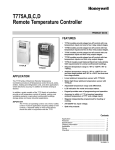
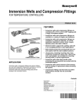
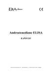
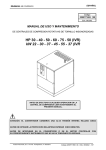
T775J
Electronic Remote Temperature Controller
PRODUCT DATA
FEATURES
GENERAL
The T775J family of electronic remote temperature controllers
provides reset control for chillers, heating and cooling
systems, and other applications where electronic accuracy in
addition to remote sensing is desired.
• T775 model provides reset control with two
temperature inputs and one of either 4 to 20 mA, 0 to
18 Vdc, or Electronic Series 90a Proportional + Integral
modulating output with 0 or 1 relay output stages, or 1
or 2 relay output stages with no modulation.
• -40°F to +220°F (-40°C to +105°C) setpoint temperature
range.
• -45°F to +225°F (-43°C to +107°C) sensor display
range.
• -30°F to + 140°F (-34°C to +60°C) ambient temperature
range.
• Linear platinum temperature sensor.
• Adjustable temperature range and differential.
• Adjustable throttling range of 2° to 30° F or C.
• Adjustable reset ratio.
• Liquid crystal display (LCD) indication for mode and
output status.
• Keypad provides ease of programming and
operation.
• Accuracy is within +/- 1°F/C at nominal input voltage,
nominal sensor ambient temperature (77°F (25°C)
operating ambient). Accuracy can vary as parameters
deviate from nominal.
• Stages independently programmed for heating or
cooling.
• 24/120/240 Vac voltage inputs.
• Spdt relay outputs.
IMPORTANT
The T775 is an operating control, not a limit or safety
control. When used in applications requiring safety
or limit controls, use a separate safety or limit control
device in conjunction with the T775.
a The Electronic Series 90 output provided with T775J
models will not drive electromechanical Series 90 slidewire
devices.
Contents
General ...............................................................................
Features ..............................................................................
Specifications ......................................................................
Ordering Information ...........................................................
Installation ...........................................................................
Description/Operation .........................................................
Checkout .............................................................................
Copyright © 1995 Honeywell Inc. • All Rights Reserved
1
1
2
2
3
13
18
63-2248-4
T775J ELECTRONIC REMOTE TEMPERATURE CONTROLLER
Electrical Ratings:
Voltage Input: 24/120/240 Vac, 50/60 Hz (+10/-15%).
Power Consumption:
50 Hz: 10 VA maximum.
60 Hz: 8 VA maximum.
SPECIFICATIONS
IMPORTANT
The specifications given in this publication do not
include normal manufacturing tolerances. Therefore,
an individual unit may not exactly match the listed
specifications. Also, this product is tested and
calibrated under closely controlled conditions and
some minor differences in performance can be
expected if those conditions are changed.
Contact Ratings:
1/2 HP: 9.8 FLA, 58.8 LRA at 120 Vac.
1/2 HP: 4.9 FLA; 29;4 LRA at 240 Vac.
125 VA pilot duty at 120/240 Vac.
10A at 24 Vac (resistive).
Models (See Table 1):
The T775J family of electronic remote temperature controls
provides reset control for chillers, heating and cooling
systems, and other applications where electronic accuracy in
addition to remote sensing is desired.
Temperature Accuracy:
±1° F (0.6° C) (at nominal input voltage, 77°F (25°C)
operating ambient, nominal sensor ambient).
Setpoint Adjustment Range:
-40° F to +220° F
(-40° C to +105° C).
T775J provides reset control with two temperature inputs and
one of either 4 to 20 mA, Electronic Series 90, or 0 to 18 Vdc
Proportional + Integral modulating output with 0 or 1 relay
output stages, or 1 to 2 relay output stages with no
modulation. Includes two part number 193987GA
Sensors.
Operating Ambient Temperature:
Controller: -30°F to + 140°F (-34°C to 60°C).
Sensor: -45°F to + 225°F (-43°C to 107°C).
Throttling Range for Modulating Output:
Adjustable 2° to 30° F or C.
Table 1. T775J Model Numbers and Outputs.
Outputs
Model
Number
Modulation
Type
Number of Relay
Outputs
T775J1001
None
1
T775J1019
Series 90
0
T775J1027
4-20 mA
0
T775J1035
0-18 Vdc
0
T775J1043
Series 90
1
T775J1050
4-20 mA
1
T775J1068
0-18 Vdc
1
T775J1076
None
2
Differential Range for Staged Output:
Adjustable 1° to 30° F.
Reset Ratio:
Adjustable between 1 to 30 and 30 to 1.
Operating Humidity:
5 to 95 percent relative humidity, noncondensing.
Sensor:
Positive coefficient platinum type, 4.8 ohms/°F, 1000 feet
maximum distance between sensor and solid state controller
(requires calibration over 400 feet).
Approvals:
Underwriters Laboratories Inc. Listed: File No. E4436.
Guide XAPX.
Canadian Standards Association Certified: File No.
LR47125.
ORDERING INFORMATION
When purchasing replacement and modernization products from your TRADELINE® wholesaler or distributor, refer to the
TRADELINE® Catalog or price sheets for complete ordering number .
1. Model Number
2. Accessory
If you have additional questions, need further information, or would like to comment on our products or services, please write or
phone:
1. Your local Home and Building Control Sales Office (check white pages of your phone directory).
2. Home and Building Control Customer Logistics
Honeywell Inc., 1885 Douglas Drive North
Minneapolis, Minnesota 55422-4386
In Canada—Honeywell Limited/Honeywell Limitée, 35 Dynamic Drive, Scarborough, Ontario M1V 4Z9. International Sales and
Service Offices in all principal cities of the world. Manufacturing in Australia, Canada, Finland, France, Germany, Japan, Mexico,
Netherlands, Spain, Taiwan, United Kingdom, U.S.A.
63-2248—4
2
T775J ELECTRONIC REMOTE TEMPERATURE CONTROLLER
Mounting:
Mounts on any suitable horizontal or vertical surface. (See
Fig. 5 for mounting hole locations.)
CAUTION
Disconnect power before installation to prevent
electrical shock or equipment damage.
Dimensions:
See Fig. 1.
Location and Mounting
Display Resolution:
Sensed temperature and other operating parameters are
displayed via a liquid crystal display (LCD) with a resolution of
1°F or 1°C.
Mount the controller in any convenient interior location using
the two mounting holes provided. Mounting screws are not
included. Use controller dimensions in Fig. 1 as a guide.
Sensor Location
Accessories:
C7100C1003 Duct Mount Averaging Sensor*.
T7047C1090 Wall Mount Sensor Case.
107324A Bulb Holder, duct insertion.
121371A Copper Immersion Well.
121371E Stainless Steel Immersion Well.
107408 Heat Conduction Compound, 4 ounce.
C7043A1098 Case and Immersion Well.
203401B Waterproof Sensor.
203531A Panel Mounting Kit.
A775A1003 Sensor Simulator.
*Use of C7100C1003 decreases accuracy of T775 to ±2°F
(±1°C).
The 193987GA Sensor can be used up to 1000 ft (304m)
from the T775 using standard AWG 18/2 unshielded wire. If
longer than 25 feet in an electrically noisy environment, use
shielded cable. Locate the sensor on pipes, in immersion
wells, in wall-mounted cases or on a bulb holder.
Multiple sensors can be parallel-series wired to sense
average temperature in large spaces. In order to maintain
control accuracy, be sure the number of sensors parallelseries wired is of the n2 power (i.e., 1, 4, 9, 16, etc). See
Fig. 2.
SENSORS
SELECT
SET
ENTER
8-1/2
(216)
5-7/32
(134)
1-1/4
(32)
1-1/4
(32)
3-13/16 (97)
4-3/4 (121)
7/8 (22) DIAMETER
TO T775 CONNECTIONS 1 AND 2 (SENSOR A)
OR 7 AND 8 (SENSOR B).
2-3/8 (60)
M7431
M344C
Fig. 2. Parallel-series wiring of sensors.
Fig. 1. Approximate T775J dimensions in in. (mm).
Sensor Mounting
Mount the sensor on a wall or panel for sensing space
temperature (Fig. 3); strap it to a pipe, or insert it into a well
(Fig. 4) for hot/cold water sensing; or tape it to a standard
cap or bulb holder for duct air sensing. To prevent moisture or
condensation entering the sensor through the leadwire holes,
mount the sensor with leadwires exiting the bottom of the
sensor.
INSTALLATION
When Installing this Product...
쐃 Read these instructions carefully. Failure to follow them
could damage the product or cause a hazardous
condition.
쐇 Check the ratings given in these instructions and on the
product to make sure the product is suitable for your
application.
쐋 Installer must be a trained, experienced service
technician.
쐏 After installation is complete, check out the product
operation as provided in these instructions.
NOTE:
3
Use heat conductive compound in immersion wells.
See Accessories.
63-2248—4
T775J ELECTRONIC REMOTE TEMPERATURE CONTROLLER
Mounting Sensor in T7047C1090 Case
Wiring
쐃 Run wires from T775J through wall.
쐇 Mount case to wall with screws provided.
쐋 Connect wires from the T775J to two T terminals on the
T7047C Case.
� Cut and strip 193987GA Sensor leads to 3 to 4 inch (76
to 102 mm) length and connect to T terminals in the
case.
� Position sensor as shown in Fig. 3; assemble cover and
tighten cover screws.
CAUTION
Disconnect external power before wiring to prevent
electrical shock or equipment damage.
IMPORTANT
The T775J is not intended for safety limit
applications. It is an operating control, not a safety
control.
CAUTION
Disconnect external power before wiring to prevent electrical
shock or equipment damage. All wiring must comply with
applicable local codes and ordinances.
1 . Make sure that metal tube of sensor does not short
against T terminals in wall-mounted case.
2. Do not run sensor wiring (even if using shielded
cable) with building power wiring.
T7047C1090
WALLMOUNT SENSOR
CASE (OPTIONAL)
Refer to Fig. 4 for locating the appropriate power inputs,
remote sensor inputs, relay, modulating output terminals,
contact closure input, and sensor selection switch. Access the
terminals through standard conduit knockouts (A-C) located
around the enclosure perimeter.
193987GA
SENSOR
NOTE: Hole A should only be used for remote sensor
wiring, low voltage wiring, and access to modulating
output.
LEADWIRES
TO T775
SCREW
TERMINAL
When wiring the input power, only one source of power can
be applied to the T775J (e.g., 24 or 120 or 240 Vac).
Knockouts B and C can be used to gain access to 120 or 240
Vac input terminals and the load relay output terminals.
SCREW
TERMINAL
The T775J can be used to provide reset control of damper
and valve actuators that accept 4 to 20 mA, 0 to 18 Vdc or
Electronic Series 90 modulating inputs, and to control one onoff load. Depending on the application and the motor or
actuator used, the T775J can control up to three Modutrol
motors by using resistor kits that are available as accessories
for existing motors. Use specified resistor kits to control an
Electronic Series 90 (Modutrol®) Motor with a 4 to 20 mA
controller. Obtain information on these kits from either the
TRADELINE® catalog, motor specification or your local
distributors. See Fig. 7 through 15 for typical T775J wiring and
applications.
CAUTION: POSITION SENSOR AWAY
FROM SCREW TERMINALS.
M8109C
Fig. 3. Sensor mounted on wall.
COVER SENSOR
LEADS WITH
HEAT CONDUCTIVE
COMPOUND
SENSOR PLACED
IN WELL
1/2 NPT
IMMERSION
WELL
M5249
Fig. 4. Sensor inserted in immersion well.
63-2248—4
4
T775J ELECTRONIC REMOTE TEMPERATURE CONTROLLER
LCD
TEMPERATURE
DISPLAY
C/F
O
SELECT
SET
12 3 4
PROGRAMMING
KEYS
ENTER
SENSOR INPUT,
TOD, AND
24V TERMINALS
SA
SA TOD 24V SB
3 2 1
120V
COM
240V
MODULATING OUTPUT
ELECTRONIC
SERIES 90, 4-20 mA
OR 0-18 VDC
DEPENDING ON MODEL
KNOCKOUT "B"
SB
RESET DIP
SWITCHES
MOUNTING
HOLE
LOCATION
1 2 3 4 5 6 7 8
KNOCKOUT "A"
O
C / F SELECTION
OUTPUT 1
OUTPUT 2
NO COM NC
NO COM NC
LINE
VOLTAGE
INPUTS
KNOCKOUT "C"
RELAY OUTPUT
STAGES
M8118
Fig. 5. Feature locations.
IMPORTANT
Erratic temperature readings from the 193987GA
Sensor can be caused by poor wiring practices that
must be avoided to assure proper operation:
a. Do not route temperature sensor wiring with
building power wiring.
b. Do not locate temperature sensor wiring next to
control contactors.
c. Do not locate temperature sensor wiring near
electric motors.
d. Do not locate temperature sensor wiring near
welding equipment.
e. Make sure good mechanical connections are
made to both the sensor and the controller.
f. Do not mount sensor with leadwire end (wire end)
pointing up in an area where condensation can
occur.
g. Use shielded wiring to connect the sensor to the
T775 when an electrically noisy environment
exists. See Fig. 6.
T775
C/F
12 3 4
SET
SELECT
ENTER
GROUND
SHIELD
TO T775
CASE OR TO
GROUNDING
SCREW
SA
SB
1 2 3 4 5 6 7 8
SHIELDED
CABLE
SA TOD 24V SB
3 2 1
120V
COM
240V
SHIELDED
CABLE
OUTPUT 1
OUTPUT 2
NO COM NC
NO COM NC
NOTE: DO NOT GROUND
SHIELDED CABLE AT
SENSOR END.
GROUNDING SCREW
SENSOR
NOTE: TO MINIMIZE NOISE PICKUP, MAKE CONNECTION
FROM SHIELDED CABLE AS CLOSE AS POSSIBLE
TO SENSOR BODY.
M4718
Fig. 6. Using shielded cable for cable
runs longer than 25 feet.
5
63-2248—4
T775J ELECTRONIC REMOTE TEMPERATURE CONTROLLER
C/F
SET
SELECT
12 3 4
C/F
ENTER
SA
SET
1234
SELECT
ENTER
SA
SENSOR A
24 VAC
SENSOR B
SB
SB
SENSOR A
1 2 3 4 5 6 7 8
SENSOR B
SA TOD 24V SB
3 2 1
1 2 3 4 5 6 7 8
120V
COM
240V
SA TOD 24V SB
3 2 1
120V
COM
240V
BLK
OUTPUT 1
OUTPUT 2
NO COM NC
NO COM NC
240 VAC
RED
LOAD 1
LOAD 2
OUTPUT 1
OUTPUT 2
NO COM NC
NO COM NC
LOAD 1
M8111
LOAD 2
Fig. 7. Reset control with 24 Vac input,
24 Vac loads.
M8113
Fig. 9. Reset control with 240 Vac input, 240 Vac loads.
C/F
C/F
ENTER
SA
SET
SELECT
ENTER
SA
SB
SENSOR A
1 2 3 4 5 6 7 8
SENSOR A
1 2 3 4 5 6 7 8
SENSOR B
SA TOD 24V SB
3 2 1
SENSOR B
SA TOD 24V SB
3 2 1
120V
COM
240V
120V
COM
240V
OUTPUT 2
NO COM NC
NO COM NC
120 VAC
OUTPUT 1
OUTPUT 2
NO COM NC
NO COM NC
120 VAC
WHT
WHT
LOAD 1
LOAD 1
LOAD 2
LOAD 2
24 VAC
M8114
M8112
Fig. 10. Reset control with 120 Vac input, 24 Vac loads.
Fig 8. Reset control with 120 Vac input, 120 Vac loads.
63-2248—4
SB
BLK
BLK
OUTPUT 1
12 34
12 34
SET
SELECT
6
T775J ELECTRONIC REMOTE TEMPERATURE CONTROLLER
ELECTRONIC SERIES 90
MODUTROL MOTOR
C/F
B R W
SELECT
SET
12 3 4
T1 T2
ENTER
SA
SENSOR A
24 VAC
SENSOR B
POWER
INPUT
SB
1 2 3 4 5 6 7 8
SA TOD 24V SB
3 2 1
B R W
1
120V
COM
240V
LOAD 1
OUTPUT 2
NO COM NC
T775J
1
USE SEPARATE TRANSFORMER FOR T775 WHEN POWERING FROM 24 VOLTS.
NOTE: T775J1019, T775J1043 PROVIDE ELECTRONIC SERIES 90 OUTPUT THAT
WILL NOT DRIVE 135 OHM SLIDEWIRE DEVICES.
PROPER OUTPUT LEVELS CAN BE CHECKED BY MEASURING THE OPEN CIRCUIT VOLTAGE
BETWEEN TERMINALS 1 (W) AND 2 (R):
MINIMUM (DRIVE CLOSED): ≤ 0.17 VDC
M8115A
MAXIMUM (DRIVE OPEN): ≥ 1.7 VDC
Fig. 11. Reset control with 24 Vac input, Series 90 and 24 Vac loads.
4-20mA MODULATING
MOTOR OR ACTUATOR
C/F
12 34
T1 T2
_ +
SELECT
SET
ENTER
SA
SENSOR A
1 2 3 4 5 6 7 8
SENSOR B
SA TOD 24V SB
3 2 1
POWER
INPUT
SB
- +
120V
COM
240V
BLK
120 VAC
OUTPUT 2
WHT
NO COM NC
LOAD 1
M8116
Fig. 12. Reset control with 120 Vac input, 4 to 20 mA and 120 Vac loads.
7
63-2248—4
T775J ELECTRONIC REMOTE TEMPERATURE CONTROLLER
MODULATING MOTOR WITH
VOLTAGE CONTROL INPUT
C/F
C R
F
SET
SELECT
12 3 4
T1 T2
ENTER
SA
SENSOR A
1 2 3 4 5 6 7 8
SENSOR B
SA TOD 24V SB
3 2 1
POWER
INPUT
SB
- +
120V
COM
240V
BLK
240 VAC
OUTPUT 2
RED
NO COM NC
LOAD 1
M8117
Fig. 13. Reset control with 240 Vac input, 240 Vac and 0 to 18 Vdc loads.
1
L2
L1
(HOT)
M954 OR M955
MODUTROL® MOTOR
DIP SWITCHES
FOR SENSOR TO
LOAD SELECTION.
R
TR
C/F
W
2
B
12 3 4
SELECT
SET
ENTER
SA
TR
SB
M954 OR M955
MODUTROL® MOTOR
1 2 3 4 5 6 7 8
R
SA TOD 24V SB
3 2 1
TR
W
TR
B R W
B
120V
COM
240V
OUTPUT 1
OUTPUT 2
NO COM NC
NO COM NC
M954 OR M955
MODUTROL® MOTOR
R
TR
W
TR
NOTE:
USE SEPARATE TRANSFORMER FOR T775 WHEN POWERING FROM 24 VAC.
B
1
POWER SUPPLY. PROVIDE DISCONNECT MEANS AND OVERLOAD PROTECTION AS REQUIRED.
2
USE 1300 OHM RESISTOR FOR 2 MOTORS, 910 OHMS RESISTOR FOR 3 MOTORS. 4047EAU RESISTOR KIT
(SHIPPED WITH M954, M955 MOTORS) INCLUDES 1300 OHM AND 910 OHM RESISTORS.
Fig. 14. Reset control with Series 90 Modutrol® Motor.
63-2248—4
8
M4717
T775J ELECTRONIC REMOTE TEMPERATURE CONTROLLER
DIP SWITCHES
FOR SENSOR TO
LOAD SELECTION.
ML984 ACTUATOR
C/F
B
R
12 3 4
T1 T2
W
SELECT
SET
ENTER
SA
SB
1 2 3 4 5 6 7 8
SA TOD 24V SB
3 2 1
250 OHM
B R W
POWER
INPUT
120V
COM
240V
1
1
POWER SUPPLY. PROVIDE DISCONNECT MEANS AND
OVERLOAD PROTECTION AS REQUIRED.
OUTPUT 1
OUTPUT 2
NO COM NC
NO COM NC
M4716
Fig. 15. Reset control with ML984 Valve Actuator.
Use shielded cable if any of the above conditions cannot be
avoided.
CAUTION
Device Setup
The T775J will not allow the user to program for both
heating and cooling loads to be energized at the same
time.
쐃 Determine the loads to be controlled and the operating
mode (heat or cool) and enter on the worksheet.
If this situation results, cooling loads will be energized
and heating loads will be prevented from also
energizing. The number (1,2) of these nonenergized
loads will flash, along with the word HEAT, to indicate
a call for both heating and cooling loads controlled by
one sensor has occurred and to alert the user to
reprogram the affected control values.
For example: Load 1: Compressor 1 (cool)
Setpt 1 _____
On at _____
Diff 1 _____
Off at _____
쐇 Determine the setpoint (Setpt) and the switching
differential (Diff) temperatures for each on/off load and
enter on the worksheet.
쐏 To calculate the Reset Ratio to be used, determine the
number of degrees the setpoint for the control sensor A
should be reset (Reset Ratio A Value) to compensate
for a change in the reset compensation sensor B (Reset
Ratio B Value). Enter the values on the Device
Programming Worksheet (values should be whole
numbers from 1 to 30).
For example: Load 1: Compressor 1 (cool)
Setpt 1 78°F
On at 82°F
Off at 78°F
Diff 1 4°F
쐋 Refer to the Control Algorithm section to calculate the
load on and off temperatures and enter on the
worksheet. Remember that on/off outputs are off at
setpoint in both the heating and cooling operating
modes. When in cooling mode, the load will be turned
on at setpoint plus the differential. When in heating
mode, the load will be turned on at setpoint minus the
differential.
CAUTION
A reset ratio lower than one can result in unstable
control. Widening the throttling range and/or
differential will minimize this effect.
9
63-2248—4
T775J ELECTRONIC REMOTE TEMPERATURE CONTROLLER
쐄 To avoid this time delay, press Select.
쐂 Press Select and Enter keys simultaneously to begin
programming the load operating mode (heat or cool).
The display will indicate heat or cool and the stage
number.
쐆 Press Set (down arrow) to change to cooling. Set (up
arrow) will change back to heating.
쐊 Press Enter to program the displayed mode into
memory.
쐎 Press Select to go to the next step.
쐅 Repeat steps 6 through 8 for additional changes.
쐄 Determine the desired Reset Direction (up or down)
and enter on the Device Programming Worksheet. This
will determine if the setpoint for the control Sensor A
will be reset up or down.
쐂 Determine the desired Reset Compensation Setpoint
for Sensor B. Enter the value on the Device
Programming Worksheet.
쐆 Determine whether the desired Reset Action should
occur above or below the Reset Compensation
Setpoint. Enter above or below on the Device
Programming Worksheet.
쐊 Remove the T775J cover and enter the values listed on
the worksheet and the date in the first column on the
label inside the T775J cover.
Programming Stage Control Values
쐃 If you have a 0 to 18 Vdc output T775J, go to the
Calibration Procedure for 0 to 18 Vdc Output T775
before continuing to program the stage control values.
The Series 90 and 4-20 mA output T775J Controller
does not require calibration, so proceed to step 2.
Device Programming Worksheet
Load 1:
Setpt 1 ___________
On at __________
Diff 1 or Throttling Range __ Off at __________
Load 2:
Setpt 2 ___________
Diff 2 ____________
IMPORTANT
When programming all stages ,it is important to note
that the first stage designated on the LCD display is
always the modulating output.
On at __________
Off at __________
Reset Ratio:
Reset Ratio B Value ______
Reset Ratio A Value ______
쐇 Press Select to display the current stage setpoint.
쐋 Press Set (up arrow) to increase or Set (down arrow) to
decrease the display to the desired setpoint.
쐏 Press Enter to enter the displayed value into memory.
쐄 Press Select to display the current stage throttling
range or switching differential.
쐂 Press Set (up arrow) to increase or Set (down arrow) to
decrease the display to the desired throttling range or
switching differential.
쐆 Press Enter to enter the displayed value into memory.
쐊 Repeat steps 2 through 7 to program each additional
stage.
Reset Direction __________________________
Compensation Setpoint Sensor B ____________
ResetAction _____________________________
Device Programming
Factory Default Values
When power is initially applied to the T775J, the control points
will be at the factory set default values. Default values are:
Stage
Setpoint
Differential/
Throttling Range
Operating
Mode
Stage 1
72°F
2°F
Heat
Stage 2
70°F
2°F
Heat
IMPORTANT
After initial programming, altering the setpoint up or
down for stage 1 will result in a change in setpoint 2
by the same number of degrees and in the same
direction. If increasing or decreasing the setpoint for
stage 1 results in exceeding the control limits (-40°F
to +220°F) for stage 2, the control will not allow the
user to enter a value for stage 1 higher or lower than
this limit. This will allow for easy sequential output
staging to be modified while keeping the margin
intact between setpoints.
쐃 Set the reset direction determined previously by setting
the DIP switch in the upper right corner of the T775
(see Fig. 5). Switch 1 should be open to reset the
control point up and closed to reset the control point
down.
쐇 Set the reset action determined previously by setting
the DIP switch in the upper right corner of the T775J.
Switch 2 should be open if the reset is to occur when
the outdoor temperature is below the reset
compensation setpoint and closed if the reset is to
occur when the outdoor air temperature is above the
reset compensation setpoint.
쐋 Before programming the T775J, verify that the °F/°C
selection jumper is properly installed. The T775J is
shipped from the factory with the jumper installed in the
°F position. If °C is desired, remove the jumper.
쐏 Apply power to the device. The device will begin
counting down from 210. This countdown sequence will
last for approximate 3-1/2 minutes.
63-2248—4
Programming Reset Values
쐃 Press Select to display the current reset compensation
setpoint (Sensor B).
쐇 Press Set (up arrow) to increase or Set (down arrow) to
decrease the display to the desired setpoint.
쐋 Press Enter to enter the displayed value into memory.
쐏 Press Select to display the current Reset Ratio B
value.
쐄 Press Set (up arrow) to increase or Set (down arrow) to
decrease the display to the desired Reset Ratio B
value.
쐂 Press Enter to enter the displayed value into memory.
쐆 Press Select to display the current Reset Ratio A.
쐊 Press Set (up arrow) to increase or Set (down arrow) to
decrease the display to the desired Reset Ratio A
value.
10
T775J ELECTRONIC REMOTE TEMPERATURE CONTROLLER
쐎 Press Enter to enter the displayed value into memory.
쐅 Press Select four times to return to stage 1 parameters.
Scroll through the programming loop a second time to
confirm that the appropriate values have been entered
into memory.
Calibration Setpoint for Cooling Mode (Fig. 13)
Setpoint for calibrating the lower voltage level (closed
position):
A
B
Sensed Temperature
78°
Add 3° F or C to above:
+3°
Calibration Setpoint:
81°
NOTE: The T775J has three options for displaying the
sensed temperatures:
1. Sensor A only.
2. Sensor B only.
3. Alternating between Sensor A and Sensor B.
Calibration Setpoint for Heating Mode:
Sensed Temperature:
Subtract 3° F or C from above:
Calibration Setpoint
쐈 Press Select after viewing the switching differential for
the final stage to display Sensor A temperature only.
쐉 Press Select again to display Sensor B temperature
only.
씈 Press Select again to alternate the display between
Sensor A temperature and Sensor B temperature at
approximately five second intervals.
씉 Before replacing the cover on the T775J, check to see
that the control values have been recorded on the label
on the back of the cover.
NOTE:
B
Calibrate the Lower Voltage Level (Closed Position).
쐃 Read displayed temperature of sensor that is controlling
stage 1.
쐇 Press Select until the setpoint for stage 1 is displayed.
쐋 If stage 1 is in the HEAT mode, press Set (down arrow)
until the setpoint is at least three degrees below the
temperature in step 1.
쐏 If stage 1 is in the COOL mode, press Set (up arrow)
until the setpoint is at least three degrees above the
temperature in step 1.
쐄 Press Enter to enter this value into memory.
쐂 Press Select once so that the throttling range is
displayed.
쐆 Press Set (up arrow) or Set (down arrow) until the
throttling range is two degrees.
쐊 Press Enter to enter this value into memory.
쐎 Connect voltmeter as shown in Fig. 8.
쐅 Press Select until Sensor A is displayed (if the sensed
temperature has drifted from step 1, you may need to
repeat steps 2 through 8).
쐈 Turn the zeroing voltage potentiometer with a
screwdriver until the desired lower voltage (i.e., 2V, 6V,
etc) is displayed on the voltmeter.
쐉 Confirm upper voltage level:
•
Record the sensed temperature for sensor
controlling stage 1.
•
Press Select until stage 1 setpoint is displayed.
•
If stage 1 is in the HEAT mode, press Set (up
arrow) until setpoint is at least three degrees
above the sensed temperature.
•
If stage 1 is in the COOL mode, press Set (down
arrow) until setpoint is at least three degrees
below the sensed temperature.
•
Press Enter to enter this value into memory.
•
Record the (desired) upper voltage level.
•
If the value is not correct, make sure the correct
span switch is depressed and the stage is in the
correct mode of operation (HEAT or COOL).
Verify which sensor is controlling stage 1.
씈 Rotate the display printed wiring board back into the
device and tighten the screw in the upper right corner.
씉 Disconnect the voltmeter from the modulating outputs
and connect the load to the plus and minus terminals of
the modulating terminal block.
씊 Return to Programming Stage Control Values to enter
the desired stage control values.
The control values programmed into memory will not
be lost because of a power failure.
Calibration Procedure for 0 to 18 Vdc Output T775J
NOTE:
A
78°
-3°
75°
The 0-18 Vdc Output T775J models have field
selectable starting voltages and spans and will
require calibration. The Series 90 and 4-20 mA
output devices require no calibration.
쐃 Disconnect power to the device.
쐇 Remove the device cover and disconnect the load from
the plus and minus outputs. Connect a dc voltmeter to
the plus and minus modulating outputs of the T775J
(see Fig. 12).
쐋 Loosen the screw in the upper right corner of the T775J
approximately six turns with a screwdriver (see
Fig. 12).
쐏 Rotate the display printed wiring board outward from
the device until it is approximately perpendicular to the
enclosure (see Fig. 12).
쐄 The T775 is factory set to a span of 8 Vdc. To select a
different span (3 Vdc, 14 Vdc, or 17 Vdc), change the
switch positions on the voltage selection switch by
opening the switch for 8 Vdc and closing the switch for
the chosen span (see Fig. 12).
쐂 Apply power to the device.
쐆 Press Select until Sensor A temperature is displayed.
쐊 Record the sensed temperature.
쐎 Determine the operating mode for stage 1 (Heat or
Cool). Choose the appropriate example to follow.
Calculate the setpoints to be used for calibrating the
device in column B, following the example in column A.
11
63-2248—4
T775J ELECTRONIC REMOTE TEMPERATURE CONTROLLER
STEP 1
STEP 2
VOLTAGE SPAN
SELECTION SWITCH
ZEROING
VOLTAGE DIAL
1 2 3 4
SET
1 2 34
SELECT
ENTER
SA
OPEN
3 8 14 17
SB
1 2 3 4 5 6 7 8
SA TOD 24V SB
3 2 1
3 2 1
MODULATING
VOLTAGE
OUTPUT
120V
COM
240V
120V
COM
240V
SENSOR INPUT,
TOD, AND
24 VAC
TERMINALS
OUTPUT 1
OUTPUT 2
OUTPUT 1
OUTPUT 2
NO COM NC
NO COM NC
NO COM NC
NO COM NC
GENTLY PULL THE TOP PWB UPWARDS AROUND
ITS HINGE. STOP WHEN THE PWB IS
PERPENDICULAR TO THE ENCLOSURE.
REMOVE FRONT COVER AND LOOSEN SCREW
IN UPPER RIGHT CORNER OF DEVICE WITH A
SCREWDRIVER.
1
2
3
4
O
P
E
N
CLOSED
STEP 3
OPEN
3 8 14 17
VOLTAGE SPANS
1 2 3 4
WHEN SWITCH IS DEPRESSED, THE
VOLTAGE RANGE IDENTIFIED BY
THE VOLTAGE SPAN BELOW THAT
SWITCH IS SELECTED. IN THIS
CASE, A VOLTAGE SPAN ON 8 VDC
HAS BEEN SELECTED. THIS SPAN
CAN BE 2-10 VDC, 10-18 VDC, ETC.,
BY USE OF ZEROING DIAL.
OPEN
3 8 14 17
VOLTMETER
3
2 1
18
0
120V
COM
240V
OUTPUT 1
OUTPUT 2
NO COM NC
NO COM NC
-
CONNECT THE MODULATING VOLTAGE OUTPUT
TO A VOLTMETER. USING A SCREWDRIVER,
ADJUST THE LOWER LIMIT OF THE VOLTAGE TO THE
DESIRED LEVEL ACCORDING TO THE STEPS
OUTLINED IN CLAIBRATION PROCEDURE FOR
0 TO18 VDC OUTPUT.
M1345B
Fig. 16. Voltage span selection.
63-2248—4
+
12
T775J ELECTRONIC REMOTE TEMPERATURE CONTROLLER
HEATING MODE
MODULATION
SENSED
o
TEMPERATURE = 78 F
DEAD BAND
THROTTLING
RANGE
CALIBRATION
SETPOINT 75oF
MODULATION
* DEADBAND IS 1/8 OF THE THROTTLING RANGE
COOLING MODE
CALIBRATION
o
SETPOINT 81 F
MODULATION
SENSED
o
TEMPERATURE = 78 F
DEAD BAND
THROTTLING
RANGE
MODULATION
* DEADBAND IS 1/8 OF THE THROTTLING RANGE
M2149C
Fig. 17. Explanation of calibration setpoints for heating and cooling modes.
the modulating output will be designated as stage 1 on the
LCD display. Although the modulating output is designated as
stage 1, it can be programmed to energize after the second
stage is energized.
DESCRIPTION/OPERATION
Control Algorithm
Reset Control
The T775J offers four different reset configurations and an
adjustable reset ratio between 30 to 1 and 1 to 30.
The T775J operates as a reset controller with two sensor
inputs. The outdoor sensor is designated Sensor B and the
control medium sensor is Sensor A. Sensor B is wired to pins
7 and 8 of the input terminal block, while Sensor A is wired to
pins 1 and 2. The T775J is capable of providing modulating or
relay outputs for reset control. Each stage of the T775J has its
own independent setpoint that can be configured to operate in
the cooling or heating mode. The mode of operation for each
stage is user determined by the programming keys.
The reset ratio expresses the amount of change in the
heating or cooling medium control point caused by a change
in the outdoor temperature. It is the ratio of outdoor
temperature change to heating or cooling control point
change (Sensor B/Sensor A). The reset ratio can be an
inverse ratio (when the outdoor temperature goes down, the
control point goes up) or a direct ratio (when the outdoor
For reset control with two outputs, one of which is modulating,
13
63-2248—4
T775J ELECTRONIC REMOTE TEMPERATURE CONTROLLER
RESET DIRECTION SWITCH
temperature goes down, the control point goes down). The
type of ratio is selected by using the two DIP switches
provided.
1
2
The four possible reset operating configurations are illustrated
and explained in Fig. 18. Switches 1 and 2 are shown but
switches 3 and 4 are unused; however, the location of these
DIP switches is shown in Fig. 5.
OPEN
CLOSED
A reset ratio lower than one can result in unstable
control. Widening the throttling range and/or
differential minimizes this effect.
RESET ACTION SWITCH
RESET ACTION SWITCH: RESET IF THE
OUTDOOR TEMPERATURE (SENSOR B) IS
ABOVE (WHEN CLOSED) OR BELOW
(WHEN OPEN) THE OUTDOOR
TEMPERATURE SETPOINT.
SWITCH
SWITCH
CAUTION
RESET DIRECTION SWITCH: WILL RESET
THE COUNTROL POINT UP (WHEN
OPEN) OR DOWN (WHEN CLOSED).
PWB
OPEN
PWB
CLOSED
SIDEVIEW
Proportional + Integral Modulating Control
RESET DIRECTION SWITCH OPEN
1
Proportional + Integral (P+I) control provides fast, responsive
operation of the controlled devices in reacting to temperature
changes by providing an output signal proportional to the
deviation between setpoint and actual temperature. An
integral proportion also provides a time dependent output
signal that is dependent on the length of time of the deviation
between actual set point and sensed temperature.
2
IF THE OUTSIDE SENSOR (B)
TEMPERATURE IS BELOW THE OUTSIDE
TEMPERATURE SETPOINT,THE CONTROL
POINT WILL BE INCREASED BY THE
RESET RATIO.
RESET ACTION SWITCH OPEN
OPEN
CLOSED
1
The P + I algorithm places the control setpoint in the middle
of the throttling range. A deadband around setpoint exists and
is proportional to the throttling range. For the T775, this
deadband is 1/8 of the throttling range.
2
RESET DIRECTION SWITCH CLOSED
IF THE OUTSIDE SENSOR (B)
TEMPERATURE IS BELOW THE OUTSIDE
TEMPERATURE SETPOINT,THE CONTROL
POINT WILL BE DECREASED BY THE
RESET RATIO.
RESET ACTION SWITCH OPEN
OPEN
There are three modulation options available for the T775J
(see Fig. 20 for modulating output connecting terminals).
CLOSED
Fig. 18. Reset switch configuration.
1
2
RESET DIRECTION SWITCH OPEN
IF THE OUTSIDE SENSOR (B)
TEMPERATURE IS ABOVE THE OUTSIDE
TEMPERATURE SETPOINT,THE CONTROL
POINT WILL BE INCREASED BY THE
RESET RATIO.
RESET ACTION SWITCH CLOSED
OPEN
CLOSED
1
2
RESET DIRECTION SWITCH CLOSED
IF THE OUTSIDE SENSOR (B)
TEMPERATURE IS ABOVE THE OUTSIDE
TEMPERATURE SETPOINT,THE CONTROL
POINT WILL BE DECREASED BY THE
RESET RATIO.
RESET ACTION SWITCH CLOSED
OPEN
CLOSED
M8110A
Fig. 19. Summary of action/direction switches.
63-2248—4
14
T775J ELECTRONIC REMOTE TEMPERATURE CONTROLLER
SETPOINT "B" (OUTSIDE TEMPERATURE)
BELOW
1
ABOVE
A
C
2
B
D
B
D
RESET DIRECTION
SWITCH
RESET ACTION
SWITCH
3
3
OPEN
2
OPEN
RESET ACTION
SWITCH
A
C
1
RESET DIRECTION
SWITCH
4
4
RESETS CONTROL SETPOINT A UP
WHEN SENSOR B (OUTSIDE
TEMPERATURE) IS ABOVE SETPOINT.
DOWN
UP
RESETS CONTROL SETPOINT A UP
WHEN SENSOR B (OUTSIDE
TEMPERATURE) IS BELOW SETPOINT.
RESETS CONTROL SETPOINT A DOWN
WHEN SENSOR B (OUTSIDE
TEMPERATURE) IS ABOVE SETPOINT.
RESETS CONTROL SETPOINT A DOWN
WHEN SENSOR B (OUTSIDE
TEMPERATURE) IS BELOW SETPOINT.
1
2
A
C
B
D
B
D
RESET DIRECTION
SWITCH
RESET ACTION
SWITCH
3
3
OPEN
2
OPEN
RESET ACTION
SWITCH
A
C
1
RESET DIRECTION
SWITCH
4
4
A. SWITCH 1 CONTROLS THE RESET DIRECTION.
LEFT RESETS SENSOR A CONTROL POINT (BOILER OR CHILLER WATER TEMPERATURE UP;
RIGHT RESETS IT DOWN.
B. SWITCH 2 CONTROLS THE RESET ACTION.
LEFT RESETS AS SENSOR B (OUTDOOR TEMPERATURE) DROPS BELOW SETPOINT B;
RIGHT RESETS AS IT RISES ABOVE IT.
M4719
C. SWITCHES 3 AND 4 ARE NOT USED.
• 4-20 mA: This is a general purpose current mode output that can drive a 600 ohm maximum load without output current
15
63-2248—4
T775J ELECTRONIC REMOTE TEMPERATURE CONTROLLER
A second set of DIP switches provides voltage range
selection for 0 to 18 Vdc modulating devices. The span
corresponding to each switch is given on the printed wiring
board below each switch. Fig. 16 shows the location of this
switch, the zeroing dial, and how to set the voltage span. See
Fig. 19 for a summary of action/direction switches.
degradation. This modulation output can be used with
Honeywell Inc Modutrol IVTM Motors that accept an input
signal of 4-20 mA or other Honeywell Inc motors with the
use of resistor kits.
• 0-18 Vdc (voltage ranging): This output mode is intended
as a general purpose voltage output capable of driving a
2 kohm load minimum. The span of voltage output is user
selectable via a DIP switch (see Fig. 14). The spans
offered are 3, 8, 14 and 17 volts. A zero adjustment dial is
provided to allow the user to select common ranges such
as 4-7 Vdc, 6-9 Vdc, 2-10 Vdc, 10.5 -13.5 Vdc, 14.5-17.5
Vdc, 1-15 Vdc, and 1-18 Vdc. This modulation output can
be used with Modutrol IV™ Motors that accept a voltage
span comparable to any of the above. The device is factory
set at the 2 to 10 Vdc span.
Keypad Programming and Display
The T775J uses a liquid crystal display (LCD) for interactive
prompting during programming and display of sensed
temperatures and assigned setpoint and differential values.
User programming of the T775J is through four programming
keys.
3
2
1
B
R
W
(SERIES 90)
-
+
(4-20 mA AND 0-18 Vdc)
Heat Operation Mode
• Throttling range is centered around the setpoint.
• Modulating outputs are at the minimum or closed position
at setpoint plus one-half of the throttling range.
• Modulating outputs are at the maximum or open position
at setpoint minus one-half of the throttling range.
• Relay outputs are energized at setpoint minus differential
and de-energized at setpoint.
M2133A
Fig. 20. Modulating output terminals.
Cooling Operation Mode
Programming Keys
• The throttling range is centered around the setpoint.
• Modulating outputs are at the minimum or closed position
at setpoint minus one-half of the throttling range.
• Modulating outputs are at the maximum or open position
at setpoint plus one-half of the throttling range.
• Relay outputs are energized at setpoint plus differential
and de-energized at setpoint.
The four programming keys are Select, Up arrow, Down
arrow and Enter.
• Select key sequentially prompts the user for what
parameter is being displayed: setpoint, differential, stage
energized, heat or cool (operation mode), 1, 2 (indicating
assigned stage). Once the last parameter value is viewed,
pressing the Select key will again display the control
values from the beginning of the display loop.
• Up and Down arrow keys allow the displayed parameters
to be increased or decreased. After pressing the Select
key, a control value can be changed by using the arrow
keys. Control values will be increased or decreased by
1° F or C each time the arrows are depressed.
• Enter key places the new value into the memory of the
microprocessor. A control value or operation will not be
effective in the memory until the Enter key is depressed.
Control values and operation selection will remain in the
device memory even after power is removed.
• The Select and Enter keys must be pressed
simultaneously to change the control algorithm from
heating to cooling or from cooling to heating. These
parameters (heat and cool) are not displayed during
normal Select key sequences. The only parameters
displayed after pressing the Select and Enter keys at the
same time are stage indication and Heat or Cool. To
change the operation from heating to cooling or vise versa
for a desired output stage, use the arrow keys as required.
Once the mode is changed, depressing the Enter key is
necessary to enter this change into the microprocessor
memory. The next stage of heat or cool assignment will
appear after the Select key is pressed. When all stages are
selected, the display will revert back to sensed
temperature and load energized status.
Contact Closure Override Input
A two terminal input is provided to allow the user to override a
relay energized condition of all outputs. When used with
modulating devices, a contact closure override input causes
the output to return to its minimum position. This function is
generated by a contact closure between terminal pins 3 and 4
of the terminal block for sensor input shown in Fig. 4. This can
be achieved manually or by using an EMS controller or time
clock with normally open contacts; i.e., W7505, S7005.
When contact closure override is active, the display will show
the number of stages that would have been energized and
“STAGE ENERGIZED’’ will flash.
°F/°C Selection
A single jumper plug controls °F/°C indication of the displayed
temperature value. The location of this jumper is shown in Fig.
5. The unit is shipped with the jumper installed in the °F
mode. Remove the jumper plug for the °C mode. Remove and
reapply power if the jumper is removed with the device
powered.
DIP Switch Selections
DIP switches, see Fig. 18, are provided for assignment of the
reset configurations.
63-2248—4
16
T775J ELECTRONIC REMOTE TEMPERATURE CONTROLLER
The device hardware was configured to a nonexistent
device. This error cannot be field repaired. Replace
the device.
OE—ROM Error.
The internal ROM of the microprocessor is defective.
This error cannot be field repaired. Replace the
device.
AE—RAM Error
The internal RAM of the microprocessor is defective.
This error cannot be field repaired. Replace the
device.
Display
Once power is applied or restored to the device, the display
will count down from 210 until the display reads zero, during
which time any previously energized outputs will be deenergized. This is intended to protect compressors in the
event of a power outage.
To avoid viewing this entire countdown, press the Select key.
The LCD display will now show what it normally reads: load
(sensed) temperature, stages energized, and which Sensor
(A or B) is being read. At any time during the programming or
review procedure, the display will revert back to showing the
sensed temperature and stage status indication 60 seconds
after the last key closure.
Setpoint Calibration
To maintain temperature accuracy, sensor wires should be 18
AWG two-conductor (18/2). If the length of the sensor wire
exceeds 400 feet, recalibration will be necessary to maintain
accuracy (see Fig. 21). Table 2 shows the corresponding
temperature offset that should be used for different sensor
wire lengths. This temperature offset should be added to the
desired temperature setpoint for these applications.
The user has three display options to select. The display can
be configured to alternately indicate Sensor A and Sensor B
sensed temperature at a five second rate or the display can
be locked on to sensor A or sensor B to sense temperature
continuously.
This selection is accomplished by stopping at Sensor A or
Sensor B sensed temperature points in the Select key
scrolling loop. To lock on to either sensor, the user must scroll
the Select key through the loop to select the sensed
temperature prompt desired. The display will stick to that
parameter until the Select key is activated to advance the
loop. When the loop is stopped at any other prompt, the
display will alternately indicate Sensor A and Sensor B
sensed temperatures after 60 seconds from the last key
closure or immediately after the Select key is pressed at the
end of the programming sequence.
RESISTANCE
(OHMS)
4200
4000
3800
3600
3484 ± 6.5 OHMS
AT 77°F (25°C)
3400
Error Messages
There are seven error messages that can be displayed in
response to software or hardware problems with the T775J.
The error codes that may be seen flashing on the display are:
SF—Sensor Failure.
The display flashing SF indicates an out-of-range
sensor. Make sure the sensors are properly
connected. For the T775J, stage 2 load will be deenergized when this error message is flashing for
Sensor B. When this message is flashing for Sensor
A only, stage 1 will not be de-energized.
EF—EEPROM Failure.
The values read back from the EEPROM are not the
same as written into the EEPROM. The EEPROM is
not intended for field repair. Replace the device.
CF—Calibration Failure.
A calibration resistor reading was not within the range
of the Analog to Digital converter. This error message
can not be field repaired. Replace the device.
OF—Stray interrupt Failure.
An unused interrupt occurred. This error cannot be
field repaired. Replace the device.
CE—Configuration Error.
3200
20
60
40
80
100
120
140
160
180
F
220
200
C
-7
0
10
20
40
50
30
60 70
TEMPERATURE (DEGREES)
80
100
90
M2829
Fig. 21. Resistance versus temperature
performance characteristics.
Table 2. Sensor Wire Length/Calibration Offset
(Using 18 Awg Wire).
17
Sensor Wire Length (ft)
Calibration Offset (°)
0-399
None required.
400-599
1
600-799
2
800-1000
3
63-2248—4
T775J ELECTRONIC REMOTE TEMPERATURE CONTROLLER
g.
Divide Reset Ratio B value by Reset Ratio A
value.
h. Multiply the result in step g. by Temp Diff
(step a.).
i.
If Reset Direction Switch is set to increase,
disregard any negative signs and add the amount
of reset calculated in step h. to the on/off values.
j.
If the Reset Direction Switch is set to decrease,
disregard any negative signs and subtract the
amount of reset calculated in step h. from the on/
off values.
k. Plot the new values on the appropriate Reset
Load in the Checkout Table.
쐈 Verify which loads are energized by using the Checkout
Table. As shown in the example, the display will indicate
which stages are energized in the lower right-hand
corner. (NOTE: If no stages are energized, the words
stage energized will not appear.)
CHECKOUT
After the controller is installed and wired, apply power. Using
the programmed control values, verify device operation after
completing Table 3.
쐃 As illustrated in the example, record the sensed
temperatures for both Sensor A and Sensor B as
displayed on the controller. Sensor A senses the
temperature for loads 1 and 2. Sensor B senses the
temperature that determines the amount of reset.
쐇 Write the operating mode for each stage in the
Checkout Table (heat or cool).
쐋 Write Sensor A temperature for each load on the
Sensed Temp line.
쐏 Write Sensor B temperature in the space indicated in
the Checkout Table.
쐄 Press Select until Setpoint B is displayed.
쐂 Write Setpoint B in the space indicated in the Checkout
Table.
쐆 Determine the reset direction (up or down) from the
Device Programming Worksheet in the Installation
section and enter in the space indicated in the
Checkout Table.
쐊 Determine the reset action (above or below) from the
Device Programming Worksheet and enter in the space
indicated in the Checkout Table.
쐎 Plot the programmed on and off (open/closed) values at
which the device will energize and deenergize each
output load by referring to the Device Programming
Worksheet.
쐅 Calculate the amount of reset that exists using
Formula 1.
a. Subtract setpoint B from Sensor B and enter the
result as Temp Diff.
b. If the result is negative, reset will occur only if the
Reset Action Switch is set for reset below
setpoint. If the result is positive, reset will occur if
the Reset Action switch is set for reset above
setpoint.
c. Determine if a reset condition exists.
d. If no reset condition exists, On/Off Control Values
have not been changed.
e. Go to step 11.
f. If a reset condition exists, calculate the amount of
reset using Formula 2.
63-2248—4
NOTE: If the sensed temperature is between the on and
off temperatures, the load may be either
energized or deenergized. Refer to the Control
Algorithm subsection of Description/Operation
section for further explanation.
쐉 If an error message flashes, refer to the description of
these messages in Error Messages subsection. If SF
flashes, check the sensor connections. If they are
properly connected and SF continues to flash, check
the sensor location to assure it is located in an ambient
condition that is within the sensor’s ambient capability
(-40°F to +220°F).
씈 If an error message other than SF flashes, the device
cannot be field repaired. Replace the device.
For the Electronic Series 90 output (T775J1019 and
T775J1043), proper output levels can be checked by
measuring the open-circuit voltage between terminals 1(W)
and 2(R):
Minimum (Drive Closed) signal ≤0.17 Vdc.
Maximum (Drive Open) signal ≥1.7 Vdc.
18
T775J ELECTRONIC REMOTE TEMPERATURE CONTROLLER
Table 3. Checkout Table.
Checkout Table
Heat or
Cool
Load 1
Load 2
Checkout Table Example
Reset
Value
Load 1
Reset
Value
Load 2
Heat or
Cool
Load 1
Heat
Load 2
Heat
Reset
Value
Load 1
Reset
Value
Load 2
80°
120° Off
116° On
80°
118° Off
80°
Sensor A
80°
Sensor B
10°
Sensor
A ____
Sensor
B ____
Sensed
Temp
Sensed
Temp
80° Off
78° Off
76° On
74° On
Setpoint B ____________
Sensor B _____________
Reset Ratio A _________
Reset Direction __________
Reset Action ____________
Reset Ratio B ___________
FORMULA 1:
Setpoint B
Sensor B
Reset Ratio A
30°
10°
1
Reset Direction
Reset Action
Reset Ratio B
Increase
Below
2
FORMULA 1 EXAMPLE:
Sensor B
-Setpoint B
Sensor B = 10°F
Setpoint B = 30°F
Temp Diff = _______________________
Temp Diff =
FORMULA 2:
FORMULA 2 EXAMPLE:
Amount of Reset = Reset Ratio B
Reset Ratio A
Amount of Reset =
19
-20°F
2 x (-20) = -40
1
63-2248—4
T775J ELECTRONIC REMOTE TEMPERATURE CONTROLLER
Home and Building Control
Honeywell Inc.
1985 Douglas Drive North
Golden Valley, MN 55422
63-2248—4
Rev. 9-95
Home and Building Control
Honeywell Limited-Honeywell Limitée
740 Ellesmere Road
Scarborough, Ontario
M1P 2V9
Printed in U.S.A.
20
Helping You Control Your World
QUALITY IS KEY
www.honeywell.com/building/components