1
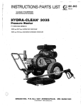
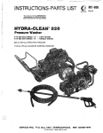
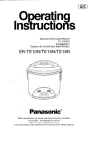
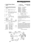
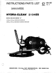
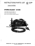
_- _
i1
QRllCO
.~.
t.
, .
,,
This manual contains IMPORTANT
WARNINGS and lMSTAUCTlQNS
READ AND RETAIN FOR REFERENCE
P/N 800-064 SERIES A
1500 psi(103 bar) OPERATING PRESSURE
1800 psi (124 bar) MAXIMUM WORKINGPRESSURE
Rev D
bR]$ECTIoN HAZARD
IF1 W E ,
~~~~~~~~~~~~~~~~~~~~~~~~~
~
~
~
~
,
~
~
Fluids under high pressure from spray or leaks can
penetratetheskinandcauseextremelyserious
injury, including the need for amputation.
Do not spray flammable liquids. Do not operate the
engine where combustible fumes or dust may
be
present.
NEVER point the spray gun at anyone or any part of
the body.
GAS
NEVER try to stop or deflect leaks with your hand or
body.
ALWAYS have the tip guardin place when spraying.
~
~
~
~~~~~~~~~~~~~~~~~~
~
F
\
m
W
E
~
A
~
K
S
O
E
Ifany
fluid appears topenetrateyourskin,
get
EMERGENCY MEDICAL CARE AT ONCE.
DO NOT TREAT &S A SIMPLE GUT.
Tell the doctor exactly what fluid was iniected. For
treatmentinstruction'shaveyourdoctorcallthe
NATIONAL POISON CENTER NETWORK
~
NEVER operate engine in a closedbuilding unlessthe
exhaustispipedoutside.Theexhaustcontains
carbon monoxide, a poisonous, odorlessand invisible
gas, which, if breathed, may cause serious illness
or
~
possibly
death.
NEVER make adjustments on machinery while it is
connected to the engine; first remove the ignition
cable
from
the
spark plug.
Turning
over
the
machinery by handduringadjusting
or cleaning
mightstarttheengineandmachinery.causing
serious injury to the operator.
(492I6B'I
-6669
AVOID COMPONENT RUQBWWE
NEVER run the engine with governor disconnected.
or operats at speeds in excess of 3600 RPM load.
~~~~~~~
Even after you shut off the gasoline engine, there is
high pressure in the pump, hose and gun until you
release it by triggering the gun.So before removing
the spray tip or servicing the unit, always shut offthe
unit andtrigger the gun to release pressure.
Precaution is thebest insurance against anaccident.
When starting the engine, maintain a safe distance
from moving parts of the equipment.
all accessory items
and
system
Be sure
that
components will withstand the pressure developed.
NEVER exceed the pressure rating of any component
in system..NEVER alter or modify equipment -your
as well as thefunction
of the
personalsafety,
equipment, isatstake. Maximum working pressure
1800 PSI (124 bar).
NEVER run the unit with the belt guard
removed.
Keep clear of moving partswhen the unitis running.
g: R]E A h p""v@%7"":
~
~
"
~
~
Before eachuse, check hose for weak, worn or damaged
conditions caused by traffic, sharp corners, pinching or
kinking.Tighten all fluid connections securely before
each use. Replace any damaged hose.
Observe
detergen't
manufacturer's
safety
precautions. Avoid getting detergentor other liquids
in your eyes. Follow the directions on the container
regarding
contact
with
eyes. nose, and skin,
breathing fumes, etc. Always wear full goggles to
protect youreyes from thespray as wejl as any debris
dislodged by the spray. If necessary. wear gloves or
other protective clothing. If antidotes or treatment
are recommended, be prepared to use them.
Do not use chemicalsor agentswhichare not compatible
with Buna-N and PVC or neoprene cover of hose.
D O N 1 spray toxic chemicals such as insecticide
weed killer.
or
Do not leave a pressurized
unit unattended. Shutoff the
unit and release Dressure before IeavinQ.
-
IMPORTANT
United States Government safety standards have been adopted under the Occupational Safety
and Health Act.
These standards - particularly the General Standards, Part
1910. and the Construction Standards, Part
1926should be consulted in connection with your use of airless spray equipment.
2
801-641
~
..
.~
. .
..
.
. .
. ...
~
~
~
NEVER fill fuel tank while engine is runningor hot.
Avoid the possibility of spilled fuel causing a fire.
Always refuel slowly to avoid spillage.
NEVER put hand or fingers over the spray tip,
MEDICAL ~
~
~
~
$
..
ENGINE KILL LEVER
7
P,
\
Refer to the engine instruction booklet provided with
the unit.
LSPRAY
HOSE
Connect To Water Supply
CAUTION
Install Hose and Spray Gun
Connect the spray hose to thespray gun by inserting
thepin
at theendofthehoseintothequick
disconnect coupler on the gun. Connect the hose t o
the fluid outlet in the same way.
Cleaning Accessories
For spraying detergentor other cleaning solution, we
a chemical
injector
kit.
See
recommend
using
Accessoriesandinstructionmanual801-645for
installation and operation.
Before attaching to water
supply. check local
plumbing code regarding cross-connection to
water supply.
Do not exceed 1 60°F (70%) water temperature to
pump in a direct supply system.
Connect a hose with at least a 3/4 in. (19 mm) ID
from yourcity water supply to the unit's
3/4 in.
garden hose threaded inlet. The supply hose should
not be more than 5 0 ft. (15 m)long.
NOTE:
For adirectsupply
system. yourwafer
source at the unit must have aflow rate of
AT LEAST 5 GPM (19 LITER/MINJ.
For removing rust and old paint we recommend using
a water sandblaster. See Accessoriesand instruction
If your operating conditions are different from
above.
manual 801-646 for installation and operation.
contact
our
Customer
Service
Department
for
assistance.
801-641
3
Startup
Before startino.
- and
-. be sure t o read the safety warninas
setup instructions.
~~
When shutting down for the day or weekend, shut off
unit, shut off water supply
valve, andtriggergun to
release pressure. Wipe off the unit with a damp rag.
Check the oil and gasoline levels daily.
CAUTION
Shut off cleaning unit whennot actually spraying.
for longer pump life.The pump will overheat if left
running for over 10 minutes without spraying.
Turn on the water supply
Trigger the gun to release any back pressure
DO NOT wire or tie
the gun
trigger intotheopen or
Set the choke and open the fuel valve.
NOTE:
Foreasier starting, hold the gun trigger open
while pulling the rope.
Put your foot on the frame or wheel to steady the unit
when you pullthe starter rope. Hold the gun inyour left
hand with the trigger open while starting the engine.
Grasp the starter rope grip and rapidly pull out the cord
two or three feet (1 m). Repeat if necessary with the
chokeopened slightly. Whentheengine
starts, immediately release the guntrigger.
Open thechoke
gradually.
CAUTION
Never run the cleaning unit dry. Costlydamage to
the pumpwill result. Alwaysbesurewatersupply
is completely turned on before operating.
Inspect all connections
for
necessary.
any
leaks.
Tighten
if
Cleaning
For Hydra-Clean technique. see the Chemical Injector
manual, 801 -645.
For abrasivecleaning,
manual, 801-646.
see theWaterSandblaster
Keep the nozzleand thetubepointedaway
from you and everyone else.
3. Do not put your hand over the tip to push the
nozzle into place. Grasp it from the side and
keep your fingers away from the tip.
4.
Do not let anyone else touch the sprayvalve
while you are cleaning nozzles.
5. Be sure the slip ring is pushed forward to lock
the nozzle in place before triggering the spray
~~~
~~
~~~
~
Shutdown and Care Of Unit
When unit is not in use, turn off water supply
4
.
801-641
. .-. .. .
,
DO NOT try to adjust the unloader valve or change the
engine speed. Changing these senings
may cause excessive pressure, interminent unloader operation, wastedfuel
and increased wear on parts and will void the warranry.
PUMP MUST NOT BE RUN DRY and must be drained
of water prior to exposure to freezing temperatures.Use
andstorethe
unit where it willnotbesubjectedto
freezing temperatures. If water does freeze in the unit,
thaw before trying to start. A 50% anti-freeze solution
may be pumped prior to cold weather storage.
Use only spray tips that are matched to the unit to avoid
excessive cycling and wear of the unloader valve. See
ACCESSORIES.
IC
Let a frozen plump thaw in a warm place. Don't
pour hot water on a frozenpump.Asudden
temperature
change
may
crack
the
ceramic
plungers.
-
~~
~~
~~
~
Do not pump caustic materials.
Before extended storage, flush the pump with light oil.
Avoid dragging hose over an abrasive surface such as
cement. This causes excessive wear
and shorter hose
life.
Clean the intake line strainer daily.
1. Shut off the cleaning unit and trigger the gun
to relieve pressure. Engage the trigger safety.
2.
Check the filter screen in the water inlet connection as
often as necessary. at least daily. Do not operate the
unit with the inlet and filter screen removed.
Lubrication and Care
Change the engine oil after every 100 hoursof operation. Drain oil with e'ngine warm. Engine requires 3
pints (1.4 liters) 30W oil. See separate instruction
manual for maintenance procedures.
Fill pump crankcase to dot on oil gauge window with
16 02. (0.47 liters) of crankcase oil (partno. 801-14441or
equivalent SAE 40 weighthydraulicoil with antiwear
and rust inhibitor additives.
Change initial fill after 50
hour running period. Change oil &ery 3 months or a t
XI0 hour intervals.
NEVER alter
valve.
i
Altering or adjusting unloader w;ll not increase
performance of unit.
Service of the unloader must be performed onlyby
qualified service personnel.
.i
'ROBLEM
CAUSE
SOLUTION
ingine Will Not Start
)r Hard To Start.
No gasoline in fuel tank or
carburetor.
Fill the tank with gasoline, open fuel shut-off
valve.
Check fuel line and carburetor.
Drain fuel tank and carburetor. Use new fuel
and dry spark plug.
Open choke and crank engine several times
to
clear out the gas.
Remove and clean.
Clean, adjust the gap or replace.
Water in gasoline or old fuel.
Choked improperly. Flooded
engine.
Dirty carburetor air filter.
Spark plug dirty or improper
gap.
Spray gun closed.
Engine Misses Or Lacks
'ower
.ow Pressure
Trigger spray gun.
Partially plugged air filter.
Spark plug dirty, wrong gap,
or wrong type.
Incorrect ignition timing.
Remove and clean.
Clean, adjust the gap, or replace.
Worn nozzle.
Belt slippage.
Replace with nozzle of proper size.
Tighten or replace; use correct beltsand replace
both at same time.
Disassemble, reseal, and reassemble.
Clean, and adjust relief valve; check for worn
and dirty valve seats. Kit available.
Time engine.
Air leak in inlet DlUmbing
.
Relief valve stuck, partially
plugged or improperly
adjusted; valve seat worn.
Inlet suction strainer clogged01 Clean. Use adequate size. Check more
improper size.
frequently.
Worn packing. Abrasives in
Install proper filter. Check flow available to
pumped fluid or severe cavita- pump.
tion. Inadequate water supply.
Fouled or dirty inlet or dischargf
Clean inlet and discharge valve assemblies.
valves.
Worn inlet or discharge valves. Replace worn valves, valve seats and/or
Leakv discharge hose
discharge hose.
'ump runs extremely rough Restricted inlet or air entering
the inlet plumbing.
)ressure low.
Inlet restrictions and/or air
leaks. Stuck inlet or discharge
valve.
Leaking H.P. seals.
Pro er size inlet plumbing; check for air tight
sear
Clean out foreign material,replace worn valves.
Nater kaka e from under
he manifolcf!
Worn packing.
Install new packing.
Nater in pump crankcase.
May be caused by humid air
condensing into water Inside
the
crankcase.
Change oil at 3 month or 5CO Hour intervals using
Crankcase Oil (other ap roved oilevery month or
200 hours) P.N. 801-r44.
'requent orprematurefailurl
Scored plungers.
Over pressure to inlet manifold
Damaged or worn plungers.
Abrasive material in the fluid
being pumped.
Excessive pressure and./or
temperature of fluld bemg
pumped.
Over pressure of pumps.
Running pump dry.
Replace plungers.
Reduce inlet pressure.
Replace plungers.
Install proper filtration on pump inletplumbing.
)f the packmg.
. .
.,-
ReDlace seals.
Check pressures andfluid inlet temperature;be
jure they are within specifled range.
?educe pressure.
30 not run pump without water.
'
strong surging at the inlet
nnd low pressure on the
lischarge side.
Foreign particles in the inlet or
discharge valve, or worn inlet
and/or discharge valves.
:heck for smooth lap surfaces on inlet and
$ischar e valve seats. Discharge valve seats and
nlet vabeseats mavbe lapped on a
veryfineoll
;tone
801-641
.. .
.
..
..
.
.
.~~
...
".
.
.
...
. .
5
.
6
..
..
801-641
.
. ..
.. .,,"..
_.
.
..,,
~~.. . .
., .. . . .
.
.
~
.
~
..
.
.
~.
.
I
Pressure
Washer
Assembly,
800-064
~
!
REF. PART
NO. No.
1
800-130
5 '801-665
'801.666
2
4
5
800-081
801-230
6
801-129
801-141
7
8 801-542
9 801-131
10 801-594
11 801-087
12 801-942
13 801.022
14 801-941
15 801-531
16 801-546
17 801.872
18 801-023
19 801-015
20 801-139
21 801-025
22 801-363
23 801-024
24 801-499
25 801-020
26 801-701
27 801-548
28 801-007
29 801-591
30 801-934
31 801-137
32 *801-069
DESCRIPTION
CITY.
GUN ASSEMBLY, see parts
1
drawing/list page 10
TIP. 0006 MEG, 1/4 thd.. Oo
1
TIP, 1506 MEG, 1/4 thd.. 15O
1
PUMP ASSEMBLY. see Darts
drawing/list page 9
1
BELT, drive
1
LABEL, warning
1
DECAL, caution
1
LABEL identification
1
PLATE. serial no.
1
ENGINE. 7 h.0.
1
SCREW, 'md. kt., 1/+20 x 1 -3/4"
5
SCREW, hex hd., 5/16-18 x 3
1
4
SCREW, hexhd..5/16-18~1-3/4
SCREW, hex hd.. 5/16-18 x 1"
4
SCREW. hex hd., 31818 x 7"
1
4
SCREW, hex hd.. 3/6-16 x 1-1/4"
4
SCREW, hex hd.. M6 x 20 MM
WASHER, flat. 1/4
24
WASHER, flat. 5/16
5
WASHER, lock, 1/4
4
WASHER, lock, 5/16
12
WASHER, lock, 3/8
4
NUT, 5/16-18
11
NUT. lockino. 3/8-16
1
NUT; locking; 1/2-13
2
SCREW, hex hd., 1/4-20 NC x 1/2
2
GROMMET
5
HOSE, H.P.. 1/4 x 50 ft.
1
PULLEY, pump
1
PULLEY, enaine
1
KEY, pulley
1
QUICKCOUPLE, female
2
REF. PART
NO.
NO.
33 '801-090
34 '801 -552
35 801-723
36 800-080
37 801-529
38 801-177
39 801-541
40 801-539
41 801-537
42 801-505
43 801-506
44 801-573
45 801.504
46 801-132
47 801-593
48 801-550
49 "801-553
50 801-130
51 801.605
52 801-606
53 801-612
54 801-875
55 801-367
56 801-608
57 801.609
58 801-555
59 801-103
60 801-521
61 801.520
DESCRIPTION
OUICKCOUPLE. male
TIP. 2506 M E G I 1/4 thd.. 2Fo
LABEL. Model 1535
CHASSIS WELDMENT
BELTGUARD. base
BELTGUARD, cover
HANDLE
BUMPER
WELDMENT, leg support
FOOT RETAINER
BOOT. lea"
AXLE
FOOT
RIVET. drive
SPRING
WHEEL
TIP. 4006 MEG. 1/4 thd.. 40°
LABEL, warning
SCREW. hex hd.. #lo-24 NC
WASHER, flat, 3/16
WASHER. flat. 7/16
WASHER; IO&, #IO
BUMPER
PIN, roll
8RACKET. suppon
QTY.
5
1
1
1
1
1
1
1
1
1
1
1
1
2
1
2
1
1
1
1
2
1
1
1
1
iL chk. oil
RAIL STIFFNER
1
1
1
1
BRACKET
Order p a r k b y name and series letter of the assembly for
which you are ordering.
'Recommended "tool bow" spare parts.
PARTS DRAWING
Unloader Assembly,
1500 PSI (103 bar) Max.
PARTS LIST
Unloader Assembly, 800-132'
REF. PART
DESCRIPTION
NO. NO.
1 801-045
2 801-046
3 801-047
4 801-048
801-049
5
6 801-050
800-123
7
8 801-059
9 801-412
10 801-432
801-062
11
12 801-063
13 801-068
14 801-069
15 801-070
801-071
16
17 801-939
QTY.
1
1
1
1
1
2
1
CAGE, valve
O-RING
SPRING
BALL
SEAT
O-RING
UNLOADER
SUB-ASSEMBLY
O-RING
HOUSING
. ~
~-.
CYLINDER
O-RING
PLUG
HOUSING VALVE
SPRING
VALVE
SEAT
O-RING
1
1
1
1
1
Order parts by name and series letter of the assembly for
which you are ordering.
801-641
...
.
..
. ~.
. ~ . ,,,.
. . . . . .
.
,.
. ..
..
7
NOTE:
Three
sizes
of metric
wrenches
are
necessary forservicingthe
pump; M30,
M10 and M 6 Allen wrench.
Valves:
1 . Remove the hex plug (5)from manifold
(6)using M30
wrench.
8. Lubricate each plunger and carefully slide manifold
onto crankcase.
9. Replace the eight capscrews and snug them
Torque to 16 ft. Ibs. (2.2 K/m).
NOTE: The eightcapscrewsmustbetorqued
evenly to apply equal pressure onthe
manifold so that it seatsproperly
and
doesn't bind or jam. This is best done by
torquing bolts closest to the center of the
manifold first and then working out from
those bolts.
2. Examine O-ring (4) under plug and replace if cutsor
distortion exist.
3. Remove valve unit and O-ring (3)from cavity.
NOTE: Valve unit may comeapartduring removal.
4. Replace valve unit with P/N 801 -472.
up.
Servicing V-Packings:
NOTE: Use packing repair kit PIN 801-662.
5. Replace hex plugand torque to75ft. Ibs. (10.3K/m).
NOTE: Hex plug should be re-torquedafter5
hours operation.
1. Afterremovingtheeightcapscrewsandthe
manifold carefully pull packing retainer (14) from
the manifold. Examine O-ring (15) and replace if
necessary.
Pumping Section:
1. Remove the eight Allen head cap screws (1) from
the manifold using the M6 Allen wrench.
2. Remove low pressure packing (12) and head ring
2. Carefully separatethe manifold from the
crankcase.
3. Pull intermediate retainer ring(l3)from manifold,
(11).
high pressure packing (12) and head ring (1 ).1
NOTE: It may be necessary to tap manifold lightly
with mallet to loosen.
4. Inspect all parts and replace if necessary.
r 1
NOTE: If just the packings are'needed use kit
with ceramic
Keep manifoldproperlyaligned
plungerswhenremovingto
avoiddamage to
plungers or seals.
801-662. rings
If or
retainers
need
replacement use kit 801-664.
5. Thoroughly clean packing cavity in manifold and
examine. Lightly grease packing cavity.
3. Carefullyexamineeachplunger(21)forany
scoring and replace if necessary.
Servicing Plungers:
1. Loosen plunger retaining screw (17) 5-6 turns,
using "10
wrench. Push
plunger
towards
crankcase.
This
will separate
plunger
and
retaining screw.
2. Remove retaining
screw
from
plunger
and
examine O-ring (19).back-up ring(ZO), and copper
bearing/gasket washer (18). Replace if necessary
using plunger repair kit P/N 801-663.
3; Remove plunger from plunger rod and remove
copper flinger (22). Clean or replaceif necessary.
4. Lightly grease flinger and replaceit on plunger rod.
5. Replace plunger.
6. Lightly grease retaining screw assembly to avoid
cutting O-ring. Lightly grease outer end of plunger.
6. Replace packing assembly in the following order:
headring(ll),packing(12),intermediatering(l3),
head ring (11). packing (12), packing retainer(l41
and O-ring (15).
CAUTION
Carefully study the location of each part andthe
position of the seals to assure proper reassembly
and operation.
7. Lubricate each plunger and carefully slide manifold
onto crankcase.
NOTE: When
replacing
.the manifold
onto
plungers,
extreme
caution
should
be
exercised to avoid damage to the seals.
8. Replace the eight capscrews in the manifold and
tighten as previously
described
(step
9 under
servicing plungers).
7. Install retaining screw assembly into plunger and
torque to 14.4 ft. Ibs. (2 K/m).
.
... .
,
., :
. . . ..
'... . .
8
.
..
801-641
. .
~
..
. . . . -. .. .
..
i
TIl)
Includes:
L11'-12-14
13
PLUNGER
REPAIR
KIT 801 -474
.,
'I(
Includes:
VALVEUNITOILSEALKIT
KIT 801 -472 801 -658
Includes:
Includes:
Includes:
REF.
REF.
NO.
16
QTY
6
NO.
3
NO.
1
2
3
4
5
6
7
8
9
10
11
12
13
14
15
16
17
18
19
20
21
.
"
NO.
801-651
801-652
801-852
801-470
801-471
801-650
801-485
801-484
801-482
801-483
801-655
801-653
801-654
801-656
801-657
801-778
801-493
801-492
801.488
801-491
801-661
"PACKING 81 RETAINER
KIT 801-664
~ 1 5 ~ 1 6
PACKING KIT
801-662
REF.
QTY
3
NO.
12
QTY
6
REF.
NO.
17'
18
19
20
QTY
3
3
3
3
REF.
NO.
11
12
13
14
15
QTY
1
1
1
1
1
*Three kits needed
for entire pump.
REF. PART
DESCRIPTION
SCREW. M8 x 60 MM
WASHER, 8.4 x 13 x 0.8 MM
VALVE UNIT
O-RING
HEX PLUG, M24 x 2 x 16 MM
MANIFOLD
WASHER
CAP, 3/8 NPT
CAP, 1/2 NPT
WASHER
HEAD RING
PACKING
INTERMEDIATE RING
PACKING RETAINER
O-RING
OIL SEAL
PLUNGER RETAINING SCREW
WASHER
O-RING
BACK-UP RING
PLUNGER
QTY
8
8
6
6
6
1
1
1
1
1
6
6
3
3
3
3
3
3
3
3
3
NO. NO.
22 801-660
23 801-659
801.108
24
25 801-913
26 801.105
27 801-106
28 801-110
29
801-11
1
30 801-112
801.597
31
800.132
32
DESCRIPTION
QTY
FLINGER
3
OIL DiPSTlCK
1
HEX REDUCER
1
REDUCER BUSHING
1
NIPPLE, 1/2 NPT x 3-1/2"
1
TEE, 1 /2 NPT
1
HOSE ADAPTER.
1
HOSE CONN. NUT
1
INLET SCREEN
1
HOSE, low pressure
1
UNLOADER ASSEMBLY. see
parts drawing/list. page 7
1
33 801 -090
QUICK COUPLE, male
1
34 801-575
TENSIONER, belt
2
801-560
35
PUMP
1
801.910
36
1
PLUG, Dlastic
37 801-907 aluminum
WASHER,
1
TAG, caution
38 801-143
1
39 801-524
1
LABEL, pump
Order parrs by name and series letter of the assembly for
which you are ordering.
801-641
9
PART$
Gun Assembly, 800-130
REF.PART
NO. NO.
1 801-134
SERVICE
Gun, Cartridge Replacement
I"liri"W
..eA8,8!*
1. Press accesspin (12)from gun handle and remove
access plate (14) byslidingplatebackwards.
Remove cartridge (5)from housing (6) by using a
19 m m socket wrench.
2. Check inside housing to be sure all O-rings came
out when cartridge was removed. If O-ring can be
seen inside the housing, remove it, being careful
not to damage internal threads in housing.
3. Throw away old cartridgeand install newcartridge
using a small amount of pipe sealant on threads.
Be sure totighten cartridgefirmlyagainst housing.
2
3
4
801-674
801-009
801-638
5 801-639
6 801-671
7 801-670
8 801-256
9 801-424
801-672
10
11 801-673
12 801-428
13 801-419
801-427
14
15 801-420
801-423
16
17 '801 -202
DESCRIPTION
QTY
TUBE. 32"
1
GRIP
1
COUPLER, female quick disconnect
1
SPRAY GUN, lreDlaceable
1
pans include items 5-18)
CARTRIDGE
1
HOUSING
1
HEX PLUG
1
. TRIGGER PIN
1
. TRIGGER
1
. OUTLET
1
. PIN COVER
2
. ACCESS PIN
1
HANDLE
1
. ACCESS P M T E
1
. TUBE
1
. INLET FllTlNG
1
O-RING. quick couple
1
Order parrs by name and series letterof the assembly for
which you are ordering.
4. Slide access plate into place and install access pin. *Recommended "tool box" spare parts.
.
ENGINE BRIGGS & STRATTON
4 cycle, single cylinder
air cooled, 7 hp
GASOLINE TANK 4 quarts (3.79 liter)
capacity
!
WATERPUMP:
1500 PSI (103 bar) mar.
pressure; 3-1/2 GPM
(13.25 liter/min).
WEITED PARTS: StainlessSteel.Aluminum.
Phenolic Plastic. Ceramic
Liners, Nitrile Rubber.
UNITWEIGHT:
156 Ib I71 kg1
OVERALL DIMENSION: Length: 4 0 (1016 mm)
Widlh: 28" (711 mm)
Height: 24" (610 mm)
MAX. WATERTEMPERATURE:
INLETHOSECONNECTION:
160° (70" CI
3 / 4 garden hose (I)
..
THE GRACO WARRANTY
Gracolnc.warrantsallequipmentmanufacturedbyitandbear~ngitsnametobefreefromdefectsin
material and workmanshlp under
normal use and Seivtce. This warranty extends to the ortglnal
purchaSerforaperiodaf12monthsframthedateofpurchaseandappliesonlywhentheequipment
is installed and operated !n accordance with written factory recommendationsThis warrantydoes
of Graco, awes from misuse.
not cover damage or wear which. in the reasonable judgment
abrasion. corrosmn. negligence. accident, SubstltUtion of "on-Gram parts. faulty installation or
tampering.
Thts warranty is conditmned upon the prepad returnof the equipment clalmed to be defectwe for
examlnallon by Graco to verify the claimed defect. If the claimed defect
verified.
is Graco will repam
or replace free of charge. any defective parts.
The equipment will be returned to the origlnal
purchaser transportation prepald. If mspection of the equpment does not disclose any defect in
warkmanshipor material, repam will bemadeatareasonablechargeandreturntransportation will
be charged.
THIS LIMITED WARRANTYIS EXCLUSIVE.AND IS IN LIEU OF ANY OTHER WAdRANTlESlEXPRESS
OR IMPLIED) INCLUDINGWARRANTY OF MERCHANTABILITY OR WARRANTY OF FITNESS FOR A
PARTICULAR PURPOSE AND OF ANY NON-CONTRACTUAL LIABILITIES INCLUDING PRODUCT
LIABILITIESBASED O N NEGLIGENCE OR STRICT LIABILITY. EVERY FORM OF L l A B l L l N FOR
DIRECT, SPECIAL OR CONSEQUENTIAL DAMAGES OR LOSS IS EXPRESSLY EXCLUDED AND
DENIED.
EOUIPMENT NOT COVERED BY GRACO WARRANTY. Accessor~esoc components of equcpment
sold by G r a m that are not manufactured by Graco (such as electric motors, SwtCheS, hose, etc.)are
subject tothe warranty. ifany. of their manufacturer.Graco will provide purchaserwlfh reasonable
ass~stance~n making such claims.
Factory Branches: Atlanta. Dallas, Detroit. Los Angeles, West Caldwell (N.J.1
Subsidiary end Affiliate Companies: Canada: England: Switzerland: France; Germany: Hang Kongi Japsn
GRACO IMC.
-.
.
..
-
. ..
~
.. .
P.Q. BOX 844'1
MINMEAPQLBS, MN 55440-1444
PRINTED
U.S.A. IN
. ~ . ... .
REV
801-641
45-10058
4/85
..
.... .
..
.....,..
~,~
D