1
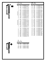
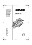
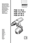
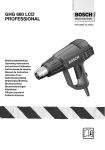
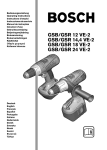
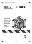
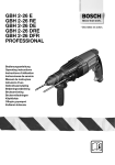
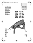
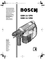
GBH 24 VFR-VRE - Vorderseite Seite 1 Mittwoch, 28. August 2002 2:38 14
Bedienungsanleitung
Operating Instructions
Instructions d’emploi
Instrucciones de servicio
Manual de instruções
Istruzioni d’uso
Gebruiksaanwijzing
Betjeningsvejledning
Bruksanvisning
Brukerveiledningen
Käyttöohje
Oδηγία χειρισµού
Kullanım kılavuzu
Deutsch
English
Français
Español
Português
Italiano
Nederlands
Dansk
Svenska
Norsk
Suomi
Eλληνικά
Türkçe
GBH 24 VFR
GBH 24 VRE
Ø
L
(mm) (mm)
Ø
L
(mm) (mm)
ø
3,5
4
4
5
5
5
5,5
5,5
5,5
5,5
6
6
6
6
6,5
6,5
6,5
6,5
6,5
7
7
7
8
8
8
8
8
8
9
9
L
50
50
100
50
100
150
50
100
150
200
50
100
150
200
50
100
150
200
250
50
100
150
50
100
150
200
400
550
100
150
2 608 597 773
1 618 596 231
2 608 597 774
1 618 596 164
1 618 596 189
2 608 596 199
1 618 596 165
2 608 596 146
2 608 597 775
2 608 597 776
1 618 596 166
1 618 596 167
2 608 596 115
2 608 597 777
1 618 596 168
1 618 596 169
2 608 597 778
2 608 597 779
2 608 597 780
1 618 596 170
1 618 596 171
2 608 597 130
1 618 596 172
1 618 596 173
1 618 596 174
1 618 596 264
2 608 596 116
2 608 596 183
2 608 596 158
1 618 596 175
Ø
L
(mm) (mm)
ø
L
2 • 1 619 929 589 • 02.08
16
18
18
20
20
400
200
400
200
400
2 608 597 000
2 608 597 001
2 608 597 002
2 608 597 003
2 608 597 004
10
10
10
10
10
10
10
10
11
11
11
11
12
12
12
12
12
13
13
13
14
14
14
14
14
15
15
16
16
50
100
150
200
250
300
400
550
100
150
200
250
100
150
200
250
400
100
150
200
100
150
200
250
400
100
200
150
250
1 618 596 176
1 618 596 177
1 618 596 265
1 618 596 178
1 618 596 315
1 618 596 266
1 618 596 267
2 608 596 117
1 618 596 179
1 618 596 316
1 618 596 180
2 608 597 781
1 618 596 181
1 618 596 268
1 618 596 182
2 608 597 782
1 618 596 269
1 618 596 183
1 618 596 318
1 618 596 184
1 618 596 185
1 618 596 270
1 618 596 186
1 618 596 271
2 608 596 118
1 618 596 187
1 618 596 188
1 618 596 185
1 618 596 186
Ø
L
(mm) (mm)
Ø
L
(mm) (mm)
ø
L
10
12
12
14
14
15
16
16
16
16
17
18
18
950
550
950
550
950
400
400
550
750
950
150
150
250
2 608 597 122
1 618 596 224
2 608 597 123
1 618 596 225
2 608 597 124
1 618 596 257
1 618 596 259
1 618 596 226
1 618 596 227
2 608 597 125
1 618 596 203
1 618 596 204
1 618 596 319
2 602 025 120
b
18
18
18
18
19
19
19
20
20
20
20
20
400
550
750
950
150
250
400
150
250
400
550
950
1 618 596 260
2 608 596 120
2 608 596 122
2 608 597 126
1 618 596 205
1 618 596 320
1 618 596 261
1 618 596 207
1 618 596 262
1 618 596 263
1 618 596 321
2 608 597 127
a = Ø 16 mm
b = 250 mm
1 618 600 009
a = 22 mm
b = 250 mm
1 618 600 010
2 603 001 010
a
2 607 018 296
1 605 439 002
1 617 000 132
1 608 571 062
(Ø 1,5 – 13 mm)
2 607 000 206
3 • 1 619 929 589 • 02.08
24 V/1,7 Ah (NiCd)
2 607 335 082
24 V/3,0 Ah (NiCd)
2 607 335 216
AL 60 DV 2425
2 607 224 426 (EU)
2 607 224 428 (UK)
2 607 224 430 (AUS)
AL 15 FC 2498
2 607 224 484 (EU)
2 607 224 486 (UK)
2 607 224 488 (AUS)
5
4
3
6
7
2
1
12
8
9
11
10
A
B
13
4 • 1 619 929 589 • 02.08
GBH 24 VFR
14
C
D
2
E
ZU
AUF
15
GBH 24 VFR
17
F
X
12
4
5 • 1 619 929 589 • 02.08
G
16
Tool Specifications
Rotary Hammer
Order number
Rated power
Output power
Rated speed
Impact rate
Impact energy per stroke
Tool holder
Drilling output:
- Concrete (twist drill bit)
- Wood
- Steel
Weight with battery,
approx.
Battery
Order number
Temperature control
Rated voltage
Capacity
Weight, approx.
GBH 24 VFR
0 611 261 7..
350
270
0 – 1 000
0 – 4 400
1.3
SDS-plus
GBH 24 VFR
0 611 261 5..
350
270
0 – 1 000
0 – 4 400
1.3
SDS-plus
GBH 24 VRE
0 611 260 7..
350
270
0 – 1 000
0 – 4 400
1.3
SDS-plus
GBH 24 VRE
0 611 260 5..
350
270
0 – 1 000
0 – 4 400
1.3
SDS-plus
[mm]
[mm]
[mm]
4 – 20
max. 20
max. 10
4 – 20
max. 20
max. 10
4 – 20
max. 20
max. 10
4 – 20
max. 20
max. 10
[kg]
3.5
NiCd
2 607 335 082
NTC
24
1.7
1.3
4.2
NiCd
2 607 335 216
NTC
24
3.0
2.0
3.5
NiCd
2 607 335 082
NTC
24
1.7
1.3
4.2
NiCd
2 607 335 216
NTC
24
3.0
2.0
[W]
[W]
[rpm]
[bpm]
[J]
[V]
[Ah]
[kg]
Please observe the order number of your machine. The trade names of the individual machines may vary.
Machine Elements
1
2
3
4
5
6
7
8
9
10
11
12
13
14
15
16
Noise/Vibration Information
Dust protection cap
Locking sleeve
Chuck locking ring
Push-button for depth-stop adjustment
Impact stop switch
Rotational direction switch
On/Off switch
Button
Battery charge display
Battery
Auxiliary handle
Depth stop
Release button
Protective cap
Interlock
Knurled ring
Measured values determined according to
EN 50 144.
Typically the A-weighted noise levels of the product are: sound pressure level: 91 dB (A); sound
power level: 104 dB (A).
Wear hearing protection!
The typically weighted acceleration is 11 m/s2.
Intended Use
The machine is intended for hammer drilling in
concrete, brick and stone. It is also suitable for
drilling without impact in wood, metal, ceramic
and plastic. Machines with electronic control and
right/left rotation are also suitable for screwdriving and thread cutting.
Not all of the accessories illustrated or described are
included as standard delivery.
13 • 1 619 929 589 • TMS • 08.08.02
English - 1
For Your Safety
■
■
■
■
■
■
■
■
■
■
■
Working safely with this machine is possible only when the
operating and safety information
are read completely and the instructions contained therein are
strictly followed. In addition, the
general safety notes in the enclosed booklet must be observed. Before using for the first
time, ask for a practical demonstration.
Wear protective glasses and hearing protection.
For long hair, wear hair protection. Work only
with closely fitting clothes.
Before each use, check the machine and battery. If damage is detected, do not use the machine. Have repairs performed only by a qualified technician. Never open the machine yourself.
Use power tools only with specifically designated battery packs. Use of any other battery packs may create a risk of injury and fire.
Under abusive conditions, liquid may be
ejected from the battery; avoid contact. If
contact accidentally occurs, flush with water. If liquid contacts eyes, additionally
seek medical help. Liquid ejected from the
battery may cause irritation or burns.
Before any work on the machine itself (e. g.
maintenance, tool change, etc.) as well as
when transporting and storing, always set
the rotational direction switch to the centre
position. Otherwise danger of injury is given
when unintentionally actuating the On /Off
switch.
Ensure the switch is in the off position before inserting battery pack. Inserting the battery pack into power tools that have the switch
on invites accidents.
Convince yourself before using that the battery
is securely seated in the machine.
Do not strain the machine so heavily that it
comes to a standstill.
When working with the machine, always hold it
firmly with both hands and provide for a secure
stance.
Use the machine only with the auxiliary handle 11.
14 • 1 619 929 589 • TMS • 08.08.02
■ Hold the power tool only by the insulated
gripping surfaces, when performing an operation where the cutting tool may run into
hidden wiring.
Contact with a “live” wire will make exposed
metal parts of the tool “live” and shock the operator.
■ Use appropriate detectors to determine if
utility lines are hidden in the work area or
call the local utility company for assistance.
Contact with electric lines can lead to fire and
electric shock. Damaging a gas line can lead
to explosion. Penetrating a water line causes
property damage.
■ Be careful when screwing in long screws; danger of sliding off.
■ Set the machine against the screw /nut only
when switched off.
■ When screwdriving, operate in first gear as
well as with a low speed.
■ Always switch the machine off and wait until it
has come to a standstill before placing it down.
■ Never allow children to use the machine.
■ Bosch is only able to ensure perfect operation
of the machine if the original accessories intended for it are used.
Battery and Battery Charger
■ The enclosed operating instructions for the
battery charger must be read carefully!
■ Recharge only with the charger specified
by the manufacturer. A charger that is suitable for one type of battery pack may create a
risk of fire when used with another battery
pack.
■ Allow a heated battery to cool before charging.
■ Protect the battery from heat and fire: Danger
of explosion! Do not place the battery on radiators or expose to strong sun rays for a longer
time; temperatures over 50 °C cause damage.
■ Do not open the battery, and protect it from impact. Store in a dry and frost-free place.
■ When battery pack is not in use, keep it
away from other metal objects like paper
clips, coins, keys, nails, screws, or other
small metal objects that can make a connection from one terminal to another.
Shorting the battery terminals together may
cause burns or a fire.
■ Do not dispose of the battery in household
waste or discard into fire or water.
English - 2
Before Putting into Operation
Auxiliary Handle/Depth Stop
(see figure F )
Battery Charging
A battery that is new or has not been used for a
longer period does not develop its full capacity
until after approximately 5 charging /discharging
cycles.
To remove the battery 10, push back the release
button 13 and pull the battery out downwards. Do
not exert any force (see figure A ).
Please refer to the enclosed “Battery Charger” instructions for the operation of the battery charger
as well as for a description of the charging process.
The battery is equipped with an NTC temperature
control which allows charging only within a temperature range of between 0 °C and 45 °C.
A long battery service life is achieved in this manner.
A significantly reduced working period after
charging indicates that the batteries are used and
must be replaced.
■ Observe the notes on environmental protection.
■ Use the machine only with the auxiliary
handle 11.
Loosen the handle by turning to the left. Rotate
the auxiliary handle 11 and adapt to the working
position. Make sure that the clamping band 17 of
the auxiliary handle remains in the groove.
Firmly retighten the handle.
The drilling depth can be set with the depth
stop 12.
For this, press the push-button for the depth-stop
adjustment 4, adjust the required drilling depth X
and release the push-button for the depth-stop
adjustment 4 again.
The ribbing on depth stop 12 must point upwards.
Battery Charge Display
☞
40 – 60 %
■ Before any work on the machine itself, remove the battery.
With the SDS-plus tool holder, simpler and easier
tool changing is possible without additional aids.
Grease the shank end of the tool regularly.
The dust protection cap 1 largely prevents the
entry of drilling dust during operation. When inserting the tool, take care that the dust protection
cap 1 is not damaged.
A damaged dust protection cap should be
changed immediately. We recommend having
this carried out by an after-sales service.
As a requirement of the system, the
SDS-plus tool must rotate freely. At no-load
speed, this leads to a certain amount of radial run-out.
This does not affect the accuracy of the drill
hole, as the bit is automatically centred during drilling.
60 – 80 %
Inserting (see figure
80 – 100 %
Clean and grease the shank end of the tool.
Insert the tool in a twisting manner into the tool
holder until it locks. Check if it has locked by pulling the tool.
The battery 10 is fitted with a battery charge display 9. It indicates the charge of the battery at
any given time during the working process.
By pressing the button 8, the battery charge can
also be checked when the battery has been removed, or when the machine is at a standstill. After approx. 4 seconds the battery charge display
automatically turns off.
Battery charge:
0 – 10 %
10 – 20 %
20 – 40 %
9
8
When the first display element begins to flash
(0 – 10 %) the battery is almost empty and must
be recharged.
To maintain the accuracy of the display, occasionally discharge the battery until the speed of
the machine is considerably reduced and the battery charge display has completely turned off.
Frequent recharging after short intervals of use
impairs the accuracy of the display.
15 • 1 619 929 589 • TMS • 08.08.02
Changing the Tool
☞
C
Removing (see figure
)
D
)
Push back the locking sleeve 2 of the tool holder
and remove the tool.
English - 3
Reversing the Rotational Direction
Initial Operation
Inserting the Battery
Before re-inserting the battery 10 remove the
protective cap 14 if necessary (see figure B ).
Set the rotational direction switch 6 to the centre
position (locked off). Slide the charged battery 10
into the handle until it can be felt to latch.
Switching On and Off
To start the machine, press the On/Off switch 7
and keep it depressed.
The machine runs with variable
speed between 0 and maximum,
depending on the pressure applied
to the On/Off switch 7. Light pressure on the On/Off switch 7 results
in low rotational speed, thus allowing drilling to begin in a smooth,
controlled manner. Further pressure on the switch results in an increase in speed.
To switch off the machine, release the On/Off
switch 7.
Do not strain the machine so heavily that it comes
to a standstill.
■ The machine is not suitable for stationary operation, e. g., in a drill stand.
Operate the rotational direction switch 6
only at a standstill.
The rotational direction switch 6 is used to reverse the rotational direction of the machine.
However, this is not possible with the On /Off
switch 7 actuated.
Right Rotation
Turn the rotational direction switch through to
the left stop (normal operation: drilling, screwdriving, etc.).
Left Rotation
Press the rotational direction switch through to
the right stop (for loosening and unscrewing
screws and nuts).
Impact Stop Switch
■ Set the impact stop switch 5 to “Drilling”
(only at a standstill).
Set the impact stop switch 5 to the desired position:
Drilling
Overload Clutch
If the drill bit jams or edges, the drive to the
drill spindle is interrupted.
Due to the arising forces always hold the machine firmly with both hands and provide for
a secure stance.
Before pulling out a stuck tool insert, first remove
the machine from it.
Hammer drilling
Electric Brake
When releasing the On/Off switch 7 the speed of
the drill chuck is reduced to a stop, thus preventing the run-on of the tool.
Any sparking occurring during this process in the
area of the upper ventilation slots is normal and
does not damage the machine.
For screwdriving applications, wait until the screw
is flush with the material and then release the
On/Off switch 7. The screw head does not penetrate into the material then.
16 • 1 619 929 589 • TMS • 08.08.02
English - 4
Open the Keyless Chuck
(see figure E )
Change the SDS-plus
Tool Holder (GBH 24 VFR)
The SDS-plus tool holder can easily be replaced
by the keyless chuck supplied with the machine.
The keyless chuck serves for rapid insertion of
the tools without the SDS-plus (e. g. round shaft
drill, screwdriver bits).
Do not hold the machine by the chuck!
Removal
■ Danger of injury! Before removing the
chuck, make sure to remove the tools or
bits.
Tightly grip the chuck locking ring 3 and pull
strongly in the direction of the arrow. Remove the
chuck.
3
Loosen chuck by turning the interlock 15 clockwise AUF .
Open chuck by turning it counter-clockwise.
Clamping the Tool
Insert the tool and manually close chuck while
holding knurled ring 16.
Lock chuck by turning interlock 15 counter-clockwise
ZU .
Set the impact stop switch 5 to “Drill”.
Removing the Keyless Chuck
Tightly grip the chuck locking ring 3 and pull it
strongly in the direction of the arrow.
Key Type Drill Chuck for Tool
Inserts with Cylindrical Shank
(GBH 24 VRE)
Tool inserts with cylindrical shank can be
clamped with the key type drill chuck (accessory)
and the corresponding adapter (accessory).
Set the impact stop switch 5 to “Drilling” (only at a standstill).
Clean and lightly grease the adapter shank.
Insert the assembled chuck with a twisting manner into the tool holder until it latches. The chuck
locks itself. Check the locking by pulling on the
chuck.
☞
Mounting
Using the whole hand, tightly grip the chuck.
Twist it onto the taper shaft of the chuck until it is
clearly heard to latch. The chuck automatically
locks.
Check the locking function by pulling at the
chuck.
Keyless Chuck for Tools with a
Cylindrical Shaft (GBH 24 VFR)
Tools with a cylindrical shaft can be clamped using the keyless chuck.
The keyless chuck is not suitable for
hammer drilling.
☞
Mounting the Keyless Chuck
Remove the SDS-plus tool holder. Mount the
keyless chuck in the same way as the SDS-plus
tool holder.
17 • 1 619 929 589 • TMS • 08.08.02
Screwdriving (see figure
G
)
The machine is also suitable for occasional
screwdriving applications, however, not for
screwdriving applications with extreme reductions of speed at which the overload
clutch frequently responds.
For screwdriving, the universal bit holder with
SDS-plus shank (accessory) must be used.
– Set the impact stop switch 5 to “Drill”.
– Set the direction of rotation to right-hand rotation.
– Regulate the speed with the On/Off switch 7.
English - 5
Maintenance and Cleaning
■ Before any work on the machine itself, remove the battery.
For safe and proper working, always keep
the machine and the ventilation slots clean.
■ Keep the tool holder clean at all times.
☞
Changing the Dust Protection Cap
A damaged dust protection cap should be
changed immediately. We recommend having
this carried out by an after-sales service.
If the machine should fail despite the care taken
in manufacturing and testing procedures, repair
should be carried out by an after-sales service
centre for Bosch power tools.
In all correspondence and spare parts orders,
please always include the 10-digit order number
given on the nameplate of the machine.
Environmental Protection
Recycle raw materials instead of
disposing as waste
The machine, accessories and
packaging should be sorted for environmental-friendly recycling.
These instructions are printed on recycled paper
manufactured without chlorine.
The plastic components are labelled for categorized recycling.
Nickel-cadmium-battery:
If your product is equipped
with a nickel-cadmium-battery, the battery must be
collected, recycled or disposed of in an environmentally-friendly way.
Defective or worn out batteries must be recycled
according to the guidelines 91/157/EEC.
Batteries no longer suitable for use can be
directly returned at:
Great Britain
Robert Bosch Ltd. (B.S.C.)
P.O. Box 98
Broadwater Park
North Orbital Road
Denham-Uxbridge
Middlesex UB 9 5HJ
✆ Service ............................ +44 (0) 18 95 / 83 87 82
✆ Advice line .................... +44 (0) 18 95 / 83 87 91
Fax ............................................. +44 (0) 18 95 / 83 87 89
18 • 1 619 929 589 • TMS • 08.08.02
Service and Customer
Assistance
Great Britain
Robert Bosch Ltd. (B.S.C.)
P.O. Box 98
Broadwater Park
North Orbital Road
Denham-Uxbridge
Middlesex UB 9 5HJ
✆ Service ............................ +44 (0) 18 95 / 83 87 82
✆ Advice line .................... +44 (0) 18 95 / 83 87 91
Fax ............................................. +44 (0) 18 95 / 83 87 89
Ireland
Beaver Distribution Ltd.
Greenhills Road
Tallaght-Dublin 24
✆ Service ................................... +353 (0)1 / 414 9400
Fax .................................................... +353 (0)1 / 459 8030
Australia
Robert Bosch Australia L.t.d.
RBAU/SPT2
1555 Centre Road
P.O. Box 66 Clayton
3168 Clayton/Victoria
✆ ............................................... +61 (0)1 / 800 804 777
Fax ............................................... +61 (0)1 / 800 819 520
www.bosch.com.au
E-Mail: CustomerSupportSPT@au.bosch.com
New Zealand
Robert Bosch Limited
14-16 Constellation Drive
Mairangi Bay
Auckland
New Zealand
✆ ..................................................... +64 (0)9 / 47 86 158
Fax ..................................................... +64 (0)9 / 47 82 914
Declaration of Conformity
We declare under our sole responsibility that this
product is in conformity with the following standards or standardization documents. EN 50 144
(Battery powered products) and EN 60 335 (Battery charger) according to the provisions of the directives 73/23/EEC, 89/336/EEC, 98/37/EC.
02
Dr. Gerhard Felten
Dr. Eckerhard Strötgen
Senior Vice President Engineering Head of Product Certification
Robert Bosch GmbH, Geschäftsbereich Elektrowerkzeuge
Subject to change without notice
English - 6